Table of Contents
Advertisement
Quick Links
Statement:
This manual is the intellectual property of Foxconn, Inc. Although the
information in this manual may be changed or modified at any time,
Foxconn does not obligate itself to inform the user of these changes.
Trademark:
All trademarks are the property of their respective owners.
Version:
User's Manual V1.0 for 975X7AB motherboard.
P/N: 91-181975X70E-00-G
Symbol description:
Note: refers to important information that can help you to use motherboard
better.
Attention: indicates that it may damage hardware or cause data loss,
and tells you how to avoid such problems.
Warning: means that a potential risk of property damage or physical
injury exists.
More information:
If you want more information about our products, please visit Foxconn's
website:
http://www.foxconnchannel.com
This product and its accessories are produced after 13th Aug., 2005 and
comply with the W EEE2002/96EC directive.
Advertisement
Table of Contents

Subscribe to Our Youtube Channel
Related Manuals for Foxconn 975X7AB


Summary of Contents for Foxconn 975X7AB
- Page 1 This manual is the intellectual property of Foxconn, Inc. Although the information in this manual may be changed or modified at any time, Foxconn does not obligate itself to inform the user of these changes. Trademark: All trademarks are the property of their respective owners.
- Page 2 HON HAI PRECISION INDUSTRY COMPANY LTD 66 , CHUNG SHAN RD., TU-CHENG INDUSTRIAL DISTRICT, TAIPEI HSIEN, TAIWAN, R.O.C. declares that the product Motherboard 975X7AB is in conformity with (reference to the specification under which conformity is declared in accordance with 89/336 EEC-EMC Directive) þ...
- Page 3 Declaration of conformity Trade Name: Foxconn 975X7AB Model Name: Industry Inc. Responsible Party: Address: 458 E. Lambert Rd. Fullerton, CA 92835 Telephone: 714-738-8868 Facsimile: 714-738-8838 Equipment Classification: FCC Class B Subassembly Type of Product: Motherboard Manufacturer: HON HAI PRECISION INDUSTRY...
-
Page 4: Table Of Contents
Table of Contents Chapter Product Introduction Main Features ..................... 2 Highlight Features ..................4 Humanity Technologies ................6 Layout ......................8 Rear Panel Ports ..................9 Chapter Installation Instructions C PU ......................12 Memory ....................15 Power Supply ................... 17 Other Connectors .................. - Page 5 Table of Contents Chapter Driver CD Introduction Utility CD content ..................48 Installing drivers ..................49 Installing Utilities ..................49 Chapter Directions for Bundled Software FOX ONE ....................51 Fox LiveUpdate ..................58 Appendix CrossFire Technology ................65 Audio Configuration .................. 68...
- Page 6 Attention: 1. Attach the CPU and heatsink using silica gel to ensure full contact. 2. It is suggested to select high-quality, certified fans in order to avoid damage to the motherboard and CPU due high temperatures. 3. Never turn on the machine if the CPU fan is not properly installed. 4.
- Page 7 This manual is suitable for motherboard of 975X7AB. Each motherboard is carefully designed for the PC user who wants diverse features. -L with onboard 10/100M LAN (Default is omitted) -K with onboard Gigabit LAN -6 with 6-Channel audio (Default is omitted)
-
Page 8: Main Features
Chapter Thank you for buying Foxconn’s 975X7AB series motherboard. This series of motherboard is one of our new products, and offers superior performance, reliability and quality, at a reason- able price. This motherboard adopts the advanced Intel ® 975X + ICH7R chipset, providing users a computer platform with a high integration-compatibility-performance price ratio. - Page 9 Chapter 1 Product Introduction Main Features Size · ATX form factor of 12 inch x 9.6 inch Microprocessor · Supports Intel Core Duo,Pentium Extreme Edition, Pentium D, Pentium ® ® ® ® 4 processors in an LGA775 package · Supports FSB at 1066 MHz 800 MHz Chipset ·...
- Page 10 Chapter 1 Product Introduction Onboard 1394 (-E ) (optional) · Support hot plug · W ith rate of transmission at 400 Mbps · Self-configured addressing · Two 1394 ports with rate of transmission at 400 Mbps Onboard Audio (-8) · Supports 8-channel audio ·...
-
Page 11: Highlight Features
Chapter 1 Product Introduction Highlight Features Intel ® 975X Chipset The Intel 975X Express chipset provides the interface for a processor in the ® 775-land package with 800/1066MHz front side bus (FSB), dual channel DDR2 at speeds of up to 800MHz, and PCI Express X16-lane port or dual PCI Express X 8-lane ports for graphics cards. - Page 12 LED. The function is controlled by Turbo0 and Turbo1 control signals which are operated by FOX ONE chip. You can overclock your PC via BIOS setting or FOX ONE utility provided by FOXCONN and watch the state of the power LED to get the information of your overclocking.
-
Page 13: Humanity Technologies
Chapter 1 Product Introduction Digtal PWM(Pulse-Width Modulation) The motherboard based on the Digital PW M which provide more stable power management system for microprocessor. This supposedly reduces the risk of power management which is caused by the voltage amplitude of traditional power supply module. - Page 14 Chapter 1 Product Introduction BIOS Rescue BIOS Boot Block protection. Insert the floppy disk and reboot, rescue the crashed BIOS. Super MPT Base on Intel MPT, accelerates the speed of access from CPU to memory. Super Clock Free Adjustable CPU Multiplier, perform better FSB, more options for overclocking.
-
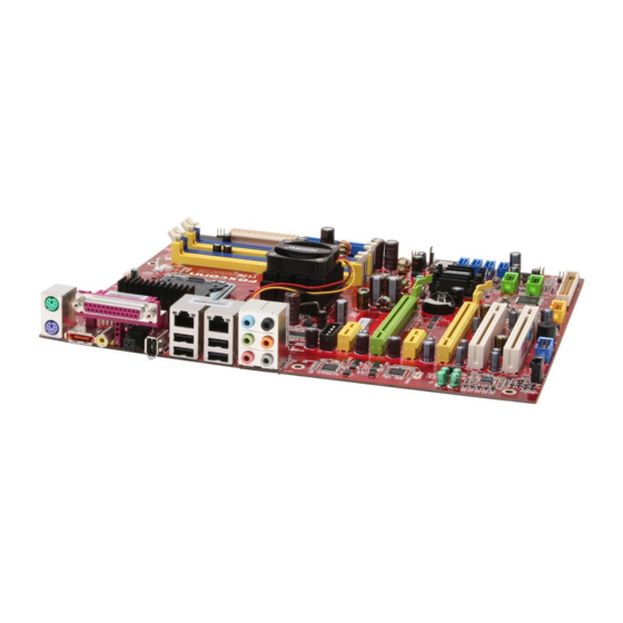
Page 15: Layout
Chapter 1 Product Introduction Layout 16 17 18 16. Chassis Intruder Connector 1. 8-pin ATX_12V Power Connector 17. Front Panel Connector 2. FAN Connector 18. USB Connectors 3. North Bridge: Intel 975X Chipset ® 19. Serial ATA II Connectors (ICH7R Controlled) 4. -
Page 16: Rear Panel Ports
Chapter 1 Product Introduction Rear I/O Ports This motherboard provides the ports as below: 1. PS/2 Mouse Port This port is used to connect a PS/2 mouse. 2. PS/2 Keyboard Port This port is used to connect a PS/2 keyboard. 3. - Page 17 Chapter 1 Product Introduction 8. Line in, Line out, Microphone, Rear, LEF/CEN, Side Jacks Port 2-channel 4-channel 6-channel 8-channel Blue Line In Line In Line In Line In Green Line Out Front Speaker Out Front Speaker Out Front Speaker Out Pink Mic In Mic In...
-
Page 18: Cpu
Chapter 1 Product Introduction Chapter This chapter introduces the hardware installation process, in- cluding the installation of the CPU, memory, power supply, slots, and pin headers, and the mounting of jumpers. Cau- tion should be exercised during the installation of these modules. - Page 19 Chapter 2 Installation Instructions This motherboard supports processor including Core Duo, Pentium ® Extreme Edition, Pentium D, Pentium 4processors in an LGA775 package with a Front ® ® Side Bus (FSB) of 1066/800 MHz. For the detailed CPU support list on this motherboard, please visit the website: http://www.foxconnchannel.com Installation of CPU...
- Page 20 Chapter 2 Installation Instructions 3. Hold CPU with thumb and forefinger. Ensure fingers align to socket cutouts. Match the CPU triangle marker to Pin 1 position as shown below. The alignment key also provides the orientation directed function. Lower the CPU straight down without tilting or sliding the CPU in the socket.
- Page 21 Chapter 2 Installation Instructions 5. Close the load plate, and slightly push down the tongue side. 6. Lower the lever and lock it to the load plate, then the CPU is locked completely. Note : Excessive temperatures will severely damage the CPU and system.
-
Page 22: Memory
Chapter 2 Installation Instructions Memory This motherboard includes four 240-pin slots with 1.8V for DDR2. These slots support dual channel DDR2 memory technology up to 10.7GB/s. You must install at least one memory bank to ensure normal operation. Recommended Memory Configurations The following table list is the recommended memory configurations. - Page 23 Chapter 2 Installation Instructions Warning : Be sure to unplug the AC power supply before adding or removing expansion cards or other system peripherals, especially the memory devices, otherwise your motherboard or the system memory might be seriously damaged. For the detailed memory support list on this motherboard, please visit the website: http://www.foxconnchannel.com...
-
Page 24: Power Supply
Chapter 2 Installation Instructions Power Supply This motherboard uses an ATX power supply. In order to avoid damaging any devices, make sure that they have been installed properly prior to connecting the power supply. 24-pin ATX Power Connector 24-pin ATX power connector: PWR1 RSVD PS-ON PWR1 is the ATX power supply connector. -
Page 25: Other Connectors
Chapter 2 Installation Instructions Note: We strongly recommend that you use 350 W power supply or above. If you use the Dual PCI Express Graphics Cards, we recommend that you use 500W power supply or above. Other Connectors This motherboard includes connectors for FDD devices, IDE devices, Serial ATA devices, USB devices, IR module, and others. - Page 26 Chapter 2 Installation Instructions Front Panel Connector: FP1 PW R SW Empt y PW RL ED This motherboard includes one connector for con- necting the front panel switch and LED indicators. HD-L ED R E S E T HDD LED Connector (HD-LED) The connector connects to the case’s HDD indicator LED indicating the activity status of hard disks.
- Page 27 Chapter 2 Installation Instructions Serial ATA II Connectors: SATA_1, SATA_2, SATA_3, SATA_4 The Serial ATA II connector is used to connect the Serial ATA II device to the motherboard. These connectors support the thin Serial ATA II cables for primary storage devices. The current Serial ATA II interface allows up to 300MB/s data trans- GND GND T X +...
- Page 28 Chapter 2 Installation Instructions USB Headers: F_USB1, F_USB2 Empty Besides four USB ports on the rear panel, the series of motherboards also have two 10-pin headers on board which may connect to front panel USB cable (optional) 5 V_ DUAL 5 V_ DUAL to provide additional four USB ports.
-
Page 29: Expansion Slots
Chapter 2 Installation Instructions Expansion Slots This motherboard includes two 32-bit master PCI bus slots, two PCI Express x 1 slots and two PCI Express x 16 slots. PCI Slots The expansion cards can be installed in the two PCI slots. PCI slots support cards such as a LAN card, USB card, SCSI card and other cards that comply with PCI specifications. -
Page 30: Jumpers
Chapter 2 Installation Instructions Jumpers The users can change the jumper settings on this motherboard if needed. This section explains how to use the various functions of this motherboard by chang- ing the jumper settings. Users should read the following content carefully prior to modifying any jumper settings. -
Page 31: Chapter 3 Bios Description
Chapter 3 BIOS Description Chapter This chapter tells how to change system settings through the BIOS Setup menus. Detailed descriptions of the BIOS param- eters are also provided. You have to run the Setup Program when the following cases occur: 1. - Page 32 Chapter 3 BIOS Description Enter BIOS Setup The BIOS is the communication bridge between hardware and software, correctly setting up the BIOS parameters is critical to maintain optimal system performance. Power on the computer, when the following message briefly appears at the bottom of the screen during the POST (Power On Self Test), press <Del>...
-
Page 33: Advanced Chipset Features
Chapter 3 BIOS Description Advanced BIOS Features The advanced system features can be set up through this menu. Advanced Chipset Features The values for the chipset can be changed through this menu, and the sys- tem performance can be optimized. Integrated Peripherals All onboard peripherals can be set up through this menu. - Page 34 Chapter 3 BIOS Description Standard CMOS Features This sub-menu is used to set up the standard CMOS features, such as the date, time, HDD model and so on. Use the arrow keys select the item to set up, and then use the <PgUp> or <PgDn> keys to choose the setting values. Standard CMOS Features Menu Date This option allows you to set the desired date (usually as the current day) with...
- Page 35 Chapter 3 BIOS Description Award (Phoenix) BIOS can support 3 HDD modes: CHS, LBA and Large or Auto mode. For HDD<528MB For HDD>528MB & supporting LBA (Logical Block Addressing) Large For HDD>528MB but not supporting LBA Auto Recommended mode Floppy Drive A This option allows you to select the kind of FDD to be installed, including “None”, [360K, 5.25 in], [1.2M, 5.25 in], [720K, 3.5 in], [1.44M, 3.5 in] and [2.88 M, 3.5 in].
- Page 36 Chapter 3 BIOS Description FOX Central Control Unit FOX Central Control Unit Menu v[Smart BIOS] Smart Power LED Smart debug LED function within power LED. Enable this function, the power LED status can show the system status of POST process. System Status Power LED Status Normal...
- Page 37 Chapter 3 BIOS Description vFOX Intelligent Stepping User can select different overclocking option by this item. The available set- ting values are: Manual, Auto, Power gaming, Data Mining, Office, Energy Saving. vC1E Function(optional) This option is used to enabled or disabled the C1E(Enhanced Halt State) function.
- Page 38 Chapter 3 BIOS Description DRAM Configuration Menu vDRAM Timing Selectable This item determines DRAM clock/ timing using SPD or manual configuration. The available setting values are: By SPD and Manual. vCAS Latency Time This item determines CAS Latency. The available setting values are: 3, 4, 5, 6 and Auto.
- Page 39 Chapter 3 BIOS Description Advanced BIOS Features Advanced BIOS Features Menu vCPU Feature Press enter to set the items of CPU feature. vHard Disk Boot Priority This option is used to select the priority for HDD startup. After pressing <Enter>, you can select the HDD using the <PageUp>/<PageDn> or Up/ Down arrow keys, and change the HDD priority using <+>...
- Page 40 Chapter 3 BIOS Description vBoot Up NumLock Status This item defines if the keyboard Num Lock key is active when your system is started. The available setting values are: On and Off. vSecurity Option W hen it is set to “Setup”, a password is required to enter the CMOS Setup screen;...
- Page 41 Chapter 3 BIOS Description CPU Feature Menu Delay Prior to Thermal This option is used to set the delay time before the CPU enters auto thermal mode. The setting values are: 4 Min, 8 Min, 16 Min, 32 Min. vLimit CPUID MaxVal The option is used to set limit CPUID MaxVal.
- Page 42 Chapter 3 BIOS Description Advanced Chipset Features Advanced Chipset Features Menu vCurrent PCIE Graphic Link Width This option is used to show PCIE graphic link width. vSLP_S4# Assertion Width This option is used to set SLP_S4# assertion width. vPCI Express Root Port Func Press <Enter>...
- Page 43 Chapter 3 BIOS Description Integrated Peripherals Integrated Peripherals Menu vOnChip IDE Device Press enter to set onchip IDE device. vOnboard Device Press enter to set onboard device. vSuperIO Device Press enter to set onboard SuperIO device.
- Page 44 Chapter 3 BIOS Description OnChip IDE Device Menu vDelay For HDD (Secs) You can select a delay from 1 to 15 seconds in the cold boot process. vIDE HDD Block Mode This option is used to set whether the IDE HDD block mode is allowed. vIDE DMA transfer access This option is used to set the IDE transfer access—with it set to Enabled, the IDE Transfer Access uses the DMA mode;...
- Page 45 Chapter 3 BIOS Description Onboard Device Menu vJMicron JMB361 Controller This option is used to enable or disable JMicron JMB361Controller vUSB Controller This option is used to set whether the USB Controller is enabled. The available setting values are: Disabled and Enabled. vUSB 2.0 Controller This option is used to set whether the USB 2.0 Controller is enabled.
- Page 46 Chapter 3 BIOS Description SuperIO Device Menu vOnboard FDC Controller This option is used to set whether the Onboard FDC Controller is enabled. The available setting values are: Disabled and Enabled. vOnboard Serial Port1/2 This option is used to assign the I/O address and interrupt request (IRQ) for the onboard serial port 1/2.
- Page 47 Chapter 3 BIOS Description Power Management Setup Power Management Setup Menu vACPI function ACPI stands for “Advanced Configuration and Power Interface”. ACPI is a standard that defines power and configuration management interfaces be- tween an operating system and the BIOS. In other words, it is a standard that describes how computer components work together to manage system hardware.
- Page 48 Chapter 3 BIOS Description vCase Open Warning This option is used to enable or disable case open warning function. vWake up by PCI card This item is used to set the system to wake up by PCI card. vPower On by Ring If this item is enabled, it allows the system to resume from a software power down or power saving mode whenever there is an incoming call to an installed fax.
- Page 49 Chapter 3 BIOS Description vPOWER ON Function This option is used to set the power on method for your PC. Setting values include: Any KEY, Mouse Click, Both, BUTTON ONLY. vPWRON After PWR-Fail This item is used to set what action the PC will take with the power supply when it resumes after a sudden power failure.
- Page 50 Chapter 3 BIOS Description PnP/PCI Configurations PnP/PCI Configurations Menu Init Display First This option is used to set which display device will be used first when your PC starts up. Reset Configuration Data This option is used to set whether the system is permitted to automatically distribute IRQ DMA and I/O addresses when each time that the machine is turned on.
- Page 51 Chapter 3 BIOS Description PC Health Status PC Health Status Menu vVCC 3.3/Vcore/1.8V/1.5V/+5V/+12V/VSB3.3/Voltage Battery The current voltages will be automatically detected by the system. vCurrent CPU/System Temperature The current system/CPU temperature will be automatically detected by the system. vCPU/SYSTEM/FAN1 Speed The system/CPU fan speed will be automatically detected by the system.
- Page 52 Chapter 3 BIOS Description Load Fail-Safe Defaults Press <Enter> to select this option. A dialogue box will pop up that allows you to load the default BIOS settings. Select <Y> and then press <Enter> to load the defaults. Select <N> and press <Enter> to exit without loading. The defaults set by BIOS set the basic system functions in order to ensure system stability.
- Page 53 Chapter 3 BIOS Description If you do not want to set a password, just press <Enter> when prompted to enter a password, and in the screen the following message will appear. If no password is keyed in, any user can enter the system and view/modify the CMOS settings. Password Disabled!!! Press any key to continue …...
-
Page 54: Chapter 4 Driver Cd Introduction
Chapter 4 Driver CD Introduction Chapter The utility CD that came with the motherboard contains use- ful software and several utility drivers that enhance the motherboard features. This chapter includes the following information: Utility CD content Installing drivers Installing Utilities... - Page 55 Using this choice, you can install all the additional software for your motherboard. A. FOX ONE B. Fox LiveUpdate C. Microsoft DirectX9.0 D. Adobe Acrobat Reader E. Norton Security F. Creat RAID Driver Floppy 3. Click on dynamic FOXCONN logo to visit our homepage.
-
Page 56: Installing Drivers
Chapter 4 Driver CD Introduction Installing Drivers There are two ways to install drivers, manual or automatic. Click the drivers that you want to install and begin the setup steps by manual. Or you just click “One Click Setup” button to install the drivers by automatic after install Intel Chipset Driver. - Page 57 Chapter 4 Driver CD Introduction Chapter This chapter will introduce how to use attached software. This chapter provides the following information: FOX ONE Fox LiveUpdate...
-
Page 58: Directions For Bundled Software
Chapter 5 Directions for Bundled Software FOX ONE FOX ONE is a powerful utility for easily modifying system settings. It also allows users to monitor various temperature values, voltage values, frequency and fan speed at any time. With FOX ONE, you can -Modify system performance settings, such as bus speeds, CPU voltages, fan speed, and other system performance options that are supported by the BIOS... - Page 59 Click this button to configurate the parameters for the program. It determines which items will be shown in shorten mode. Homepage Click this button to visit Foxconn motherboard website. 2. CPU Page - CPU Control This page lets you select and run the FOX ONE developed benchmarks to determine the current performance level of the system.
- Page 60 Chapter 5 Directions for Bundled Software Go to CPU page Close this page Ajust by manual Reset the Apply the changes changes Select the different benchmarks 3. Freq. Page - Frequency Control This page lets you set memory and PCI Express frequency by manual. Go to Freq.
- Page 61 Chapter 5 Directions for Bundled Software 4.1 Limit Setting - CPU Temp. This page lets you to set CPU high limit temperature and enable the alert function. Show current CPU Go to Adjust page temperature value Enable alert function when the CPU temperature is higher than high limit value Show current high...
- Page 62 Chapter 5 Directions for Bundled Software 4.3 Limit Setting - CPU Fan This page lets you to set CPU fan low limit rpm and enable the alert function. Show current CPU fan rpm value Enable alert function when the CPU fan rev is lower than low limit rpm value Show current low limit...
- Page 63 Chapter 5 Directions for Bundled Software 4.5 Limit Setting - Chassis Fan This page lets you to set chassis fan low limit rpm and enable the alert function. Show current Chassis fan rpm value Enable alert function when the chassis fan is lower than low limit rpm value Show current low limit rpm value of chassis fan...
- Page 64 Chapter 5 Directions for Bundled Software 6. Fan Page - Fan Control This page lets you enable smart Fan function or set fan speed by manual. Go to Fan page Enable or disable smart fan function Set fan speed by dragging the lever Reset the changes Apply the changes...
-
Page 65: Fox Liveupdate
Chapter 5 Directions for Bundled Software Fox LiveUpdate Fox LiveUpdate is a useful utility for backuping and updating the system BIOS, drivers and utilities by local or online. Supported Operating Systems: -W indows 2000 -Windows XP (32-bit and 64-bit) Windows 2003 (32-bit and 64-bit) Using Fox LiveUpdate: 1.1 Local Update - BIOS Info. - Page 66 Chapter 5 Directions for Bundled Software 1.2 Local Update - Backup This page lets you backup your system BIOS. Click “Backup”, then give a name. Click “Save” to finish the backup operation. Key in a BIOS name Click here 1.3 Local Update - Update This page lets you update your system BIOS from Internet.
- Page 67 Chapter 5 Directions for Bundled Software 2.1 Online Update - Update BIOS This page lets you update your system BIOS from Internet. Click “start”, it will search the new BIOS from Internet. Then follow the wizard to finish the update operation.
- Page 68 Chapter 5 Directions for Bundled Software 2.2 Online Update - Update Driver This page lets you update your system drivers from Internet. Click “start”, it will search the new drivers from Internet. Then follow the wizard to finish the update operation.
- Page 69 Chapter 5 Directions for Bundled Software 2.3 Online Update - Update Utility This page lets you update utilities from Internet. Click “start”, it will search the new utilities from Internet. Then follow the wizard to finish the update operation. Click here Current information Search new utilities from Internet...
- Page 70 Chapter 5 Directions for Bundled Software 3.1 Configure - option This page lets you set auto search options. After your setting, the utility will start searching and related information will show on the task bar. Click here Set auto search options Select search which kind of versions...
- Page 71 Chapter 5 Directions for Bundled Software 3.2 Configure - System This page lets you set the backup BIOS location and change different skin of the utility. Click here Set the location of download files or auto backup BIOS Select different skin of the software Reset to default value Determine if the Fox LiveUpdate...
-
Page 72: Appendix
Catalyst Control Center: - A CrossFire Ready motherboard such as Foxconn’s 975X7ABseries - A CrossFire Edition graphics card that works as the master graphics card - A CrossFire... - Page 73 Appendix CrossFire Edition CrossFire Ready graphics card graphics card Step 3. Connect 1 of the Power Extension Cable to the graphics card power connector, and connect 2 to the power supply connector. Power Extension Cable Step 4. Correctly connect the DMS-59 cable to the DVI monitor connector and two graphics cards that you install as shown.
- Page 74 Appendix Step 5. Power on your computer and boot into OS (Windows XP with SP2 or W indows XP Professional x64 Edition). Step 6. Please uninstall any existing video drivers that could possibly create a conflict before attempting to install this display card. Step 7.
-
Page 75: Audio Configuration
Appendix Audio Configuration The ALC882 provide 10 channels of DAC that simultaneously support 7.1 sound playback, plus 2 channels of independent stereo sound output (multiple streaming) through the Front-Out-Left and Front-Out-Right channels. Flexible mixing, mute, and fine gain control functions provide a complete integrated audio solution for next generation multimedia PCs. - Page 76 Appendix 4. Sound Effect Introduction Allows you to set your listening environment, adjust the equalizer, set the Karaoke, or select pre-programmed equalizer settings. 1. Click here 2. Select environment 3. Set equalizer 4. Click OK 5. Mixer Introduction Allows you to set audio output and audio input volume. 1.
- Page 77 Appendix 6. Bass Management setting Introduction Allows you to manage your bass settings. 1. Click here 2. Adjust your desired settings 3. Test your settings 4. Click OK 7. Audio I/O Introduction Allows you to configure your input/output settings. 1. Click here 2.
- Page 78 Appendix 8. Microphone Introduction Allows you to configure your input/output settings and to check if your audio devices are connected properly. 1. Click here 2. Click here 3. Click OK...
Need help?
Do you have a question about the 975X7AB and is the answer not in the manual?
Questions and answers