Table of Contents
Advertisement
Quick Links
Advertisement
Table of Contents

Subscribe to Our Youtube Channel
Related Manuals for Wisenet XNV-6123R


Summary of Contents for Wisenet XNV-6123R
- Page 1 NETWORK CAMERA User Manual XNV-6123R XNO-6123R...
- Page 2 Network Camera User Manual Copyright ©2021 Co., Ltd. All rights reserved. Hanwha Techwin Trademark Each of trademarks herein is registered. The name of this product and other trademarks mentioned in this manual are the registered trademark of their respective company. Restriction Copyright of this document is reserved.
- Page 3 overview IMPORTANT SAFETY INSTRUCTIONS 22. Although a rapid change in temperature could cause frost inside the dome, there will be no problem with the video. 1. Read these instructions. 23. This device has been verified using STP cable. The use of appropriate GND grounding and STP cable 2.
- Page 4 For below models only. for monitoring purposes. XNV-6123R / XNO-6123R When a new product box is opened (or during the initial use of the product), moisture might build up on the glass of the camera. The built-up moisture disappears naturally within a few hours after powered on.
-
Page 5: Table Of Contents
CONTENTS OVERVIEW Important Safety Instructions NETWORK CONNECTION AND Connecting the Camera Directly to Local Recommended PC Specifications Area Networking SETUP Recommended Micro SD/SDHC/SDXC Connecting the Camera Directly to a DHCP Memory Card Specifications Based DSL/Cable Modem NAS recommended specs Using Device Manager Video output Automatically searching camera Optional Accessories for Installation... -
Page 6: Recommended Pc Specifications
overview RECOMMENDED PC SPECIFICATIONS NAS RECOMMENDED SPECS ~ CPU : Intel(R) Core(TM) i7 3.4 GHz or higher ~ Recommended capacity : 200GB or higher is recommended. ~ RAM : 8G or higher ~ For this camera, you are recommended to use a NAS with the following manufacturer’s specs. ~ Recommended browser: Chrome Recommended products : QNAP NAS, Synology NAS ~ Supported browsers: Chrome, Safari, Firefox, MS Edge(chromium based) - Page 7 Vandal Dome Camera Bullet Camera XNV-6123R XNO-6123R English _7...
-
Page 8: Optional Accessories For Installation
Backbox Pole Mount SBP-300LMW (Parapet Mount) SBP-156LMW (Parapet Mount) SBP-300CMW (Ceiling Mount) SBP-156CMW (Ceiling Mount) SBP-300WMW (Wall Mount) SBP-300WMW1 (Wall Mount) XNV-6123R SBP-187HMW SBV-180WW SBP-300NBW (Instalation Box) SBP-300NBW (Wall Mount Base) SBP-300PMW (Pole Mount) SBP-300PMW1 (Pole Mount) SBP-300KMW (Corner Mount) -
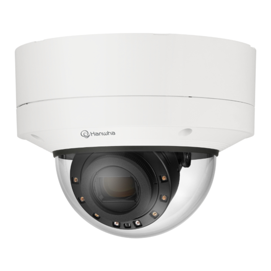
Page 9: Vandal Dome Camera
WHAT’S INCLUDED AT A GLANCE As for each sales country, accessories are not the same. Pipe-cover Mount-plate Camera-case Camera-module Dome-cover <XNV-6123R> Lens Illumination Sensor Reset button Zoom/Focus IR LED Control Button Network Port Use installation screws of at least M4, L30 for the installation of this product. -
Page 10: Installation
vandal dome camera INSTALLATION 2. Take off the lens cover protecting the camera lens. This camera is waterproof and in compliance with the IP67 / IP6K9K spec, but the jack connected to the external cable is not. You are recommended to install this product below the edge of eaves to prevent the cable from being externally exposed. Precautions before installation Ensure you read out the following instructions before installing the camera: ~ Select an installation site that can hold at least 5 times the camera’s weight. - Page 11 Removing a Micro SD card Installation (mount plate) Gently press down on the exposed end of the Micro SD card as shown in the diagram to eject the Micro SD [Directly installing on wall/ceiling] card from the slot. 1-1. Attach the installation template on the desired surface and drill holes for screws and cables. Before removing the Micro SD card, in <Setup ( )>-<Event>-<Storage>, set the device to <Off>...
- Page 12 vandal dome camera [Installing using pipe] 2-3. Place the pipe on the mount plate. 2-4. Fix the mount plate using appropriate screws. 2-1. Attach the installation template and drill holes for screws and cables. 2-5. Pull out necessary cables among network/power/audio/alarm cables through the pipe. 2-2.
- Page 13 1-4. Mount the cable bushing to the camera case. 2-3. Mount the cable bushing to the camera case. [Installing the network cable] (IP66) [Installing audio/alarm cables] 2-1. Pull off the extruded part of the 1-hole cable bushing provided. 2-2. Use the cap installer to pass through the RJ45 cable. 3-1.
- Page 14 vandal dome camera 4. Join the mount plate with the camera case. Installing the camera module 1. Connect the network/power/audio/alarm cables to the camera module terminal. 2. Attach the camera module to the case. A magnet is embedded at the bottom of the module Take caution not to allow any foreign objects between the attaching surfaces.
- Page 15 Assembling the dome cover [Using Weather cap] 1. Remove the screws from the dome cover. [Directly installing on wall/ceiling] 1. Assemble the dome cover. Make sure to firmly tighten the fastening screws so that there is no water damage issue. TR20 TR20 2.
- Page 16 vandal dome camera Outside installation When you install it outside of the building, please waterproof it with waterproof butyl rubber tape (can be purchased in stores) so that water does not leak from the gap of the cable connected to the outside. 1.
-
Page 17: Bullet Camera
bullet camera WHAT’S INCLUDED AT A GLANCE As for each sales country, accessories are not the same. Mount plate Sunshield fixing screw Bottom cover Tooth washer Sunshield <XNO-6123R> Pipe-cover Camera body Reset button Power Port Test monitor out port Audio/Alarm cable (DC12V) port Micro USB port... -
Page 18: Installation
bullet camera INSTALLATION Removing a Micro SD card Gently press down on the exposed end of the Micro SD card as shown in the diagram to eject the Micro SD card from the slot. This camera is waterproof and in compliance with the IP67 spec, but the jack connected to the external cable is not. You are recommended to install this product below the edge of eaves to prevent the cable from being externally exposed. - Page 19 Installation (Mount plate) [Installing using pipe] 2-1. Attach the installation template and drill holes for screws and cables. [Directly installing on wall/ceiling] 1-1. Attach the installation template on the desired surface and drill holes for screws and cables. 2-2. Separate the pipe cover of the Mount plate by pressing its sides. 1-2.
- Page 20 bullet camera 2-3. Place the pipe on the Mount plate. 1-4. Mount the cable bushing to the Bottom cover. 2-4. Fix the Mount plate using appropriate screws. 2-5. Pull out necessary cables among network/power/audio/alarm cables through the pipe. Installation (Bottom cover) Use a cable bushing compliant with the network cable to be connected.
- Page 21 2-3. Mount the cable bushing to the Bottom cover. 4. Join the Mount plate with the Bottom cover. TR20 [Installing audio/alarm cables] 3-1. Mount the cable bushing of the provided audio/alarm cables to the Bottom cover. English _21...
- Page 22 bullet camera Installing the camera module 3. Join the camera body with the Bottom cover. 1. Hang the safety wire on the hook inside the bottom cover. Make sure to firmly tighten the fastening screws so that there is no water damage issue. TR20 e.g.
- Page 23 5. Use the sunshield mounting screws and tooth washers to join the sunshield to the camera body. Outside installation Once installation is complete, peel off the protective cover from the camera lens. When you install it outside of the building, please waterproof it with waterproof butyl rubber tape (can be purchased in stores) so that water does not leak from the gap of the cable connected to the outside.
-
Page 24: Installation & Connection
installation & connection ADJUSTING THE MONITORING DIRECTION FOR THE CAMERA Adjust the direction of IR LEDs not to hinder their view by an instrument. Tilt Lens rotation ` Adjusting the monitoring direction You can adjust the camera direction only when the camera is fixed on the ceiling. At this time, rotating the main body of the camera in the left and right direction is called PAN, and adjusting Adjust the direction of IR LEDs not to hinder their view by a weather cap (if any). -
Page 25: Connecting With Other Device
Power Monitor for installation Power <XNV-6123R> <XNO-6123R> The Test Monitor Out port of the product is provided for easier installation, and is not recommended for monitoring purposes. The Micro USB port of the product is provided for easier installation, and is not recommended for monitoring purposes. - Page 26 If you want to connect an external device, you must turn off the external device before proceeding. 1. Install the Wisenet Installation application. Connect the set and the adapter power line first, and then connect the power cable to the outlet on the wall.
- Page 27 Connecting to Audio Input/Output ~ Audio Codec - Audio In : G.711 PCM (Bit Rate: 64kbps / Sampling Frequency: 8kHz), G.726 ADPCM (Bit Rate: 16Kbps, 24Kbps, 32Kbps, 40Kbps / Sampling Frequency: 8kHz), AAC (Bit Rate: 48Kbps / Sampling Frequency: 16kHz) Speaker - Audio Out : G.711 PCM (Bit Rate: 64kbps / Sampling Frequency: 8kHz) ~ Full duplex Audio...
- Page 28 installation & connection Connecting to the I/O port box If devices (e.g., flashing light and siren) that exceed the voltage and current specifications are connected by using the open Connect the Alarm I/O cable to the corresponding port of the port box. collector method, it may cause malfunction.
- Page 29 To connect the alarm out If devices (e.g., flashing light and siren) that exceed the voltage and current specifications are connected by using the open collector method, it may cause malfunction. Refer to the alarm out connection diagram below when connecting devices that exceed the voltage and current specifications.
-
Page 30: Connecting The Camera Directly To Local Area Networking
network connection and setup network connection and setup You can set up the network settings according to your network configurations. CONNECTING THE CAMERA DIRECTLY TO A DHCP BASED DSL/CABLE MODEM CONNECTING THE CAMERA DIRECTLY TO LOCAL AREA NETWORKING Connecting to the camera from a local PC in the LAN 1. -
Page 31: Using Device Manager
USING DEVICE MANAGER If using a Broadband Router ~ IP Address : Enter an address falling in the IP range provided by the Broadband Router. Device manager program can be downloaded from <Technical Support>-<Online Tool> menu at Hanwha Techwin website ex) 192.168.1.2~254, 192.168.0.2~254, (http://www.hanwha-security.com). -
Page 32: Manually Registering Camera
network connection and setup Configuring Dynamic IP AUTOMATICALLY CONFIGURING IP Receive IP address from DHCP 1. Click the camera from the list that you want to automatically ~ Example of the Dynamic IP environment configure the IP. XNO-6123R - If a Broadband Router, with cameras connected, is assigned an IP address by the DHCP server 2. -
Page 33: Port Range Forward (Port Mapping) Setup
Port forwarding can be done without additional router setup if the router supports the UPnP (Universal Plug and Play) function. For more information, refer to the user manual of the applicable router. After connecting the network camera, select the checkbox from the menu <Quick connect> in <Wisenet DDNS> in “Settings -> Network -> DDNS”. -
Page 34: Connecting To The Camera From A Shared Local Pc
2. From the remote PC, launch the Internet browser and type the DDNS URL address of the camera, or the IP address of the Broadband Router in the address bar. ex) http://ddns.hanwha-security.com/ID To use Wisenet DDNS, sign up at the Wisenet DDNS homepage (http://ddns.hanwha-security.com) and register the product at [My DDNS]>[Register Product]. 34_ network connection and setup... -
Page 35: Connecting To The Camera
To register your device to the <DDNS> server, visit http://ddns.hanwha-security.com and register your device 1. Launch the Internet browser. first, and then set the Web Viewer’s <Network> - <DDNS> to <Wisenet DDNS>, as well as providing <Product ID> that had been used for DDNS registration. -
Page 36: Password Setting
web viewer PASSWORD SETTING CAMERA WEB VIEWER SETUP When you access the product for the first time, you must register the 1. Click the [Setup ( )] icon. login password. 2. The Settings window appears. 3. You can configure settings for the camera’s basic information, video, audio, network, event, analysis, and system over the network. -
Page 37: Troubleshooting
appendix TROUBLESHOOTING PROBLEM SOLUTION PROBLEM SOLUTION Voice is not recorded even though When an Windows 10 user accesses ~ You must enable the <Audio In> check box in <Basic> - <Video Profile>. ~ This is what happens when microphone driver has been set to Realtek driver. audio input settings are configured. - Page 38 Any changes or modifications in construction of this device which are not expressly approved by the party responsible for compliance could void the user's authority to operate the equipment. This device complies with part 15 of the FCC Rules. Operation is subject to the following two conditions: (1) This device may not cause harmful interference, and (2) this device must accept any interference received, including interference that may cause undesired operation.
Need help?
Do you have a question about the XNV-6123R and is the answer not in the manual?
Questions and answers