Table of Contents
Advertisement
Quick Links
Advertisement
Table of Contents

Related Manuals for Sricam SP006


Summary of Contents for Sricam SP006
- Page 1 IP Camera For PC View) SP006 User Manual...
- Page 2 Thank you for buying our products This security camera can offer you the freedom to get your home or business surveillance via network anytime and anywhere, and you do not need any special driver software, just by Safari, Firefox, Google Browser the Microsoft IE, , your iPhone or other cell phone with Android system.
-
Page 3: Table Of Contents
Table of CONTENTS 1. Product Introduction ...................3 1.1. System Requirements..................3 1.2. Product Views……………..........…………....3 1.2.1 Front View......................3 1.2.2 Interface View....................4 1.3. Hardware Installation..................4 1.4. Software Installation..................5 2. Software Operation....................5 2.1. P2P ID Finder Software..................5 2.1.1. Search The IP address of the Camera.............6 2.1.2. -
Page 4: Product Introduction
1. Product Introduction 1.1. System Requirements... -
Page 5: Hardware Installation
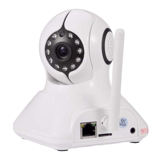
1.3 Hardware Installation Follow the steps below to set up your camera hardware. Make sure to follow each step carefully to ensure that the camera operates properly 1. Install the Wi-Fi antenna (For wireless IP Camera) . 2. Plug the power adaptor into camera 3. -
Page 6: Software Operation
2. Open the “P2P ID Finder” file, Click , Install the IPCam ActiveX(This software is for P2P ID Finder Preview the camera). 3. P2P ID Finder: click ,The P2P ID Finder.exe will run automatically. ( No need install. You can copy this software to your desktop.) Figure 1.3 2. -
Page 7: Preview The Camera
1. No IP Cameras found within LAN. After about 1 minute search, the Equipments List Field not show the IP address. 2. IP Cameras have been installed within LAN. All the IP Cameras will be listed and the total number is displayed in the Equipments list field as shown in Figure 2.1 Note:... -
Page 8: Real-Time Video Demonstration
3: Real-time Video Demonstration. 3.1. Camera Login: You can access the camera through IP Camera Tool or IE, Firefox, Safari, Google Chrome or other standard browser directly. 1. Double click the IP address of the IP Camera listed (Figure 2.1). The default browser you use will run automatically and come to the camera login interface. -
Page 9: View Via Ie Browser
Figure 3.1 Default username: admin Password: NO PASSWORD. Input the correct user name and password, the Sign In interface will pop-up. There are three modes to login (figure 3.2). Figure 3.2 (1) ActiveX Mode (For IE Browser): available in IE6.0 or above explorer (2) “Server Push Mode”: available in Firefox, Safari, and Google browser. - Page 10 The first time you login the camera, you will get ActiveX prompt as the picture below, please download the Ocx(or run in CD) to install, then choose Run Add-on, refresh and login the camera again, then you will see live video, details as below: Figure 3.3 After Downloading Ocx-Setup (oPlayer Software), Click and install it.
- Page 11 Figure 3.3 Windows XP system Figure 3.4 Win7 System Note: If there is still no live video after run ActiveX, please try to enable the ActiveX options of IE security settings, please do the follow steps: 1. Close the firewall of your computer. 2.
- Page 12 Figure 3.6 In Addition: you can also click “start” menu->“Internet Explorer”, choose “Internet attributes “ to enter, or via “Control Panel” ->“Internet Explorer”, enter to Security setting. 3. If there is still no image, please close your anti-virus software, and then try step 1 & 2 again.
-
Page 13: View Via Safari, Firefox, Google Browser
NOTE: Make sure that the firewall or anti-virus software doesn’t block the software or ActiveX. If you couldn’t see live video, please close your firewall or anti-virus software, and try again. 3.3. View via Safari, Firefox, Google Browser Choose Server Push Mode (For Safari, Firefox, Google Browser), and sign in Server Push Mode doesn’t support ActiveX, so some functions are not available, such As Record, Audio, Talk, Speaker, Zoom... - Page 14 Figure 3.8 This button enables alarm detections. When alarm the color turn to red. This button make the camera Vertical cruise (for the Pan/Tilt Cams). This button make the camera Level cruise (for the Pan/Tilt Cams). Turn on/off IR leds This button flips the image vertically.
-
Page 15: Administrator Settings Instruction
This button opens the IP camera’s Backend Menu. This option opens the camera’s recording functionality menu. This option takes a snapshot of the current screen and saves the snapshot to the PC’s Hard Disk. This option enables Camera-to-User audio. If the online user has speakers connected and configured to their PC, clicking this option will allow them to hear audio from the location of the camera. -
Page 16: Ptz Settings
name, host address, Http port will automatically be filled, require the user to fill in the correct account name and password, click “Add.” Repeat this process you can continue to add devices. Finally do not forget to click on the “Settings” button. Figure 3.9 Figure 3.10 3.5.2 PTZ Settings... -
Page 17: Basic Network Settings
Figure 3.11 3.5.3 Basic Network Settings ure 3.12 This sector is for DHCP and IP configuration, port forwarding is needed, If you choose to set IP address,please fill in the relative IP address, subnet mask, gateway, DNS server, Http port; 3.5.4 Wireless Settings 1. -
Page 18: Dynamic Dns Settings
Figure 3.13 3.5.5 Dynamic DNS Settings (DDNS) 3.5.5.1 DDNS Setting: (1): Click > “DDNS Service Settings”. Figure 3.14 (2): Choose the DDNS, there are 3 kinds of options: (1): The camera which you have bought is P2P IP Camera, Normally you didn’t need use DDNS setting part. -
Page 19: Port Forwarding Settings
(2): The Third Party DDNS: This domain is provided by the 3rd party, such as DynDns. Oray, 3322 If you use the third party DDNS, please choose the server you need, such as“3322.org” or“ dyndns.org” as below: Figure 3.16 You have to register an account firstly, keep the user, password, host, then fill in it. Note: Only one DDNS can be chosen. - Page 20 Figure 3.17 Make sure the “Subnet Mask”, “Gateway”, “DNS Server” is the same as your router. 2: Setting Port Forwarding in the router. This is the most important step. Set port forwarding in router refer to the IP of your camera correctly, then the DDNS will work.
- Page 21 Figure 3.18 DLINK: (1) Login the router. (2) Choose “Advanced”, select “Virtual Servers” (3) Input the port, IP address, Protocol, then click save. Note: The “public port” & “private port” should be the same as camera’s port, choose the protocol to be “both”.
-
Page 22: Ddns Register
Figure 3.19 After all these 4 steps done, then you can use the DDNS freely, check the DDNS status from the camera as below, and get the link of DDNS for internet view. Step: “Login”>” ”>”Device Info”: Figure 3.20 3.5.5.3 DDNS Register For example, you can go to Dyndns website to register a free account. - Page 23 Step1: enter http://www.dyndns.com/ and Create Account Figure 3.21 Step2: Set the username and password as below: Figure 3.22 Step3: After a minute, you will receive a E-mail from DynDNS Support and it will give you a confirmation address (e.g. https://www.dyndns.com/confirm/create/ONMzltcCBk6mcHJI5MhVD0g)
- Page 24 Figure 3.23 Figure 3.24 Step4: When the Account Confirmed, login and start using your account. Choose Add Host Services(Figure 3.25) and enter Add New Hostname (Figure 3.26)page. Figure 3.25...
- Page 25 Figure 3.26 Step5: On the Add New Hostname page. 1) input your Hostname. 2) choose Host with IP address 3) click Use auto detected IP address xxx.xx.xx.xxx. Then click Create Host. 4) after you have added a New Hostname , you need “Proceed to checkout” Figure 3.27...
- Page 26 Figure 3.28 Figure 3.29 Step6: Now you obtained a Dynamic Domain Name(Figure3.30),and can use it in the DDNS Service Settings(details: 3.5.5) Notice: If you have a dynamic IP address, Make sure you have download the DynDNS’s “Update Client”. And installed it succeed in your computer. Figure 3.30...
-
Page 27: Email And Ftp Service Settings
3.5.6 E-mail and FTP service Settings Figure 3.31 The above setting is a preparation for the alarm function, the sender should be entered the sender’s email address,recipient 1、2、3、4 is filled with recipient E-mail address;SMTP server should be filled with the sender email SMTP server,e.g. the sender email address is abc@163.com,and enter mail.163.com. -
Page 28: Alarm Service Settings
3.5.7. Alarm Service Settings As shown below, there are two modes of alarm trigger, first one is motion detection, please refer to below interface,the sensitivity of motion detection can be adjusted according to the users′ requirement, the higher the number is, the lower sensitivity is;... -
Page 29: Record Schedule
3.5.9 Record Schedule This sector is for SD card recording settings. When the SD card has been inserted, it will show the capacity of the card. At first, you need to format it. It include: Record coverage ,Record time, Timer recording. The settings are like following: Figure 3.35 You can playback the video online. -
Page 30: Back
Figure 3.37 3.5.11 Back After all the settings, click here to go back to camera interface. Figure 3.38... -
Page 31: Warranty
4 Warranty Under normal use condition, products resulting from its own failures in the warranty period will be free maintenance. Warranty Terms as following: 1) Charge-free maintenance of the product is one year. We can repair it for free during the guarantee period (Damages not caused by misuse or vandalism). Repair over guarantee period, we will charge maintenance fee. - Page 32 FCC Information and Copyright This equipment has been tested and found to comply with the limits for a Class B digital device, pursuant to part 15 of the FCC Rules. These limits are designed to provide reasonable protection against harmful interference in a residential installation.
Need help?
Do you have a question about the SP006 and is the answer not in the manual?
Questions and answers