Table of Contents
Advertisement
Quick Links
Operator's Manual
IDEALARC
Register your machine:
www.lincolnelectric.com/register
Authorized Service and Distributor Locator:
www.lincolnelectric.com/locator
Save for future reference
Date Purchased
Code:
(ex: 10859)
Serial:
(ex: U1060512345)
IM480-C
| Issue D ate 11-Aug
© Lincoln Global, Inc. All Rights Reserved.
CV400
®
For use with machines having Code Numbers:
10084, 10085, 10086, 10087, 11087,
11088, 11089, 11354, 11355, 11835,
11836
Advertisement
Table of Contents

Related Manuals for Lincoln Electric 10084


Summary of Contents for Lincoln Electric 10084
- Page 1 Operator’s Manual IDEALARC CV400 ® For use with machines having Code Numbers: 10084, 10085, 10086, 10087, 11087, 11088, 11089, 11354, 11355, 11835, 11836 Register your machine: www.lincolnelectric.com/register Authorized Service and Distributor Locator: www.lincolnelectric.com/locator Save for future reference Date Purchased Code:...
-
Page 2: Safety Precautions
351040, Miami, Florida 33135 or CSA Standard W117.2-1974. A Free copy of “Arc Welding Safety” booklet E205 is available from the Lincoln Electric Company, 22801 St. Clair Avenue, Cleveland, Ohio 44117-1199. BE SURE THAT ALL INSTALLATION, OPERATION, MAINTENANCE AND REPAIR PROCEDURES ARE PERFORMED ONLY BY QUALIFIED INDIVIDUALS. - Page 3 SAFETY ARC RAYS can burn. ELECTRIC SHOCK can 4.a. Use a shield with the proper filter and cover kill. plates to protect your eyes from sparks and 3.a. The electrode and work (or ground) circuits the rays of the arc when welding or observing are electrically “hot”...
- Page 4 SAFETY WELDING and CUTTING CYLINDER may explode SPARKS can if damaged. cause fire or explosion. 7.a. Use only compressed gas cylinders 6.a. Remove fire hazards from the welding area. containing the correct shielding gas for the If this is not possible, cover them to prevent process used and properly operating the welding sparks from starting a fire.
- Page 5 SAFETY PRÉCAUTIONS DE SÛRETÉ 6. Eloigner les matériaux inflammables ou les recouvrir afin de prévenir tout risque dʼincendie dû aux étincelles. Pour votre propre protection lire et observer toutes les instructions et les précautions de sûreté specifiques qui parraissent dans ce 7.
- Page 6 Electric for advice or information about their use of our products. We respond to our customers based on the best information in our posses- sion at that time. Lincoln Electric is not in a position to warrant or guarantee such advice, and assumes no liability, with respect to such infor- mation or advice.
-
Page 7: Table Of Contents
TABLE OF CONTENTS Page Safety Precautions ......................2-5 Introductory Information .......................7 Meaning of Graphic Symbols ....................8-11 General Machine Description....................12 Recommended Processes & Equipment ................12 Design Summary......................12-14 Operational Features & Controls ................12-14 Technical Specifications .....................15 Installation ........................16-18 Safety Precautions .......................16 Location ........................16 Stacking........................16 Input Wiring ........................16 Output Connections......................17... -
Page 8: Meaning Of Graphic Symbols
MEANINGS OF GRAPHIC SYMBOLS The CV-400 nameplate has been designed to use international symbols in describing the function of the various components. Below are the symbols used. POWER ON-OFF SWITCH Input (Power) OUTPUT CONTROL DIAL Output Voltage (Control) Increase/Decrease of Output (Voltage) OUTPUT CONTROL “LOCAL-REMOTE”... - Page 9 CIRCUIT BREAKER Circuit Breaker THERMAL PROTECTION LIGHT High Temperature VOLTMETER SWITCH Voltmeter Positive Electrode Negative Electrode – –...
- Page 10 RATING PLATE Designates welder complies with National Electrical Manufacturers NEMA EW 1 Association requirements EW 1. Three Phase Power Transformer Rectifier Rectified DC Output Constant Voltage Characteristic Line Connection Shielded Metal Arc Welding Flux Cored Arc Welding IP21 Degree of protection provided by the enclosure –...
- Page 11 WARNING IDENTIFICATION Warning Identification EARTH GROUND CONNECTION Signifying the Earth (Ground) Connection CHASSIS GROUND CONNECTION Signifying the Chassis (Ground) Connection – –...
-
Page 12: General Machine Description
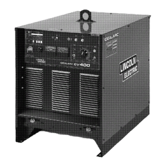
GENERAL MACHINE DESCRIPTION MACHINE OUTPUT CONTROL SWITCH “LOCAL” OR “REMOTE” The CV-400 is an SCR controlled three phase DC The machine output voltage can be controlled by power source. It is designed with a single range either the “OUTPUT CONTROL” on the machine con- potentiometer control. - Page 13 AUXILIARY POWER CONNECTIONS SOLID STATE CONTROL SYSTEM The power source is equipped to furnish nominally The Control PC Board is located behind the control 115 volt AC and 42 volt AC auxiliary power for operat- panel which hinges down for easy access to the ing wire feeding equipment, etc.
- Page 14 PARALLELING There are no provisions on the CV-400 to permit par- alleling. DIODE OPTION (Factory installed only) The CV-400 Diode option is required to utilize the cold start and cold electrode sensing features of the NA-3, NA-5 or NA-5R. When this option is not used with an NA-3, NA-5 or NA-5R, see the CV-400 / NA-3, CV-400 / NA-5 or CV-400 / NA-5R connection diagram for instructions on how to disable this circuit.
-
Page 15: Technical Specifications
TECHNICAL SPECIFICATIONS Model CV-400 Type K1346 Frequency 60 Hz Output Rating Amperes Volts NEMA EW1 IEC 974-1 Duty Cycle 60% 100% Output Range (Min.) 60A 12V (Max.) 500A 42V Max. O.C.V. Input Ratings 230/460 Standard Voltages 230/460/575 Single Voltages (Available) Rated Current 77A @ 400A 34V (230V) Input kVA 30.7 @ 400A 34V... -
Page 16: Installation
INSTALLATION APPLICATION LIMITATIONS There are no provisions on the CV-400 for paralleling, Safety Precautions and outdoor operations without rain sheltering is not recommended. WARNING ELECTRIC SHOCK can kill. LIMIT ON STACKING • Do not touch electrically live parts or WARNING electrode with skin or wet clothing. •... -
Page 17: Output Connections
REMOTE CONTROL ADAPTER CABLE (K864) CAUTION Failure to follow these instructions can cause immedi- C A B L E R E C E P TA C L E ( 6 S O C K E T ) S T R A I G H T P L U G ( 1 4 P I N ) T O P O W E R S O U R C E ate failure of components within the machine. -
Page 18: Installation Of Equipment Required For Recommended Processes
Refer to “115VAC and 42VAC Auxiliary Power and Control Connections” section for connector pin functions. A cover (Lincoln Electric Part Number S17062-3) is available for the unused 14-pin connector to protect it against dirt and moisture. For control cable with terminal strip connectors:... -
Page 19: Operating Instructions
OPERATING INSTRUCTIONS POWER SOURCE OPERATION Safety Precautions Duty Cycle and Time Period WARNING The CV-400 is rated at the following duty cycles: ELECTRIC SHOCK can kill. • Have an electrician install and service this equipment. Duty Cycle* Amps Volts • Turn the input power off at the fuse box before working on equipment. -
Page 20: To Set Polarity
OUTPUT CONTROL “LOCAL-REMOTE” SWITCH FRONT VIEW OF 14-PIN CONNECTOR RECEPTACLE The Output Control toggle switch on the control panel K = 4 2 labeled “Local-Remote” gives the operator the option J = 3 1 A = 3 2 of controlling the output at the machine control panel B = G N D I = 4 1 or at a remote station. -
Page 21: Maintenance
Terminal Strip Connections MAINTENANCE WARNING Terminal strip TS2 located behind the hinged control panel on the front of the power source supplies 115 ELECTRIC SHOCK can kill. VAC. A 10 amp circuit breaker protects this circuit. • Have an electrician install and service This 115 VAC is also available in the 14-pin connec- this equipment. - Page 22 TROUBLESHOOTING GUIDE Trouble Cause What To Do 1. Faulty input contactor (CR1). 1. Repair or replace. Input contactor (CR1 chatters). 2. Check input power. 2. Low line voltage. 1. Replace if blown - look for reason 1. Supply line fuse blown. Machine input contactor does not first.
- Page 23 Trouble Cause What To Do Machine has low output and no con- 1. Output Control “Local-Remote” 1. Check position of switch. trol. switch (S2) in wrong position. 2. Output Control switch faulty. 2. Check switch and replace if faulty. 3. Open in feedback circuitry. 3.
- Page 24 Trouble Cause What To Do Output control not functioning on 1. Output Control switch in wrong 1. Place switch in “Remote”. “Remote” control. position. 2. Faulty Output Control switch. 2. Check and replace if found faulty. 3. Faulty remote control poten- 3.
-
Page 25: Procedure For Replacing Pc Boards
Procedure for Replacing PC Boards CHECKING SNUBBER PC BOARD WARNING In case of an SCR malfunction or failure, the Snubber PC Board should be checked. Turn the machine off ELECTRIC SHOCK can kill. and remove the sides of the machine. Board is mount- •... - Page 26 REMOTE CONTROL CHECK resistance in both directions. An open diode will have an infinite or high resistance in both direc- Disconnect the remote output control and connect an tions and a good diode will have a low resistance ohmmeter across 75 and 76 and rotate the rheostat in in Step b.
- Page 27 POWER RECTIFIER BRIDGE DIAGRAM 1 PLUG TO SNUBBER BOARD ANODE To (+) side of capacitor bank CATHODE ANODE SCR1 SCR2 SCR3 GATE CATHODE SHUNT Gate leads plug to Control P.C. board To plug To T1 main transformer – –...
-
Page 28: Wiring Diagrams
WIRING DIAGRAM FOR CODES 10084 thru 10084, 11354, 11835 Enhanced Diagram – –... - Page 29 WIRING DIAGRAM FOR CODES 10087, 11087, 11088, 11089, 11055, 11836 CV-400 WIRING DIAGRAM L9270 L9270 – –...
- Page 30 NOTES CV400...
- Page 31 NOTES CV400...
- Page 32 Do not touch electrically live parts or Keep flammable materials away. Wear eye, ear and body protection. • • • WARNING electrode with skin or wet clothing. Insulate yourself from work and • ground. Spanish No toque las partes o los electrodos Mantenga el material combustible Protéjase los ojos, los oídos y el •...
- Page 33 Keep your head out of fumes. Turn power off before servicing. Do not operate with panel open or • • • WARNING Use ventilation or exhaust to guards off. • remove fumes from breathing zone. Spanish Los humos fuera de la zona de res- •...
- Page 34 • World's Leader in Welding and Cutting Products • • Sales and Service through Subsidiaries and Distributors Worldwide • Cleveland, Ohio 44117-1199 U.S.A. TEL: 216.481.8100 FAX: 216.486.1751 WEB SITE: www.lincolnelectric.com...
Need help?
Do you have a question about the 10084 and is the answer not in the manual?
Questions and answers