Table of Contents
Advertisement
Quick Links
Advertisement
Table of Contents

Subscribe to Our Youtube Channel
Related Manuals for GRAVOGRAPH LS1000 XP


Summary of Contents for GRAVOGRAPH LS1000 XP
- Page 1 OPERATING AND MAINTENANCE MANUAL LS1000 XP ENGRAVING LASER / CUTTING LASER...
-
Page 2: Table Of Contents
Table of contents A. Foreword ..............................5 1. Appreciation ............................5 2. Information ............................. 5 B. Legal notices ............................6 C. Regulation observance ..........................7 D. Required safety labels ..........................8 E. Introduction ..............................9 1. Presentation ............................9 2. Identification of the marking equipment ....................9 3. Work station safety .......................... - Page 3 „ Engraving table ..........................22 „ Cutting table ............................23 2. Rear view of the machine ........................24 3. Water chiller (only for 100W/150W laser sources) ................25 „ Front view ............................25 „ Rear view ............................25 Recommendations for installation ....................... 26 1. Physical installation ..........................26 2. Water chiller ............................27 3. Air extraction system (optional) ......................27 4.
- Page 4 L. Using the machine ..........................50 1. Switching on the PC / Switching on the machine ................. 50 2. Creating the composition ........................50 3. Setting the driver properties ......................... 50 4. Transferring the file ..........................51 5. Work table(s): Cutting or engraving ...................... 51 6. "Passthrough" function - Class 4 ......................52 7. Positioning the object to be engraved ....................
-
Page 5: Foreword
A. Foreword 1. Appreciation Thank you for choosing LS1000 XP - Gravograph. Gravotech is pleased to count you among the users of its engraving and traceability solutions. For help, contact Gravotech. For more information on products, visit www.gravograph.com website. 2. Information To ensure security and productivity, read this manual before starting-up the equipment. It provides details about the installation and use of the equipment. Keep this manual in case you need to refer to it. -
Page 6: Legal Notices
Gravotech, (iii) the integration of a control system and (iv) the connection to an external device. Such specifications' alterations may lead to the non-compliance of the Product with applicable rules and standards. Shall the Product be non-compliant, the person in charge of the Product's installation shall be responsible of the final workstation's compliance. In no event, Gravotech shall be liable for any damages arising from such non-recommended or unauthorized Product's alterations. It is precised that the warranty shall not apply in such case. Under no circumstances shall Gravotech be held liable for any indirect, incidental, special, consequential punitive or other similar damages, including any economic loss, loss of profit, loss of data or opportunity, whether or not foreseeable by or communicated to Gravotech, caused by this manual or the supply of Products or services concerned by the said manual. To the widest extent permitted by law, Gravotech shall only be held liable for direct damage arising from personal injury caused by a fault proven in its Product (including this manual). Gravotech® - Type3® - Propen™ - Technifor™ - Gravograph® is (are) a used, pending or registered trademark(s) of Gravotech group or one of its subsidiaries. The products and names of third party companies which appear in this manual are used solely for the necessary purposes of reference, and in particular for issues of compatibility. All the trademarks mentioned in this manual remain the property of their respective owners. Windows® is (are) a used, pending or registered trademark(s) of Microsoft Corporation. Postscript® is (are) a used, pending or registered trademark(s) of Adobe Systems Incorporated. M_LS1000 XP_EN_C... -
Page 7: Regulation Observance
C. Regulation observance Last updated: 06/2017 EC declaration of conformity or declaration of incorporation supplied with the machinery Type of machine Directives - Standards Dot peen marking: Machine - Machinery: 2006/42/EC XF500p, XF500m, Medrix Id, MR7000 - Low voltage: 2014/35/EU P5000PN, P5000EM, Impact, Impact eZ - EMC: 2014/30/EU - RoHS 2: 2011/65/EU Scribing marking: Machine M10 Jewel, M20 Pix, B-Engraver RingCube, TagCube, MedalCube Sharpening by grinding: Machine CG30, CG100 Bevelling: Machine B4, B6 Engraving by milling: Machine IM3, TXL M20, M20 Jewel, M20 ABC, M20 Pen, M20 Energy, M20 Beauty Cube M40, M40 Deep vice, M40 Gift, M40 ABC... -
Page 8: Required Safety Labels
Last updated: 12/2016 Required safety labels Shared labels LASER RADIATION Electrical hazard LS100 LS100 Ex Flammable LS100 energy materials LS900 LS900 XP LS1000 XP Hot surface Flammable materials LS100 Ex Fibre LS900 Fibre Hot surface Laser Solution Fiber-Series Laser Solution Hybrid-Series Laser Solution... -
Page 9: Introduction
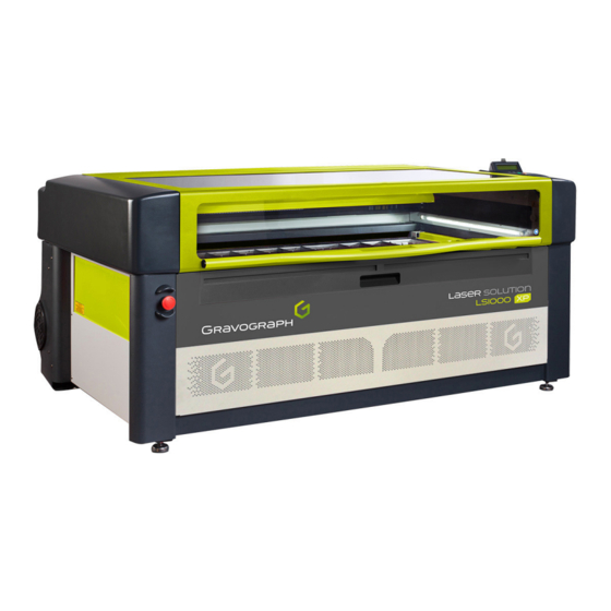
E. Introduction 1. Presentation The LS1000 XP is an engraving, marking and cutting machine equipped with a CO2 laser source. The 40W/60W/80W laser sources are air cooled. The 100W/150W laser sources are water cooled. A water chiller is supplied. This type of laser offers very high quality marking on a wide range of materials. 2. Identification of the marking equipment The marking equipment is identified by: • 1 identification plate on the rear face Have the model and serial number of the equipment available when contacting Gravotech. 3. Work station safety • Turn off the machine before beginning any cleaning, maintenance or repair procedure. • Never operate the machine near a cardiac pacemaker. • Never operate the machine without the protective covers properly mounted. • Never operate the machine if the doors are damaged or do not close properly. -
Page 10: X84; Water Chiller
Introduction „ Water chiller Never operate the LS1000 XP 100W/150W machine without a properly operating water chiller that is correctly configured, installed and maintained in good working order. In order to protect the chiller pump, it is strictly prohibited to operate it without demineralised water in the tank. To avoid damaging the pump, it is important to fill the tank before using it for the first time. • It is important to check that the demineralised water level is always adequate. Cooling capacity begins to decline when the demineralised water level falls below the green area (NORMAL) on the gauge. • Never drain the water tank while the chiller is in operation. -
Page 11: X84; Handling The Machine
Introduction „ Handling the machine • Never move or lift the machine without the assistance of lifting rings and an appropriate vehicle. Serious injury can occur if incorrect lifting techniques are used. • The head must be handled with the greatest care. • Never subject the bridge X of the machine to a magnetic field. • In the event of an extended period of non-use, unplug the power cable and protect the machine. • Never move the head manually unless the machine is jammed mechanically. • Never pour or spill liquid on the machine (drinks, cleaning products, etc.) except where recommended by Gravotech (Example: Lubrication). M_LS1000 XP_EN_C... -
Page 12: Unpacking
The machine should be carried in its packaging using a lifting system that can lift 500 kg (1 102.311 lb) or more. 1. Unpacking 1. Cut and remove the straps holding the 2 parcel(s) together (Support table) - (LS1000 XP). Support table LS1000 XP Water chiller (only for 100W/150W laser sources) 2. - Page 13 (1 person(s) on each side). 6. Cut and remove the packaging straps (LS1000 XP). Remove the cardboard. 7. Lift the machine by the straps using a hoisting system and place it on the support table (3 person(s) on each side).
-
Page 14: Package Contents
Unpacking 2. Package contents „ Package contents - Machine Machine: LS1000 XP Support table LS1000 XP 1 CD-ROM with user manual Toolbox Power cable USB cord „ Toolbox: Content 1 bottle(s) of cleaning solution 1 packet(s) of lens cleaning wipes 1 packet(s) of cotton buds for mirrors Driver Ball-tip hex key Brush Set of 6 keys Autofocus adjustment gage Compressed air hose for air assist (Length: 100 mm (3.937 in) - Tube diameter: 4 mm (0.157 in)) 10. -
Page 15: X84; Package Contents - Water Chiller - Only For 100W/150W Laser Sources
Unpacking „ Package contents - Water chiller - only for 100W/150W laser sources Water chiller Cardboard box Black hose Blue hose „ Cardboard box: Content Spanner for the water filter Roll of Teflon Fuse M_LS1000 XP_EN_C... -
Page 16: Laser Safety
G. Laser safety 1. Recommendations and safety regarding laser devices „ Personnel safety THIS MACHINE HAS A CLASS 4 LASER BOXED IN A CLASS 1 CASING. THIS MACHINE IS CONSIDERED AS CLASS 2M DUE TO ITS VISIBLE DIODE LASER (Red). • The machine is considered as Class 1 when the door is closed. In this case, the security enclosure of the LS1000 XP is locked and sealed against potential Laser radiation emissions under normal working and safety conditions. The modification of locking systems, or the removal of these systems or labels designed for safety, will... -
Page 17: Using The Passthrough Feature - Class 4
Laser safety 2. Using the Passthrough feature - Class 4 When one of the retractable doors is open, the machine is no longer considered as Class 1 (in a secured area) but as Class 4. A controlled laser zone should be defined. Operators and service personnel must receive laser safety training. Carefully read the "Laser Safety" chapter. For help, contact Gravotech. It is mandatory that the operator wear eye protection with the suitable filter lenses. (D LB4 @ 10600 nm).Any person standing in proximity to the laser must obey the same safety instructions. -
Page 18: Work Station Safety
Laser safety 3. Work station safety „ Proposed warning label at the entrance to the laser controlled zone (Using the Passthrough feature - Class 4) Specific hygiene and safety instructions - Personnel laser radiation protection Concerned industrial use installation: Use: Installation: Restricted area The room in which this sign is posted is defined as a restricted laser area: in normal production phase (1) maintenance and setting phase (1) ................(1) Regulation in the restricted area Access to the restricted laser area is regulated. Only competent personnel having... -
Page 19: X84; General Instructions
Laser safety „ General Instructions Avoid any exposure to laser radiation. Do not put hands or an object in the laser beam's trajectory. Never stare into the primary laser beam. Do not direct the beam towards other persons, openings or windows. Avoid direct eye exposure to diode laser beam. -
Page 20: Potential Hazards Related To Materials Worked With
Laser safety 4. Potential hazards related to materials worked with „ Fumes and toxic particles Laser marking certain materials emits dangerous fumes and particles that may be toxic and/or damage the equipment. In this case, adapt an extraction system (with filtration if necessary) to the marking station. The user must check the compatibility of marked or engraved materials with the laser type. -
Page 21: X84; Examples Of Secondary Radiation Risks
Laser safety „ Examples of secondary radiation risks The use of a class 4 laser device can generate: • A risk of fire or explosion due to materials or inflammable substances • UV radiation • X rays • High intensity visible light when marking on certain materials M_LS1000 XP_EN_C... -
Page 22: Description Of The Machine
H. Description of the machine 1. Front view of the machine „ Engraving table Air assist: Adjustment button LCD screen Green light -Red light Keyboard Glass door Head On / Off switch Ruler: Y Emergency stop push button 10. "Passthrough" retractable doors 11. Front door 12. Collection tray 13. Engraving table 14. Frame 15. -
Page 23: X84; Cutting Table
Description of the machine „ Cutting table Removable blades Cutting table M_LS1000 XP_EN_C... -
Page 24: Rear View Of The Machine
Description of the machine 2. Rear view of the machine Each connection meets one of the following safety levels: Dangerous voltage. SELV (Safety extra-low voltage). Opening for air evacuation hose to air extraction system Pneumatic connection for tube - Air assist Input/output link: Air extraction system - SELV Standard input/output link - SELV Do not use (The protective cap should not be removed under any circumstances.) Port: USB - SELV Power inlet / outlet - Dangerous voltage -Only for 100W/150W laser sources: Hot water outlet (OUT) leading to the water chiller. Cooled water intake (IN) coming from the water chiller. M_LS1000 XP_EN_C... -
Page 25: Water Chiller (Only For 100W/150W Laser Sources)
Description of the machine 3. Water chiller (only for 100W/150W laser sources) An industrial chiller is supplied with the machine, for the purposes of water cooling the 100W/150W laser sources. „ Front view Temperature controller Water pressure gauge Insufficient flow alarm (Red light) Normal flow (Green light) Air inlet (Air filter) General stop button (Power switch) „... -
Page 26: Recommendations For Installation
I. Recommendations for installation The physical installation and connections must be done by a Gravotech approved technician. Turn off the machine before any intervention. 1. Physical installation • Place the machine on a horizontal, stable and clean surface that can support 300 kg (661.387 lb) or more. • Check that the engraving table is level in both directions (Adjust with a spirit level.) • Place the machine in a clean, ventilated environment. Choose the location that offers the shortest and most direct route to the air extraction system (See: "Air extraction system (optional) "). • Avoid small, confined, unventilated spaces. Some materials continue to emit gases for a few minutes after laser marking or cutting. The presence of these materials in a confined, unventilated room could contaminate the room. -
Page 27: Water Chiller
Recommendations for installation 2. Water chiller The 100W/150W laser sources must be cooled by means of a water chiller with the capability to control a minimum flow and a maximum water temperature. A water chiller is supplied. The cooling parameters are preset in order to guarantee water temperature regulation with the triggering of a temperature alarm in the event of over-temperature. -
Page 28: Air Assist (Option: Air Compressor)
Recommendations for installation 4. Air assist (option: Air compressor) The operation of the air assist system (blown air) requires the use of an air compressor (not supplied). Configuration: Air flow rate: 40 l/mn(Minimum) Use the air assist system integrated into the extractor LE190HP (optional). Use the compressed air hose supplied to connect the machine to the air compressor. Pneumatic connection for tube - Air assist Compressed air hose for air assist (Length: 100 mm (3.937 in) - Tube diameter: 4 mm (0.157 in)) M_LS1000 XP_EN_C... -
Page 29: Requirements
Recommendations for installation 5. IT requirements Hardware Minimum configuration of the PC Recommended configuration Microprocessor Dual Core Quad Core Frequency 2.7 GHz 2.4 GHz 2 Go / GB 4 Go / GB Hard disk 3 Go / GB available 6 Go / GB available DVD: Internal drive 16X DVD-ROM 16X DVD-ROM 2 button(s) 2 button(s) + Thumbwheel - Mouse Windows®-compatible Windows®-compatible... -
Page 30: Connecting/Disconnecting The Water Chiller
Recommendations for installation 7. Connecting/disconnecting the water chiller „ Connecting the water chiller 1. Fill the tank with demineralised water until the water level reaches the green area (NORMAL) on the gauge. To avoid any contamination, it is recommended that a biocide be added to the demineralised water. -
Page 31: X84; Disconnecting The Water Chiller (Shipping Position)
Recommendations for installation „ Disconnecting the water chiller (shipping position) 1. Switch off the chiller. 2. Disconnect the hoses from the connectors on the machine. 3. Connect the 2 hoses together. M_LS1000 XP_EN_C... -
Page 32: Electrical Installation
Avoid the installation of manual or automatic switching systems on the same mains power line as the machine (relays, timers, programmers, automatic circuit-breakers, automatic switches, etc.). • Check that devices in the vicinity of the machine meet the standards for electromagnetic interference. Read the technical data sheet for each device. If they are non-compliant, move them as far away from the machine as possible. • Use the Gravograph accessories. Always switch the machine off before connecting or disconnecting a cable or optional accessory. M_LS1000 XP_EN_C... -
Page 33: Connections - Installation
J. Connections - Installation 1. Power supply connection - Water chiller Power inlet / outlet (with fuse) - Dangerous voltage Power cable General stop button (Power switch) 1. Connect the power cord to the chiller socket and then plug into the mains socket. To cut the power supply to the chiller in the event of a major problem, unplug the power cord or actuate the general stop button on the chiller. „ Switching on the chiller 1. -
Page 34: X84; Resolution Of The Problems: Water Chiller
Connections - Installation „ Resolution of the problems: Water chiller If the chiller does not switch on: • Check that the power cord is connected correctly, on both the chiller side and mains side. • Check that there is power to the mains plug. The chiller switches on but encounters a problem: • Check that the intake and outlet valves are correctly opened. • Check the water level in the tank. • Check that the water hoses are correctly connected between the chiller and the laser machine. M_LS1000 XP_EN_C... -
Page 35: Power Supply Connection - Machine
Connections - Installation 2. Power supply connection - Machine Rear view of the machine Input/output link: Air extraction system - SELV Standard input/output link - SELV Power cable Power inlet / outlet - Dangerous voltage 1. Connect the machine/extraction system link cable on both sides. 2. Tighten the connector screws using the 3.5 screwdriver. Make sure the connector screws are properly tightened to prevent the cables from becoming disconnected while the machine is switched on. -
Page 36: X84; Using The Plc Function (User Standard Inputs/Outputs)
Connections - Installation „ Using the PLC function (User standard inputs/outputs) Before making any "user standard input/output" connections, check that the electrical and electronic characteristics of the different inputs and outputs are respected. Incorrect connection could permanently damage the machine electronics. Using the PLC function means that it is not just a matter of considering the machine on its own in order to ensure operator safety. - Page 37 Connections - Installation Input / Output characteristics (Sub-D15 connector) Number Function Type: Comments Output NPN Maximum current: 50 mA Output NPN Maximum current: 50 mA Output NPN Maximum current: 50 mA Output NPN Maximum current: 50 mA Available for powering the loads Maximum current: 200 mA switched by the NPN outputs (O1 - dry contact TTL-compatible...
- Page 38 Connections - Installation Example of wiring for an Input (I1) Control Unit Example of wiring for an Output (O1) - 24 V inductive load Control Unit Example of wiring for an Output (O1) - 5 V inductive load Control Unit When connecting inductive charges use an anti-parasite protection and a freewheeling diode to avoid damaging the Outputs. M_LS1000 XP_EN_C...
-
Page 39: X84; Switching On The Machine
Check that the water cooling circuit is operating properly. Check that water cannot leak onto the electronic components of the machine. 1. Place the switch in the "I" position (On). The screens must follow on from one another: L01 SETUP FPGA << GRAVOGRAPH >> FPGA X.XX LCD SOFT X.XX 32 Mo BOOT X.XX... -
Page 40: X84; Power Down: Machine - Water Chiller
Connections - Installation „ Power down: Machine - Water chiller 1. Machine: Put the On/Off switch in the "O" (Off) position. 2. Water chiller: Set the general stop button to the "O"(Stop) position. Switch off the machine in the following situations: • when the operator is permanently leaving the machine • in the event of physical damage (something is dropped on the machine, fire, a liquid is spilled on the machine, etc.) •... -
Page 41: Machine / Pc Connection
Connections - Installation 3. Machine / PC connection The machine installation and usage procedure is based on a PC-type computer running Windows®. For help, contact Gravotech. Switch off the PC and the machine. Follow the connection procedure for the type of link cable supplied with the machine. The machine is supplied with a USB cable. „ Machine / PC connection (USB connection) 1. Connect the USB cable to the machine's USB port. 2. Connect the USB cable to the PC's USB port. M_LS1000 XP_EN_C... -
Page 42: Operating Instructions For The Machine
K. Operating instructions for the machine 1. Control panel The machine control panel is used to easily access to all the controls for cutting and engraving/marking. Selection of the next file Positioning pointer Air assist Air extractor Autofocus Start - Start marking Cancel Pause "Check" key 10. Air assist adjustment 11. Green light - Red light 12. Selection of the previous file 13. Joystick 14. Focus adjustment M_LS1000 XP_EN_C... - Page 43 Operating instructions for the machine Selection of the next file Display of next file in machine memory, which becomes current file Activation of a very low power laser beam, providing an indication of the Positioning pointer marking position on the plate Air assist Activation of air assist during marking Air extractor Activation of air extraction and filtration during marking Autofocus Automatic focus adjustment (automatic Z Ref.) Start Start-up engraving. Start marking Exit from menu without applying change to last parameter Cancel Return to reception, during a pause, during end of reception, during end of engraving Pause Marking suspended. Access to the different menus Exit from current menu "Check" key Move to next screen...
-
Page 44: X84; Indicator Light(S)
Operating instructions for the machine „ Indicator light(s) The status of the lights varies depending on the machine activity. Green light Status Description Machine initializing End of file processing and return to original position Machine ready to receive a file off Interruption during file processing Pause Red light Status Description Machine initializing Machine ready to receive a file off Pause flashing Marking in progress 2. Description of the human-machine interface „ Joystick The arrow keys (joystick) are used to move the X-Y axes manually. The joystick is mainly used for positioning the head directly above the material to be engraved. -
Page 45: X84; Access To The Different Menus
Operating instructions for the machine This key is used to adjust the height of the engraving table. The operator can adjust the vertical position anywhere within the area. 1. To switch to vertical movement: Press the key: 2. Press and hold the key(s). The table moves vertically to the desired position. 3. Release the key(s). 4. To confirm, press the key: The vertical position is saved. „ Access to the different menus To access the machine menu(s): 1. Switch on the machine. Wait until the following message appears on the screen: <READY TO RECEIVE >... -
Page 46: Control Panel: Water Chiller (Only For 100W/150W Laser Sources)
Operating instructions for the machine 3. Control panel: Water chiller (only for 100W/150W laser sources) RST: "Check" key SET: "Function adjustment" key. Red light D1 Status Meaning indicator light on The controller is operating in intelligent control mode. Indicator light not The controller is operating in constant temperature control mode. illuminated The controller is operating in setting adjustment mode or is displaying ambient temperature values The light flashes. in the room. -
Page 47: X84; Temperature Alarm Function
Operating instructions for the machine „ Temperature alarm function When a temperature alarm is triggered, the error code and the temperature are displayed on-screen simultaneously. To stop the audible alarm signal, press one of the controller keys. The alarm remains displayed until its cause has been eliminated. Error Meaning Maximum ambient temperature exceeded Maximum water temperature exceeded Water temperature below the minimum Malfunction of the ambient temperature sensor Malfunction of the water temperature sensor... - Page 48 Operating instructions for the machine Control parameters Range of Initial setup Order Code Functions Notes values Constant Constant temperature 5 ─› 40 temperature control Temperature -15 ─› +5 Intelligent control difference values Constant Cooling hysteresis 0.2 ─› 3.0 temperature control 0: Constant temperature Control mode 0 ─› 1 control 1: Intelligent control Alarm: Maximum water temperature...
-
Page 49: X84; Advanced Parameters
Operating instructions for the machine „ Advanced parameters The parameters of the industrial chiller supplied with the 100W/150W machines are preset (Initial setup). It is not necessary to change these parameters. 1. Hold the key down. Press the key. <SET> (For 5 second(s)). 2. -
Page 50: Using The Machine
L. Using the machine Example: Engraving a keyring 1. Switching on the PC / Switching on the machine 1. Switch on the PC. 2. Wait until start-up is complete. 3. Switch on the machine. 2. Creating the composition 1. Adjust the page size to the maximum size of the engraving area in the graphics software (LS1000 XP: 1220 mm (48.031 in) x 610 mm (24.016 in)). -
Page 51: Transferring The File
Using the machine 4. Transferring the file 1. Check that the USB cable is correctly connected at both ends. 2. Check that the machine screen says "Ready to receive". 3. Click on: Print.. (Graphics software). Or Click on the icon: ,Click on: (GravoStyle/LaserStyle). -
Page 52: Passthrough" Function - Class 4
Using the machine 6. "Passthrough" function - Class 4 Observe laser safety rules (See: "Using the Passthrough feature - Class 4 "). To mark objects exceeding the standard dimensions of the working surface: 1. Open one or more of the retractable doors. 2. Place the object in position by passing it through the "Passthrough" openings. 7. -
Page 53: Using The Air Assist Nose -Option
Using the machine 8. Using the air assist nose -option 1. Fit the air assist nose onto the head of the machine. 2. Disconnect the air assist tube from the connector on the head and connect it to the air nose connector. -
Page 54: Start-Up Engraving
Using the machine 10. Start-up engraving 1. Switch on the air extraction system. 2. Activate the air extractor: Press the key. (Control panel). 3. Check that the object is correctly positioned in the engraving area. 4. Check the focus. 5. Check that the door is closed. 6. -
Page 55: Removing And Reloading Material
Using the machine 11. Removing and reloading material The laser beam is shut off once the machine has finished processing the material. The head goes back to the origin (top left corner). Before opening the door, wait a few seconds for any remaining fumes emitted during the marking or cutting process to be removed by the extraction system. In the L-Solution driver, it is possible to enter a timeout value to set a delay before the air extraction system stops when marking is finished. Open the front door. Remove the material. The collection tray allows cut pieces to be recovered. Collection tray Cutting table Load the next material. If it is the same material as the one before and the same file is being executed, close the door. Start-up engraving: Press the key. M_LS1000 XP_EN_C... -
Page 56: Adaptable Accessories
M. Adaptable accessories List of accessories available upon request 1. Cylinder attachment Used to mark cylindrical parts thanks to a rotary marking device. This accessory is designed to hold glasses, mugs, cups, etc. Always switch the machine off before connecting or disconnecting the cylinder attachment (optional). This equipment is supplied with: • Mount(s) (x 2) • 1 cone(s) attached to the motorized end of the element • 1 inverted cone(s) attached to the adjustable end of the element This accessory is placed on the engraving table. -
Page 57: Preventive Maintenance
N. Preventive maintenance 1. General maintenance Unplug the power supply plug before beginning any cleaning or maintenance operation. The mains power cable must be replaced immediately if it is cut or crushed, cracked or a conductor is stripped bare. The machine's maintenance needs depend on the type of material used, the quantity of material removed, frequency of operation, environment and the effectiveness of the air extraction system. It is the user's responsibility to define them. -
Page 58: Cleaning The System
Preventive maintenance 3. Cleaning the system „ Engraving table 1. Switch off the machine. Unplug the machine. 2. Open the front door. 3. Remove any dust or debris inside the machine using a vacuum cleaner. Do not use a blower. 4. Clean the surface of the engraving table with a soap solution, alcohol or acetone and paper towels. Never pour or spray solution into the machine. -
Page 59: Optics Maintenance
Preventive maintenance 4. Optics maintenance Visually inspect the mirrors, the laser beam window and the lens used for focusing, known as the focal lens, at least 1 time(s) a day. Do not remove the lenses or mirrors to clean them. Never touch an optic with your fingers. Acids in the skin could destroy the coating on the optics. Use the Gravotech accessories. „ Mirror(s) / Lens(es) Check the mirrors and lenses. Clean them with a lens cleaning wipe (Access them through the mirror access.) Mirror access Lens(es) M_LS1000 XP_EN_C... -
Page 60: Removing And Cleaning The Z Auto Sensor
Preventive maintenance 5. Removing and cleaning the Z Auto sensor Do not touch the switch and its fastening screws. Do not touch the fastening screw of the sensor hook. 1. Loosen the knurled screw without removing it. Knurled screw Switch fastening screws Switch Z Auto sensor Sensor hook Mounting screw(s) 2. - Page 61 Preventive maintenance 3. Remove the Z Auto sensor from the bottom. Z Auto sensor 4. Clean the Z Auto sensor with a clean dry cloth. 5. Place the Z Auto sensor back into position. Sensor hook Z Auto sensor 6. Lower the sensor hook. Knurled screw Z Auto sensor Sensor hook 7.
-
Page 62: Autofocus Adjustment
1. Switch off the machine. 2. Close the door of the machine. 3. Switch on the machine. The screen below appears: L01 SETUP FPGA The machine emits an audible signal. The following screen is displayed for 3 seconds: << GRAVOGRAPH >> FPGA X.XX LCD SOFT X.XX 32 Mo BOOT X.XX 4. While this screen is displayed, press the key: 5. - Page 63 Preventive maintenance Head The screen below appears: Z ADJUSTMENT JOYSTICK Z = 20.00 9. Open the front door. 10. Place the autofocus adjustment gage in position on the engraving table, under the lens support of the head. Autofocus adjustment gage 11. Move the engraving table upwards until the lens support comes into contact with the gage. Autofocus adjustment gage Lens support 12.
- Page 64 ALIGNMENT MODE 16. To cancel/exit, press the key: LASER SETTINGS TICKLE RE-ALIGN MACHINE USING TIME 17. To cancel/exit, press the key: The following screen is displayed for 3 seconds: << GRAVOGRAPH >> FPGA X.XX LCD SOFT X.XX 32 Mo BOOT X.XX The screen below appears: <READY TO RECEIVE >...
-
Page 65: Setting Point Zero (Origin)
Preventive maintenance 7. Setting point zero (Origin) The screen below appears: L01 SETUP FPGA The machine emits an audible signal. The following screen is displayed for 3 seconds: << GRAVOGRAPH >> FPGA X.XX LCD SOFT X.XX 32 Mo BOOT X.XX 1. While this screen is displayed, press the key: 2. Select the following menu:... -
Page 66: Technical Specifications
O. Technical specifications 1. Physical characteristics Dimensions (L x w x h): Machine 1660 mm (65.354 in) x 1160 mm (45.669 in) x 800 mm (31.496 in) Net weight: Machine Maximum: 220 kg (485.017 lb) Dimensions (L x w x h): Machine + 1810 mm (71.260 in) x 1330 mm (52.362 in) x 1040 mm (40.945 in) Packing Weight: Machine + Packing Maximum: 280 kg (617.294 lb) -
Page 67: Environment
Technical specifications 4. Environment Operating temperature 10 °C (50 °F) - 35 °C (95 °F) Storage temperature -5 °C(23°F) - 45 °C (113 °F) Humidity level: 5 - 85 % 5. Laser characteristics Classification CDRH: Class 2M (Pass-through: Class 4) Source CO2 / c 40 W - c 60 W - ti 80 W - ti 100 W - E 150 W Wavelength: 10640 nm (10.6 μm) Lens(es) -
Page 68: Firmware Characteristics - Driver
8. Firmware characteristics - driver Languages (Firmware) FR - EN - DE - IT - ES - NL - BR - HU - TR - PL - JP File format Gravograph binary encoding RAM (Firmware) 32 Mo / MB - Storage of multiple jobs Driver version Minimum:7.04 (firmware: 3.41) -
Page 69: Appendix: Engraving Menu
P. Appendix: Engraving menu Last updated: 03/16 To access the machine menu(s): 1. Switch on the machine. SET UP FPGA << GRAVOGRAPH >> FPGA X.XX LCD SOFT X.XX 32 Mo BOOT X.XX Waiting time: 3 s <READY TO RECEIVE> 2. Press the key:... -
Page 70: Parameters" Sub-Menu
Appendix: Engraving menu 1. "Parameters" sub-menu Used to manage the parameters for the current job. PARAMETERS FILE INFO CONFIGURATION POWER SPEED DPI-X DPI-Y 2. "File" sub-menu Used to manage the files imported into the machine (Deleting files...). PARAMETERS FILE INFO CONFIGURATION 001 FILENAME1 > DELETE THIS FILE DELETE ALL 90 % FREE MEMORY 3. "Info" sub-menu Used to view the information related to the imported files.
Need help?
Do you have a question about the LS1000 XP and is the answer not in the manual?
Questions and answers
When I draw a 1" x 1" square in Gravostyle the laser will cut the square but it will come out smaller at .875" by .875" How do I fix this? My machine is a LS1000 xp 150watt
If the GRAVOGRAPH LS1000 XP is cutting a 1" x 1" square smaller at 0.875" x 0.875", the issue may be related to calibration. To fix this:
1. Check and Clean the Machine – Ensure there is no debris affecting movement by cleaning the engraving area and optics as recommended.
2. Verify the Settings – Check the software settings and ensure the correct dimensions are entered.
3. Calibrate the Axis – If the scaling is incorrect, recalibrate the X and Y axes to ensure accurate cutting.
4. Inspect Mechanical Components – Ensure belts, rails, and movement systems are functioning correctly without slippage or obstruction.
5. Contact Gravotech Support – If the issue persists, a technician may be required for further calibration or repair.
Regular maintenance and proper calibration should resolve size discrepancies.
This answer is automatically generated