Table of Contents
Advertisement
Quick Links
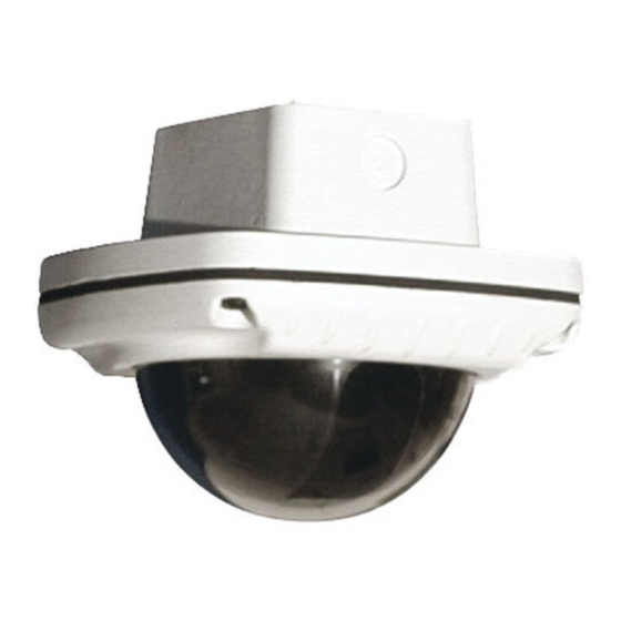
WS2(T/C)-XXXX / WS4-XXXX
REVISION DATE: 02-02-2009
TABLE OF CONTENTS
Cable and Power Guidelines
Exploded View WS2
Replacement Parts WS2
Exploded View WS4
Replacement Parts WS4
(Detailed info on Page 12)
This chart shows the proper current needed for power supplies for
Warrior Series cameras. Use Class 2 Power only. Output voltage
must be between 12-28 VDC or 15-28 VAC.
Depending on the voltage being used, refer to one of the formulas
below to select the correct power supply for cameras connected in
parallel (positive to positive, negative to negative):
INSTALLATION PREPARATION
1, 12
1. Determine the mounting location. Be sure that you'll be
mounting to a secure wall or ceiling. We also recommend
1
that for outdoor applications the housing be mounted in a
1
protected area.
2
2
2. Complete all wire and conduit runs prior to installation.
2
3
3. The WS2 and WS4 are designed to be mounted in a
standard deep double-gang box.
3
5
4. IMPORTANT REMINDER: For outdoor applications it is
5
strongly recommended that you use sealant. Place a light
6
bead of sealant around the perimeter of the back of the
7
housing and around the head of each screw connecting the
housing to the double-gang box.
8
9
10
INSTALLATION PROCEDURE
11
12
1. Mount a double-gang box (not provided) using standard proce-
dures. Pull power and video wires through the gang box.
13
14
2. Using the security tool provided, loosen the four security
fasteners and remove the housing top.
3. Remove the bracket assembly by removing the (2) 10-32 screws
(Figure 1).
4.2W
4.8W
Figure 1
PRODUCT INSTRUCTIONS
NOTE: The housing top is held to the base by a lanyard.
NOTE: The camera is connected to the power board. Be
careful not to pull the wire loose.
© 2009, Videolarm, Inc. All Rights Reserved
Advertisement
Table of Contents

Related Manuals for Moog Videolarm WS2 Series

Summary of Contents for Moog Videolarm WS2 Series
-
Page 1: Table Of Contents
81-IN5236-06154 WARRIOR 2 & 4 WS2(T/C)-XXXX / WS4-XXXX REVISION DATE: 02-02-2009 PRODUCT INSTRUCTIONS TABLE OF CONTENTS INSTALLATION PREPARATION Cable and Power Guidelines 1, 12 1. Determine the mounting location. Be sure that you'll be mounting to a secure wall or ceiling. We also recommend Installation Preparation that for outdoor applications the housing be mounted in a Installation Procedure... -
Page 2: 81-In5236-06154 Warrior 2
WIRING (Figure 2) Terminal Connector Power Board Use Class 2 Power only. Input voltage must be between 12-28 VDC or 15-28 VAC. 1. Connect the output of your Class 2 Power Supply to the terminal connectors on the PC Board inside the housing. Refer to the Troubleshooting section later in this instruction sheet for more information. -
Page 3: Camera Focusing
Auto Iris Lens: 10-32 x 3/8" screws NOTE: THE AUTO IRIS LENS IS SET AT THE FACTORY. Thumb screws for pan adjustment for angle adjustment Camera cradle • IF YOU EXPERIENCE VIDEO TOO LIGHT OR DARK AUTO IRIS ADJUSTMENT MAY BE NEEDED. SEE THE TROUBLESHOOTING SECTION FOR ADJUSTMENT INFORMATION. - Page 4 SERIAL NUMBERS BEGINNING WITH MC MC CAMERA DIP SWITCH SETTINGS CHART The operational settings for the camera are defi ned by ten dip SWITCH SETTING DEFINITION switches located on the PC Board (Figure 9). Moving the switches to Flickerless Mode Setting this switch to "On"...
-
Page 5: Completion Of Installation
COMPLETION OF INSTALLATION SERIAL NUMBERS BEGINNING WITH CB NOTE: This hi-res color camera uses a 1/4" chip and a 3-6mm 1. A cardboard template is included to test the adjustment of your auto iris lens. It is comparable to a 1/3" chip using a lens/bracket setup before reattaching the housing top. -
Page 6: Nvt Instructions
ADDENDUM 1 Wiring Notes UNSHIELDED TWISTED PAIR Wire — What to DO VIDEO WIRING 1. DO use point-to-point Unshielded Twisted Pair wire, gauge 24 or thicker, stranded or solid, Category 2, 3, 4, or 5. NOTE: The customer must purchase the Video Transceiver from 2. -
Page 7: Ifs Instructions
ADDENDUM 2 Unshielded Twisted-Pair Wire Gauge (AWG) Unshielded Twisted-Pair Wire Gauge (AWG) Cable Cable Distance IFS FIBER CONNECTION 250 ft 250 ft 300 ft 300 ft 400 ft 400 ft 500 ft 500 ft NOTE: The customer must purchase the Receiver from IFS. Part 600 ft 600 ft number are:... -
Page 8: Warranty Information
IMPORTANT SAFEGUARDS SAFETY PRECAUTIONS 1. Read Instructions - All the safety and operating instructions should be read before the unit is operated. CAUTION 2. Retain Instructions - The safety and operating instructions should be retained for future reference. RISK OF ELECTRIC SHOCK! 3. -
Page 9: Service And Safeguard Information
TROUBLESHOOTING PICTURE IS CLEAR, LOW OR NO COLOR; PICTURE IS DARK OR GRAINY IN GOOD If you experience problems with the camera picture please check LIGHTING CONDITIONS these simple troubleshooting procedures for possible solutions before calling technical support. The auto iris lens is set at the factory. If you experience video STATIONARY OR SCROLLING HORIZONTAL too light or dark you can manually adjust using the auto iris LINES ON SCREEN... - Page 10 If the voltage is greater than 1/2 volt, use an amplified receiver, NVT TROUBLESHOOTING such as the NV-652R, NV-862R, or NV-1662R. If you are experiencing problems, attempt to simplify your setup. Test Alternately, remove the ground at one end (usually at the camera each cable segment separately.
-
Page 11: Cable And Power Guidelines
CABLE AND POWER GUIDELINES This chart shows the proper current needed for power supplies for Warrior Series cameras. Use Class 2 Power only. Input voltage must be between 12-28 VDC or 15-28 VAC VOLTAGE CURRENT POWER 12 VDC 350mA 4.2W 24 VAC 202mA 4.8W... - Page 12 WS2 - Exploded Diagram - 13 -...
- Page 13 WS2 - Replacement Parts List Part Number Description RPWS2010 WARRIOR 2 & 4 BASE ASSEMBLY RPWS2020 WARRIOR 2 & 4 CARRIAGE ASSEMBLY KIT NTSC BOARD CAMERAS RPWS1041F WARRIOR 1 & 2 STANDARD RES, BLACK & WHITE, FIXED CAMERA KIT RPWS1041V WARRIOR 1 &...
- Page 14 WS4 - Exploded Diagram - 15 -...
- Page 15 WS4 - Replacement Parts List Part Number Description RPWS2010 WARRIOR 2 & 4 BASE ASSEMBLY RPWS2020 WARRIOR 2 & 4 CARRIAGE ASSEMBLY KIT NTSC BOARD CAMERAS RPWS3041F WARRIOR 3 & 4 STANDARD RES, BLACK & WHITE, FIXED CAMERA KIT RPWS3041V WARRIOR 3 &...
- Page 16 Product Registration/Warranty Thank you for choosing Videolarm. We value your patronage and are solely committed to providing you with only the highest quality products available with unmatched customer service levels that are second-to-none in the security industry. Should a problem arise, rest assure that Videolarm stands behind its products by offering some of the most impressive warranty plans available: 3 Years on all Housings, Poles, Power Supples, and Accessories and 5 Years on all camera systems (SView, QView, Warriors), and InfraRed Illuminators.
Need help?
Do you have a question about the WS2 Series and is the answer not in the manual?
Questions and answers