
Related Manuals for Westinghouse ETL-ES-Troy-WH14


Summary of Contents for Westinghouse ETL-ES-Troy-WH14
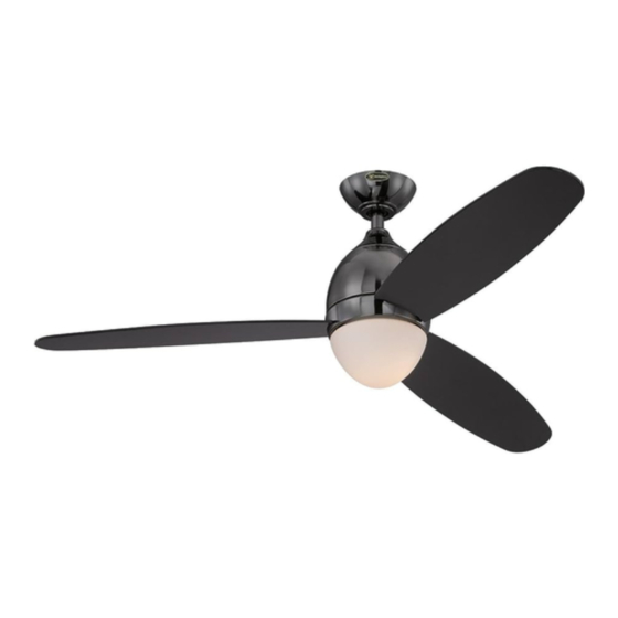
- Page 1 ETL-ES-Troy-WH14 OWnEr'S ManuaL ManuaL dEL uSuariO Troy Please write model number here for future reference: / Por favor, incluya el número del modelo aquí para futura referencia: net Weight: 16.28 LBS Peso neto: 7.4 KGS...
-
Page 2: Safety Tips
ETL-ES-Troy-WH14 SafETy TiPS OBSErVE THE fOLLOWinG: rEad and SaVE THESE inSTruCTiOnS WarninG: TO rEduCE THE riSK Of firE, ELECTriC SHOCK, Or PErSOnaL inJury, MOunT TO OuTLET BOX MarKEd 'aCCEPTaBLE fOr fan SuPPOrT Of 15.9 KG (35 LBS) Or LESS' and uSE MOunTinG SCrEWS PrOVidEd WiTH THE OuTLET BOX and/Or SuPPOrT dirECTLy frOM BuiLdinG STruCTurE. -
Page 3: Consejos De Seguridad
ETL-ES-Troy-WH14 COnSEJOS dE SEGuridad HaGa LO SiGuiEnTE: LEa y GuardE ESTaS inSTruCCiOnES adVErTEnCia: Para rEduCir EL riESGO dE inCEndiO, dESCarGa ELÉCTriCa O HEridaS GraVES PErSOnaLES, MOnTE En una CaJa dE EMBuTir rOTuLada “adECuada Para VEnTiLadOrES dE 15,9 KG (35 LB) O MEnOS” uTiLiZandO LOS TOrniLLOS dE MOnTaJE inCLuidOS COn La CaJa dE EMBuTir y/O MOnTE dirECTaMEnTE En La ESTruCTura dEL EdifiCiO La MayOrÍa dE LaS CaJaS dE EMBuTir uTiLiZadaS .nOrMaLMEnTE COn arTEfaCTOS dE iLuMinaCiÓn nO SOn adECuadaS Para VEnTiLadOrES y dEBErÍan SEr rEEMPLaZadaS. - Page 4 ETL-ES-Troy-WH14 fEaTurES CaraCTErÍSTiCaS DOWNROD INSTALLATION INSTALACIóN CON VARILLA VERTICAL For normal ceilings Para techo normales...
- Page 5 ETL-ES-Troy-WH14 PrEParinG fOr inSTaLLaTiOn anTES dE La inSTaLaCiÓn Use metal outlet box suitable for fan support (must support 35 lbs). Before attaching fan to outlet box, ensure the outlet box is securely fastened by at least two points to a structural ceiling member (a loose box will cause the fan to wobble).
- Page 6 ETL-ES-Troy-WH14 MOunTinG BraCKET inSTaLLaTiOn MOunTinG OPTiOnS inSTaLaCiÓn COn SOPOrTE dE MOnTaJE OPCiOnES dE MOnTaJE Choose a MOunTinG OPTiOn Elija una OPCiÓn dE MOnTaJE nOrMaL dOWnrOd OPTiOn If installing downrod supplied with fan, proceed to page 7, step#5. OPCiÓn COn VariLLa VErTiCaL Para TECHO nOrMaL Si instala la varilla vertical incluida con el ventilador, proceda a la página 7, paso 5.
- Page 7 ETL-ES-Troy-WH14 nOrMaL dOWnrOd OPTiOn OPCiÓn COn VariLLa VErTiCaL Para TECHO nOrMaL Place downrod assembly into canopy (1), canopy cover ring (2) and coupling cover (3). Feed motor wires through the downrod assembly (4). Coloque el conjunto de la varilla vertical (1) dentro del dosel (1), el anillo de la cubierta Remove clamp pin (1) and cross pin (2) from downrod (3).
- Page 8 ETL-ES-Troy-WH14 nOrMaL dOWnrOd OPTiOn OPCiÓn COn VariLLa VErTiCaL Para TECHO nOrMaL Loosen set screws (1) in downrod coupling (2). Insert downrod into downrod coupling. Make sure to align hole in downrod with the hole in downrod coupling. Install coupling cross pin (3) through coupling and downrod.
- Page 9 ETL-ES-Troy-WH14 EXTEndEd dOWnrOd OPTiOn OPCiÓn COn VariLLa VErTiCaL MÁS LarGa Loosen downrod ball (1) from downrod (2) by removing set screw (3). Slide downrod ball (1) off of downrod and remove pin (2). Afloje la bola de la varilla vertical (1) de la varilla vertical (2) quitando el Deslice la bola de la varilla vertical (1) hasta separarla de la varilla vertical tornillo (3).
- Page 10 ETL-ES-Troy-WH14 EXTEndEd dOWnrOd OPTiOn OPCiÓn COn VariLLa VErTiCaL MÁS LarGa Re-install pin into extended downrod, and slide downrod ball up to the top of the downrod. Re-install set screw to secure ball to downrod. note: Some extended downrods have a pre- drilled set-screw hole.
-
Page 11: Montaje
ETL-ES-Troy-WH14 MOunTinG MOnTaJE Carefully lift fan assembly onto mounting bracket. Rotate fan until notch on downrod ball (1) engages the ridge on the mounting bracket (2). This will allow for hands free wiring. Levante con cuidado el conjunto del ventilador hasta el soporte de montaje. Gire el ventilador hasta que la muesca de la bola de la varilla vertical (1) enganche sobre la saliente del... - Page 12 ETL-ES-Troy-WH14 WirinG OPTiOnS OPCiÓn dE CaBLEadO Make wiring connections from the house and the motor to the remote receiver as shown Once wiring step has been completed, slide the wired remote receiver in between the above. Connect using wire nuts (provided).
- Page 13 ETL-ES-Troy-WH14 SECurE TO CEiLinG aSEGurE EL VEnTiLadOr aL TECHO Loosen the 2 screws on the bottom of mounting bracket. (do not remove) Raise the canopy up and align the keyholes on the bottom of the canopy with the 2 screws on the bottom of mounting bracket.
- Page 14 ETL-ES-Troy-WH14 The inside canopy cover ring (1) has two keyhole slots that allow it to be mounted onto the screw heads on the two protruding screws from the mounting bracket. Slide the canopy cover ring up the downrod, and allow the two protruding screw heads from the mounting bracket to go into the keyhole slots on the canopy cover ring. Once engaged, twist the canopy cover ring to lock it onto the screw heads.
- Page 15 ETL-ES-Troy-WH14 BLadE inSTaLLaTiOn inSTaLaCiÓn dE LaS aLETaS Check the motor for plastic shipping stabilizer tabs, and remove them if they are present. Remove the motor screws (W) from the motor and save for later use. Attach the blade assembly to the motor using the motor screws (W) provided.
- Page 16 ETL-ES-Troy-WH14 WirinG OPTiOnS OPCiÓn dE CaBLEadO Remove one of the screws (1) on the switch housing plate (2), and loosen, (do not remove) the other two. Retire uno de los tornillos (1) de la placa de la estructura del interruptor (2) y afloje (sin retirarlos) los otros dos.
- Page 17 ETL-ES-Troy-WH14 WirinG OPTiOnS OPCiÓn dE CaBLEadO Insert the wires from the fan through the middle hole in the metal decorative shade(1). Position both slots on the metal decorative shade directly under and in line with the two screws in the switch housing mounting plate. Lift the metal decorative shade, allowing the two screws to slide into the mating slots. Rotate the metal decorative shade until both screws from the switch housing mounting plate drop into the slot recesses.
- Page 18 ETL-ES-Troy-WH14 LiGHT fiXTurE inSTaLLaTiOn inSTaLaCiÓn dEL arTEfaCTO LuMinOSO Remove one of the 3 screws on the metal decorative shade (1), and loosen, (do not remove) the other two. Find the wire plugs from the light kit and from the motor and slide together.
- Page 19 ETL-ES-Troy-WH14 LiGHT fiXTurE inSTaLLaTiOn inSTaLaCiÓn dEL arTEfaCTO LuMinOSO The light kit has 2 keyhole slots. Align the slots on the light kit to the protruding screws from the light kit support plate (1). Raise the light kit allowing the protruding screws from the support plate to enter the keyhole slots on the light kit.
- Page 20 ETL-ES-Troy-WH14 Light fixture instaLLation instaLación deL artefacto Luminoso Locate the indentations on the neck of the glass and align with the protrusions from the light kit.Lift the glass up allowing the protrusions to engage the indentations on the glass, and twist the glass clockwise to lock into place.
- Page 21 ETL-ES-Troy-WH14 Place the transmitter into the mounted holder. Mount wall bracket to the wall using screws provided. Coloque el transmisor en el soporte montado. Instale el soporte de pared sobre la pared con los tornillos incluidos.
- Page 22 ETL-ES-Troy-WH14 remote Control Operation NOTE: This remote is to use 2 x AAA batteries. This remote control is preset with a pair of codes when manufactured. After installing the unit and restoring the power to your fan, press and hold the “OFF” button for 5 seconds. You must press the “OFF” button within 60 sec- onds of restoring power to the fan.
-
Page 23: Operation And Maintenance
ETL-ES-Troy-WH14 OPEraTiOn and MainTEnanCE Operation Turn on the power and check operation of fan. Speed settings for warm or cool weather depend on factors such as room size, ceiling height, number of fans and so on. The slide switch controls direction, forward or reverse. -
Page 24: Operación Y Mantenimiento
ETL-ES-Troy-WH14 OPEraCiÓn y ManTEniMiEnTO Operación Encienda el ventilador y verifique su funcionamiento. Las velocidades para clima cálido o frío dependen de factores como el tamaño de la habitación, la altura del ventilador, el número de ventiladores, etc. El interruptor deslizante controla la dirección, hacia adelante o hacia atrás. -
Page 25: Troubleshooting Guide
ETL-ES-Troy-WH14 If you have difficulty operating your new ceiling fan, it may be the result of incorrect assembly, installation, or wiring. In some trOUBLESHOOtinG GUidE cases, these installation errors may be mistaken for defects. If you experience any faults, please check this Trouble Shooting chart. -
Page 26: Guía Para Solucionar Problemas
ETL-ES-Troy-WH14 Si tiene dificultades para hacer funcionar su nuevo ventilador, podría ser a causa del armado, instalación GUía Para SOLUCiOnar PrOBLEMaS o cableado incorrectos. En algunos casos, estos errores de instalación podrían ser confundidos con defec- tos. Si experienca algun fallo, consulte esta guía para solucionar problemas. Si no puede solucionar el problema, consulte a un electricista calificado y no intente reparar conexiones eléctricas. -
Page 27: Parts List
ETL-ES-Troy-WH14 PartS LiSt LiSta dE rEPUEStOS description 1 ..... . Mounting Bracket (1) 2 ..... . Blade (3) 3 . - Page 28 ETL-ES-Troy-WH14 Westinghouse Lighting, Philadelphia, PA 19154-1029, U.S.A. www.westinghouselighting.com , WESTINGHOUSE, and INNOVATION YOU CAN BE SURE OF are trademarks of Westinghouse Electric Corporation. Used under license by Westinghouse Lighting All rights reserved. Made in China...
Need help?
Do you have a question about the ETL-ES-Troy-WH14 and is the answer not in the manual?
Questions and answers