Table of Contents
Advertisement
Quick Links
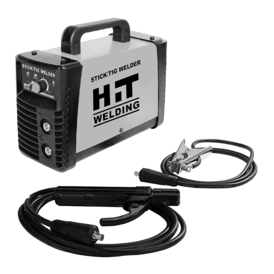
PSTICK80
Stick Welder with TIG Option
Assembly & Operating Instructions
READ ALL INSTRUCTIONS AND WARNINGS BEFORE USING THIS PRODUCT.
This manual provides important information on proper operation & maintenance. Every effort has been made to
ensure the accuracy of this manual. These instructions are not meant to cover every possible condition and situation
that may occur. We reserve the right to change this product at any time without prior notice.
IF THERE IS ANY QUESTION ABOUT A CONDITION BEING SAFE OR UNSAFE, DO NOT
OPERATE THIS PRODUCT!
HAVE QUESTIONS OR PROBLEMS? DO NOT RETURN THIS PRODUCT TO THE RETAILER -
CONTACT CUSTOMER SERVICE.
If you experience a problem or need parts for this product, visit our website http://www.buffalotools.com
or call our customer help line at 1-888-287-6981 Monday-Friday, 8 AM - 4 PM Central Time.
A copy of the sales receipt is required.
FOR CONSUMER USE ONLY – NOT FOR PROFESSIONAL USE.
KEEP THIS MANUAL, SALES RECEIPT & APPLICABLE WARRANTY FOR FUTURE REFERENCE.
C A L I F O R N I A P R O P O S I T I O N 6 5 W A R N I N G : T h i s p r o d u c t m a y c o n t a i n c h e m i c a l s , i n c l u d i n g
l e a d , k n o w n t o t h e S t a t e o f C a l i f o r n i a t o c a u s e c a n c e r a n d b i r t h d e f e c t s o r o t h e r r e p r o d u c t i v e
h a r m . W a s h h a n d s a f t e r h a n d l i n g .
PAGE 1
Advertisement
Table of Contents

Subscribe to Our Youtube Channel
Related Manuals for Buffalo Tools PSTICK80


Summary of Contents for Buffalo Tools PSTICK80
- Page 1 PSTICK80 Stick Welder with TIG Option Assembly & Operating Instructions READ ALL INSTRUCTIONS AND WARNINGS BEFORE USING THIS PRODUCT. This manual provides important information on proper operation & maintenance. Every effort has been made to ensure the accuracy of this manual. These instructions are not meant to cover every possible condition and situation that may occur.
-
Page 2: Technical Specifications
PSTICK80 FEATURES The Stick Welder is a DC only inverter stick welder with a smooth stick welding performance. It is intended for use for welding steel, stainless steel, cast iron and hard surfacing using electrodes from 1/16 inch to 3/32 inch. This unit can also perform lift start DC TIG welding on steel and stainless steel materials with the optional TIG Torch. -
Page 3: General Safety Rules
GENERAL SAFETY RULES SAVE T HESE I NSTRUCTIONS Read and understand all instructions. Failure to follow all instructions listed below may result in serious injury. Do n ot a llow p ersons t o o perate o r a ssemble t his S TICK W ELDER u ntil t hey h ave r ead t his manual ... - Page 4 Use o f Y our W elder Do not operate the welder if the output cable, electrode, torch, wire or wire feed system is wet. Do not immerse them in water. These components and the welder must be completely dry before use. - Follow the instructions in this manual.
- Page 5 Fumes and Gases -Fumes emitted from the welding process displace clean air and can result in injury or death. -Do not breathe in fumes emitted by the welding process. Make sure your breathing air is clean and safe. -Work only in a well-ventilated area or use a ventilation device to remove welding fumes from the environment where you will be working.
- Page 6 -Keep work lead connected as close to the weld area as possible to prevent any unknown, unintended paths of electrical current from causing electrical shock and fire hazards. -To prevent any unintended arcs, cut wire back to ¼" stick out after welding. ...
- Page 7 Shielding Gas Cylinders Can Explode High pressure cylinders can explode if damaged, so treat them carefully. -Never expose cylinders to high heat, sparks, open flames, mechanical shocks or arcs. -Do not touch cylinder with MIG gun. -Do not weld on the cylinder -Always secure cylinder upright to a cart or stationary object.
-
Page 8: Installation
Current A djustment Current adjustment is on the front panel of the machine. It has infinite current output adjustment from 20 to 75 Amps. Positive O utput C onnector This is the connector for the electrode holder and cable, most often, when STICK welding. When this machine is used for TIG welding, this connector is for the grounding cable. -
Page 9: Operation
3. INSTALLATION OF OPTIONAL TIG TORCH 3.1 Remove the ground cable and the electrode holder from the weld output connections. Install the ground cable to the Positive (+) weld output connection. 3.2 Secure the ground clamp to the work piece 3.3 Connect a regulator to a bottle of ARGON gas. - Page 10 4. SETTING UP THE WORK PIECE Connection between Welder and Power Supply. Connect the power supply cable at the back board of the welder into the single phase 120 voltage power network with breaker; (380 voltage power sources is strictly prohibited to the welder which will severely damage the welder) 4.1 Welding positions There are two basic positions, for welding: Flat and Horizontal.
-
Page 11: Ground Clamp Connection
Based on different welding position, there are different welding joint, see following image: 5. GROUND CLAMP CONNECTION Clear any dirt, rust, scale, oil or paint on the ground clamp. Make certain you have a good solid ground connection. A poor connection at the ground clamp will waste power and heat. Make sure the ground clamp touches the metal. -
Page 12: Welding Techniques
8. SETTING THE AMPERAGE CONTROL The welder has an infinite current control. It is capable of welding with electrodes up to 3/32” diameter. There is no golden rule that determines the exact amperage required for every situation. It is best to practice your welds on scrap metal which matches the metals you intend to work with to determine correct setting for your job. - Page 13 A good arc is accompanied by a crisp, cracking sound. The sound is similar to that made by eggs frying. To lay a weld bead, only 2 movements are required; downward (as the electrode is consumed) and in the direction the weld is to be laid, as in following figure: 9.3 Types of weld bead The following paragraphs discuss the most commonly used arc welding beads.
-
Page 14: Maintenance
Judge the good weld bead When the trick of establishing and holding an arc has been learned, the next step is learning how to run a good bead. The first attempts in practice will probably fall short of acceptable weld beads. Too long of an arc will be held or the travel speed will vary from slow to fast (see following) A. -
Page 15: Troubleshooting
TROUBLESHOOTING SYMPTOM POSSIBLE CAUSE CORRECTIVE ACTION Unit Does Not Power Up Unit Is Not Plugged In Plug In Unit Input Power Circuit Breaker Not On Reset Input Power Circuit Breaker The Main Power Switch Is Not Working Replace Main Power Switch Can Not Create An Arc Work Piece is Painted Or Rusty Remove All Paint And Rust... -
Page 16: Parts List
PARTS LIST Part Number Description Reference 2.05.08.031 Handle Black 155*42*27 1.1.01.01.1006 Encloser PSTICK160KE.2 1.1.05.02.0558 Main control board POWERSTICK 80KE (V1.3) 2.03.30.1235 STICK-TIG toggle switch BLUEARC 90 STI 2.03.30.1219 Potentiometer wiring harness POWER STICK 80KE (V1.0) 2.03.30.1217 Indicator light wiring harness POWER STICK 80KE (V1.0) 2.05.05.961 Front panel...
Need help?
Do you have a question about the PSTICK80 and is the answer not in the manual?
Questions and answers