DURKOPP ADLER 867 Durkopp Adler
Hide thumbs
Also See for 867:
- Service instructions manual (164 pages) ,
- Parts list (153 pages) ,
- Operating manual (120 pages)
Table of Contents
Advertisement
Quick Links
Advertisement
Table of Contents

Related Manuals for DURKOPP ADLER 867


Summary of Contents for DURKOPP ADLER 867
- Page 1 Operating Instructions...
- Page 2 IMPORTANT READ CAREFULLY BEFORE USE KEEP FOR FUTURE REFERENCE All rights reserved. Property of Dürkopp Adler AG and protected by copyright. Any reuse of these contents, including extracts, is prohibited without the prior written approval of Dürkopp Adler AG. Copyright © Dürkopp Adler AG 2018...
-
Page 3: Table Of Contents
Setting the sewing foot pressure ............54 4.13 Sewing foot stroke ................56 4.13.1 Limiting of number of stitches with an increased sewing foot stroke... 56 4.13.2 Setting the sewing foot stroke ............. 57 Operating Instructions 867 - 04.0 - 03/2018... - Page 4 Tabletop ....................99 7.4.1 Completing a short arm tabletop ............99 7.4.2 Completing a long arm tabletop ............101 Assembling the tabletop to the stand ..........102 Setting the working height ..............103 Operating Instructions 867 - 04.0 - 03/2018...
- Page 5 Errors in sewing process ..............147 Technical data ................. 149 11.1 Noise emission .................. 149 11.2 Data overview by subclassses ............149 11.3 Characteristics................... 162 11.4 Permissible maximum speeds............163 Appendix ..................171 Operating Instructions 867 - 04.0 - 03/2018...
- Page 6 Table of Contents Operating Instructions 867 - 04.0 - 03/2018...
-
Page 7: About These Instructions
Specifically, the chapter Setup ( p. 97) is important for specialists. Service Instructions are supplied separately. With regard to minimum qualification and other requirements to be met by personnel, please also follow the chapter Safety ( p. 9). Operating Instructions 867 - 04.0 - 03/2018... -
Page 8: Representation Conventions - Symbols And Characters
Lists are marked by bullet points. Result of performing an operation Change to the machine or on the display/control panel. Important Special attention must be paid to this point when performing a step. Operating Instructions 867 - 04.0 - 03/2018... -
Page 9: Other Documents
Each manufacturer has performed a hazard assessment for these purchased parts and confirmed their design compliance with applicable European and national regulations. The proper use of the built-in components is described in the corresponding manu- facturer's instructions. Operating Instructions 867 - 04.0 - 03/2018... -
Page 10: Liability
Leave machines, equipment and packaging material in the con- dition in which they were found when the damage was discovered. This will ensure any claims against the transport company. Report all other complaints to Dürkopp Adler immediately after receiving the product. Operating Instructions 867 - 04.0 - 03/2018... -
Page 11: Safety
The power plug may only be assembled to the power cable by qualified specialists. Obligations Follow the country-specific safety and accident prevention regu- of the operator lations and the legal regulations concerning industrial safety and the protection of the environment. Operating Instructions 867 - 04.0 - 03/2018... -
Page 12: Signal Words And Symbols Used In Warnings
Signal words Signal words and the hazard they describe: Signal word Meaning DANGER (with hazard symbol) If ignored, fatal or serious injury will result WARNING (with hazard symbol) If ignored, fatal or serious injury can result Operating Instructions 867 - 04.0 - 03/2018... - Page 13 If ignored, environmental damage can result NOTICE (without hazard symbol) If ignored, property damage can result Symbols The following symbols indicate the type of danger to personnel: Symbol Type of danger General Electric shock Puncture Crushing Environmental damage Operating Instructions 867 - 04.0 - 03/2018...
- Page 14 Type and source of danger! Consequences of non-compliance. Measures for avoiding the danger. This is what a warning looks like for a hazard that could result in moderate or minor injury if the warning is ignored. Operating Instructions 867 - 04.0 - 03/2018...
- Page 15 CAUTION Type and source of danger! Consequences of non-compliance. Measures for avoiding the danger. This is what a warning looks like for a hazard that could result in environmental damage if ignored. Operating Instructions 867 - 04.0 - 03/2018...
- Page 16 Safety Operating Instructions 867 - 04.0 - 03/2018...
-
Page 17: Machine Description
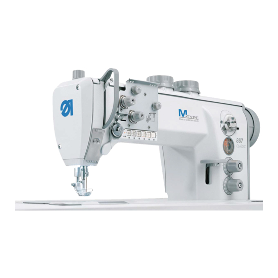
(2) - Tensioning plate (8) - Oil level indicator (3) - Adjusting wheel for (9) - Handwheel the sewing foot pressure (10) - Reel stand (4) - Push buttons on the machine arm (5) - Winder Operating Instructions 867 - 04.0 - 03/2018... -
Page 18: Proper Use
DIN EN 60204-31. Only authorized persons may work on the machine. Dürkopp Adler cannot be held liable for damages resulting from improper use. Operating Instructions 867 - 04.0 - 03/2018... -
Page 19: Declaration Of Conformity
Machine description Declaration of Conformity The machine complies with European regulations ensuring health, safety, and environmental protection as specified in the declara- tion of conformity or in the declaration of incorporation. Operating Instructions 867 - 04.0 - 03/2018... - Page 20 Machine description Operating Instructions 867 - 04.0 - 03/2018...
-
Page 21: Operation
• Inserting/changing the needle ( p. 21) • Threading the needle thread ( p. 27). • Inserting and winding on the hook thread ( p. 38) • Setting the thread tension ( p. 43) Operating Instructions 867 - 04.0 - 03/2018... -
Page 22: Switching On And Off The Machine
Switching off the machine To switch off the machine: Set the main switch (2) to position 0. The power supply is switched off, and the indicator lamps (1) and (3) are no longer lit. Operating Instructions 867 - 04.0 - 03/2018... -
Page 23: Inserting/Changing The Needle
Check the distance to the hook tip after inserting a needle with a different thickness. Set the distance again if necessary. Order After switching to a different needle thickness, adjust the distance between hook and needle ( Service Instructions). Operating Instructions 867 - 04.0 - 03/2018... -
Page 24: In 1-Needle Machines
To insert or change the needle on 1-needle machines: Turn the handwheel until the needle bar (1) reaches the upper end position. Loosen the screw (2). Pull the needle out towards the bottom. Insert the new needle. Operating Instructions 867 - 04.0 - 03/2018... -
Page 25: In 2-Needle Machines
When inserting the needles, align them such that the grooves (3) face away from each other. Each groove (3) must point to the hook (4) that belongs to this needle. Tighten the screws (2) on both sides. Operating Instructions 867 - 04.0 - 03/2018... -
Page 26: Machines With Switchable Needle Bars
When inserting the needles, align them such that the grooves (3) face away from each other. Each groove must point to the hook that belongs to this needle. Tighten the screws (2) on both sides. Operating Instructions 867 - 04.0 - 03/2018... -
Page 27: Feeding Needle/Hook Thread
(3) - Thread reel holder (2) - Plate To feed the needle/hook thread: Fit the thread reel on the plate (2). The unwinding bracket (1) must stand directly above the thread reel holder (3). Operating Instructions 867 - 04.0 - 03/2018... - Page 28 Insert the needle thread ( p. 27 or p. 32). You can now thread needle and hook thread ( p. 27 and p. 41) and set the thread tension ( p. 43). Operating Instructions 867 - 04.0 - 03/2018...
-
Page 29: Threading The Needle Thread
(1) - Thread guide (6) - Main tensioner (2) - Spring tip (7) - Additional tensioner (3) - Tightening lever (8) - Pre-tensioner (4) - Thread tension spring (9) - Thread guide (5) - Thread guide Operating Instructions 867 - 04.0 - 03/2018... - Page 30 Feed the needle thread through the thread guide (5) to the thread tension spring (4). Lift the tightening lever (3) with the needle thread. Pull the needle thread under the spring tip (2). Operating Instructions 867 - 04.0 - 03/2018...
- Page 31 (14). 11. Insert the needle thread from the right to the left through the thread lever (15). 12. Insert the needle thread through the upper thread guide (11). Operating Instructions 867 - 04.0 - 03/2018...
- Page 32 (16). 16. Insert the needle thread through the thread guide on the nee- dle bar (13). Operating Instructions 867 - 04.0 - 03/2018...
- Page 33 If the loose thread end is too long, the needle thread may be caught by the hook and cause a disturbance. If the loose thread end is too short, the machine cannot start sewing. Operating Instructions 867 - 04.0 - 03/2018...
-
Page 34: In 2-Needle Machines
(6). Guide the right needle thread counterclockwise around the additional tensioner (5). Guide the right needle thread clockwise around the main tensioner (4). Guide the left needle thread clockwise around the pre-tensioner (1). Operating Instructions 867 - 04.0 - 03/2018... - Page 35 (13). 12. Thread the right needle thread from the right through the lower hole on the thread lever (15). 13. Guide the left needle thread to the rear thread tension spring (11). Operating Instructions 867 - 04.0 - 03/2018...
- Page 36 (see figure Page 30). 26. Insert the right needle thread through the right thread guide of the needle bar. 27. Insert the left needle thread through the left thread guide of the needle bar. Operating Instructions 867 - 04.0 - 03/2018...
- Page 37 If the loose thread end is too long, the needle thread may be caught by the hook and cause a disturbance. If the loose thread end is too short, the machine cannot start sewing. Operating Instructions 867 - 04.0 - 03/2018...
-
Page 38: Machines With A Neat Seam Beginning
3 holes of the thread guide (1): From top to bottom through the left hole, then from bottom to top through the middle hole and, finally, from top to bottom through the right hole. Operating Instructions 867 - 04.0 - 03/2018... - Page 39 14. Feed the needle thread through the thread guide on the needle bar. 15. Insert the needle thread through the needle eye in such a way that the loose thread end faces the hook. Operating Instructions 867 - 04.0 - 03/2018...
-
Page 40: Winding The Hook Thread
However, you can also wind on the hook thread without sewing, e. g. if you require a full bobbin in order to start sewing. To wind the hook thread: Feed the hook thread properly ( p. 25). Operating Instructions 867 - 04.0 - 03/2018... - Page 41 Fig. 14: Winding the hook thread (3) ⑦ ⑤ ⑥ (5) - Winder lever (7) - Cutter (6) - Bobbin shaft Clamp the hook thread behind the cutter (7) and tear off the loose end behind it. Operating Instructions 867 - 04.0 - 03/2018...
- Page 42 12. Remove the full bobbin from the bobbin shaft (6). 13. Tear off the thread behind the cutter (7). You can now insert the full bobbin into the hook ( p. 41). Operating Instructions 867 - 04.0 - 03/2018...
-
Page 43: Changing The Bobbin
Fig. 16: Changing the bobbin (2) ⑧ ③ ④ ⑤ ⑥ ⑦ (3) - Slot (6) - Slot (4) - Guide (7) - Bobbin (5) - Tension spring (8) - Bobbin case retainer Operating Instructions 867 - 04.0 - 03/2018... - Page 44 Feed the hook thread through the slot (6) in the bobbin case retainer. Pull the hook thread under the tension spring (5). Feed the hook thread through the slot (3) and pull it approx. 3 cm further. Close the bobbin case retainer (8). Operating Instructions 867 - 04.0 - 03/2018...
-
Page 45: Thread Tension
Fig. 18: Thread tension ① ② ③ (1) - Identical needle thread and hook thread tension (2) - Hook thread tension higher than needle thread tension (3) - Needle thread tension higher than hook thread tension Operating Instructions 867 - 04.0 - 03/2018... -
Page 46: Setting The Needle Thread Tension
(1) - Main tensioner (3) - Pre-tensioner (2) - Additional tensioner To increase the needle thread tension: Turn the adjusting wheel clockwise. To reduce the needle thread tension: Turn the adjusting wheel counterclockwise. Operating Instructions 867 - 04.0 - 03/2018... - Page 47 On CLASSIC machines with a push button panel on the machine arm, the additional tensioner is switched on and off via the corre- sponding function button on the push button panel ( p. 65). Operating Instructions 867 - 04.0 - 03/2018...
- Page 48 The main tensioner should be set as low as possible. The thread interlacing should be exactly in the middle of the sewing material. Faults due to excessively high tension • Ruffing • Thread breaking Operating Instructions 867 - 04.0 - 03/2018...
-
Page 49: Removing Blocking Of The Needle Thread Tension
The needle thread tension is automatically opened when the sewing feet are lifted via the knee lever ( p. 51). • CLASSIC machines When the thread is cut, the needle thread tension is opened automatically ( p. 52). Operating Instructions 867 - 04.0 - 03/2018... -
Page 50: Setting The Hook Thread Tension
The hook thread tension is adjusted using the adjusting screw (1). To increase the hook thread tension: Turn the adjusting screw (1) clockwise. To reduce the hook thread tension: Turn the adjusting screw (1) counterclockwise Operating Instructions 867 - 04.0 - 03/2018... -
Page 51: Setting The Needle Thread Regulator
Loosen the screw (1). • To increase the tension: Slide the needle thread regulator (2) to the right • To reduce the tension: Slide the needle thread regulator (2) to the left Tighten the screw (1). Operating Instructions 867 - 04.0 - 03/2018... -
Page 52: In 2-Needle Machines
Loosen the screw (3). • To increase the tension: Slide the needle thread regulator (4) to the right. • To reduce the tension: Slide the needle thread regulator (4) to the left. Tighten the screw (3). Operating Instructions 867 - 04.0 - 03/2018... -
Page 53: Lifting The Sewing Feet
• ECO machines: mechanically using the knee lever • CLASSIC machines: electropneumatically using the pedal 4.10.1 Mechanical lifting with the knee lever Fig. 25: Mechanical lifting with the knee lever ① (1) - Knee lever Operating Instructions 867 - 04.0 - 03/2018... -
Page 54: Electropneumatic Lifting With The Pedal
The machine stops and lifts the sewing feet. The sewing feet remain up as long as the pedal is pressed halfway back. Press the pedal (1) fully back. The thread cutter is activated, and the sewing feet are raised. Operating Instructions 867 - 04.0 - 03/2018... - Page 55 To lock the sewing feet at top dead center: Swivel the lever (1) down. The sewing feet are locked at top dead center. Swivel the lever (1) up. Top dead center is canceled. Operating Instructions 867 - 04.0 - 03/2018...
-
Page 56: Setting The Sewing Foot Pressure
Removing blocking of the adjusting wheel Machines with blockable adjusting wheels are used especially in the automotive sector. With these machines the blocking must be removed before the sewing foot pressure can be adjusted. Operating Instructions 867 - 04.0 - 03/2018... - Page 57 • To increase the sewing foot pressure: Turn the adjusting wheel (3) clockwise • To reduce the sewing foot pressure: Turn the adjusting wheel (3) counterclockwise Tighten the blocking element (1) using the screw (2). Operating Instructions 867 - 04.0 - 03/2018...
-
Page 58: Sewing Foot Stroke
ECO machines do not have automatic reduction of the number of stitches. On ECO machines, you as the user must ensure that the number of stitches specified in the technical data is not exceeded ( p. 163). Operating Instructions 867 - 04.0 - 03/2018... -
Page 59: Setting The Sewing Foot Stroke
(2) sets the increased sewing foot stroke. The increased sewing foot stroke can be switched on and off using the button on the push button panel or the knee button ( p. 59). Operating Instructions 867 - 04.0 - 03/2018... - Page 60 • Adjusting wheel (2): increased sewing foot stroke (switchable stroke) To set the sewing foot stroke: Increasing the sewing foot stroke Turn the adjusting wheel clockwise. Reducing the sewing foot stroke Turn the adjusting wheel counterclockwise. Operating Instructions 867 - 04.0 - 03/2018...
-
Page 61: Quick Stroke Adjustment Via Knee Button
Press the knee button once. To deactivate the sewing foot stroke: Press the knee button one more time. Hold-to-run The sewing foot stroke remains activated mode for as long as you hold down the knee button. Operating Instructions 867 - 04.0 - 03/2018... -
Page 62: Removing Blocking Of The Sewing Foot Stroke Adjusting Wheels
To remove the blocking of the adjusting wheels for the sewing foot stroke: Loosen the blocking screws (1). Turn the adjusting wheels for the sewing foot stroke (2) ( p. 56). Tighten the blocking screws (1). Operating Instructions 867 - 04.0 - 03/2018... -
Page 63: Stitch Length
Setting the stitch length on the adjusting wheel (4) Turn the adjusting wheel (4) clockwise until you reach the desired stitch length. The marking (2) on the left of the adjusting wheel indicates the stitch length selected. Operating Instructions 867 - 04.0 - 03/2018... -
Page 64: Sewing With 2 Stitch Lengths
These can be used to sew two different stitch lengths and can be activated with a press of button (1). The stitch lengths are set using the adjusting wheels (3) and (4). Operating Instructions 867 - 04.0 - 03/2018... -
Page 65: Removing Blocking Of The Adjusting Wheels
Turn the stitch length adjusting wheels (1) ( p. 61). Insert a 3 mm hex key through the access holes (2) and tighten the blocking screws for the stitch length adjusting wheels. Operating Instructions 867 - 04.0 - 03/2018... -
Page 66: Push Buttons On The Machine Arm
If start/ end bartacks are off, pressing the button (3) sews the next bartack. For the general setting required for sewing start and end bartacks, refer to the Instructions for use for the DAC classic control. Operating Instructions 867 - 04.0 - 03/2018... -
Page 67: Switching On And Off The Function Of A Button
The button lights up; the function is switched on. To switch the function of a button off: Press the button (1)/(2)/(3)/(4)/(5)/(6) whose function is switched on. The button is no longer lit; the function is switched off. Operating Instructions 867 - 04.0 - 03/2018... -
Page 68: Assigning Functions To The Favorite Button
Only one function at a time can be assigned to the favorite button (1). Only one of the screws (2) may be in the vertical position. All screws must be turned back to their horizontal initial position before a new function is assigned. Operating Instructions 867 - 04.0 - 03/2018... -
Page 69: Switching The Binder
The binder follows a shorter path. When the machine is switched on, the binder always follows the same path as the feed dog - regardless of which button was pressed before the machine was switched off. Operating Instructions 867 - 04.0 - 03/2018... - Page 70 The binder follows the same path as the feed dog. Information You cannot directly switch between plus and minus. Deactivate the respectively illuminated button as described in step 2 before switching to the other button. Operating Instructions 867 - 04.0 - 03/2018...
-
Page 71: Switching Needle Bars On/Off
You cannot switch off both needle bars at the same time. When a needle bar is switched off and you press the button for the other needle bar, this switches on the disabled needle bar so that both needle bars are in use. Operating Instructions 867 - 04.0 - 03/2018... -
Page 72: Switching On And Off The Sewing Lamp
Use the - (1) or + (3) button to set the brightness level. To switch off the sewing lamp: Press the button (2). The sewing lamp goes out. Set the switch (4) to position 0. Operating Instructions 867 - 04.0 - 03/2018... -
Page 73: Operating The Control
See accessory pack included with the control • Control DAC eco and DAC basic/classic: See accessory pack included with the control The instructions for use are also available in the download area at www.duerkopp-adler.com Operating Instructions 867 - 04.0 - 03/2018... -
Page 74: Sewing
(1) - Pedal position -2 (3) - Pedal position 0 (Sew end bartack and (Rest position) cut off thread) (4) - Pedal position +1 (2) - Pedal position -1 (Sew forward) (Lift the sewing feet) Operating Instructions 867 - 04.0 - 03/2018... - Page 75 The 2 stitch length must be switched on using the quick function button ( p. 62). Increasing the thread tension Switch on the additional tensioner using the quick function button ( p. 64). Operating Instructions 867 - 04.0 - 03/2018...
-
Page 76: Sewing Backwards
Slowly push the stitch adjustment lever (1) down. The stitch length becomes smaller. In the lower end position, the machine sews in reverse with the stitch length currently set at the adjusting wheels. Operating Instructions 867 - 04.0 - 03/2018... - Page 77 Operation Information Another option for turning on sewing in reverse is to use the button for reverse sewing on the machine arm. Operating Instructions 867 - 04.0 - 03/2018...
- Page 78 Operation Operating Instructions 867 - 04.0 - 03/2018...
-
Page 79: Programming
All software settings are performed using the OP1000 control panel. The control panel is composed of a display and buttons. Using the control panel you can: • Use groups of buttons to select machine functions • Read service and error messages Operating Instructions 867 - 04.0 - 03/2018... -
Page 80: Buttons On The Op1000 Control Panel
(1) - Power LED (5) - Seam program button group (2) - Thread button group (6) - LED for 2nd Stitch length (3) - Function button (7) - Display (4) - Programming button group Operating Instructions 867 - 04.0 - 03/2018... - Page 81 Needle position after • Sets the needle position sewing stop after sewing stop Sewing foot lift after • Activates or deactivates thread cutter the sewing foot lift after the thread cutter Operating Instructions 867 - 04.0 - 03/2018...
- Page 82 • Increases parameter • Changes user level • Selects subprogram • Increases parameter • Changes to next higher category • Selects subprogram • Increases parameter • Selects subprogram • Increases parameter • Selects subprogram Operating Instructions 867 - 04.0 - 03/2018...
- Page 83 • Selects subprogram • Decreases parameter • Changes to next lower category • Selects subprogram • Decreases parameter • Selects subprogram • Decreases parameter • Selects subprogram Reset • Resets the (piece) counter Operating Instructions 867 - 04.0 - 03/2018...
-
Page 84: Assigning Functions To Buttons On The Push Button Panel
The buttons on the push button panel can be assigned different functions. Possible function assignments are: • Suppress start/end bartack • Start/end bartack • Single stitch • Needle up/down • Edge cutting • Stroke adjustment Operating Instructions 867 - 04.0 - 03/2018... -
Page 85: Assigning A Function To The Knee Button
The control panel shows the value currently set for the button. Use +/- to enter the desired value; see Parameter list 867, parameter t 51 20 for information on which function is assigned which value. -
Page 86: Control Panel V810
The display shows a numerical value (parameter t 5120). Use the buttons + or - to set the numerical value to the desired value associated with the new function ( Parameter list 867). Confirm with Control panel V810 Follow the Operating Instructions of the manufacturer. -
Page 87: Maintenance
( Service Instructions). Maintenance intervals Work to be carried out Operating hours Cleaning Removing lint and thread remnants Cleaning the motor fan mesh Lubricating Lubricating the machine head Lubricating the hook Operating Instructions 867 - 04.0 - 03/2018... -
Page 88: Cleaning The Machine
Property damage from soiling! Lint and thread remnants can impair the operation of the machine. Clean the machine as described. When sewing very fluffy material, clean the machine at shorted intervals than every 8 hours. Operating Instructions 867 - 04.0 - 03/2018... - Page 89 • Hook (3) • Area around the needle (2) To clean the machine: Switch off the machine ( p. 20). Remove any lint and thread remnants using a compressed air gun or a brush. Operating Instructions 867 - 04.0 - 03/2018...
-
Page 90: Cleaning The Motor Fan Mesh
Clean the motor fan mesh as described. When sewing very fluffy material, clean the machine at shorted intervals than every 160 hours. Fig. 47: Cleaning the motor fan mesh ① ② (1) - Tabletop (2) - Motor fan mesh Operating Instructions 867 - 04.0 - 03/2018... -
Page 91: Lubricating
Carefully collect up used oil. Dispose of used oil and oily machine parts in accordance with national regulations. The machine is equipped with a central oil-wick lubrication system. The bearings are supplied from the oil reservoir. Operating Instructions 867 - 04.0 - 03/2018... -
Page 92: Lubricating The Machine Head
(2) - Minimum level marking To lubricate the machine head: Check the oil level indicator at the inspection glass every day. If the inspection glass lights up red, the machine is not suffi- ciently supplied with oil. Operating Instructions 867 - 04.0 - 03/2018... -
Page 93: Setting The Hook Lubrication
Allow the machine to run without thread and sewing material for 10 seconds with the sewing feet lifted and at a high speed. The blotting paper will show a thin strip of oil when sewing is complete. Operating Instructions 867 - 04.0 - 03/2018... -
Page 94: Servicing The Pneumatic System
Refer to the Technical data ( p. 149) chapter for the permissi- ble operating pressure. The operating pressure cannot deviate by more than ± 0.5 bar. Check the operating pressure on a daily basis. Operating Instructions 867 - 04.0 - 03/2018... - Page 95 Pull the pressure controller (1) up. Turn the pressure controller until the pressure gage (2) indicates the proper setting: • Increase pressure = turn clockwise • Reduce pressure = turn counterclockwise Push the pressure controller (1) down. Operating Instructions 867 - 04.0 - 03/2018...
-
Page 96: Draining The Water Condensation
To drain water condensation: Disconnect the machine from the compressed air supply. Place the collection tray under the drain screw (3). Loosen the drain screw (3) completely. Allow water to drain into the collection tray. Operating Instructions 867 - 04.0 - 03/2018... -
Page 97: Cleaning The Filter Element
Drain the water condensation ( p. 94). Loosen the water separator (2). Loosen the filter element (1). Blow out the filter element (1) using a compressed air gun. Wash out the filter tray using benzine. Operating Instructions 867 - 04.0 - 03/2018... -
Page 98: Parts List
Tighten the drain screw (3). 10. Connect the machine to the compressed air supply. Parts list A parts list can be ordered from Dürkopp Adler. Or visit our website for further information at: www.duerkopp-adler.com Operating Instructions 867 - 04.0 - 03/2018... -
Page 99: Setup
All transport locks must be removed prior to setup: • All lashing straps and wooden blocks from the machine head, the table and the stand • Supporting wedges between machine arm and throat plate Operating Instructions 867 - 04.0 - 03/2018... -
Page 100: Assembling The Stand
Important: Turn the adjusting screw (4) so that the stand has even contact with the ground. Information Stand components for long arm machines have 2 cross bars, while the other stand components have 1 cross bar. Operating Instructions 867 - 04.0 - 03/2018... -
Page 101: Tabletop
④ (1) - Machine head support (4) - Oil pan (2) - Slot for the (5) - Cable duct Lower hinge part (6) - Corner slot (3) - Drawer (7) - Reel stand Operating Instructions 867 - 04.0 - 03/2018... - Page 102 (7) in such a way that they are exactly opposite each other. Insert the machine head support (1) into the hole. Insert and fasten the lower hinge parts in the hinge slots (2). Insert the rubber corners into the corner slots (6). Operating Instructions 867 - 04.0 - 03/2018...
-
Page 103: Completing A Long Arm Tabletop
(7) in such a way that they are exactly opposite each other. Insert the plug (6) in the hole. Insert the lower hinge parts into the slots (2). Insert the rubber corners into the corner slots (5). Operating Instructions 867 - 04.0 - 03/2018... -
Page 104: Assembling The Tabletop To The Stand
(2) - Screws To assemble the tabletop to the stand: Place the tabletop on the head sections of the inner bars. Use the screws (2) to fasten the tabletop at the screw holes (1). Operating Instructions 867 - 04.0 - 03/2018... -
Page 105: Setting The Working Height
900 mm (clearance between the floor and upper edge of the tabletop). Fig. 56: Setting the working height ① (1) - Screw To set the working height: Loosen the screws (1) on the stand bars. Set the tabletop to the desired height. Operating Instructions 867 - 04.0 - 03/2018... -
Page 106: Assembling The Control
Machines with 190142-M DAC classic integrated motor 190322-M 190342-M Short arm 392342 Efka DC 1550/ 393342 DA 321G 394342 190122 190142 160122 260122 190145 190125 190146 190322 190342 190445 190425 29040 29020 290122 290142 Operating Instructions 867 - 04.0 - 03/2018... -
Page 107: Assembling The Control
Screw the control (2) onto the 4 screw holders (3) under the tabletop. Clamp the power cable of the control (2) into the strain relief mechanism (1). Screw the strain relief mechanism (1) under the tabletop. Operating Instructions 867 - 04.0 - 03/2018... -
Page 108: Assembling The Pedal And Setpoint Device
Attach the pedal rod (1) with the ball sockets to the setpoint device (5) and to the pedal (4). Slightly loosen the screw (2). Pull the pedal rod (1) to the correct length: Proper setting: 10° inclination with pedal (4) released Operating Instructions 867 - 04.0 - 03/2018... -
Page 109: Inserting The Machine Head
Insert the machine head from above at an angle of 45°. Insert the hinges (2) into the hinge slots (1). Fold down the machine head and insert it fully into the tabletop cutout. Operating Instructions 867 - 04.0 - 03/2018... -
Page 110: Assembling The Control Panel
(3) - Cable duct (only for long arm; not visible here) To assemble the control panel: Unscrew the machine cover (1) and the valve cover (2). Tighten the control panel (5) on the control panel bracket (4). Operating Instructions 867 - 04.0 - 03/2018... - Page 111 Feed the connecting cable (6) along with the remaining cables through the hole in the tabletop. Insert the plug of the connecting cable (6) into the socket of the control. Screw on the valve cover (2) and the upper machine cover (1). Operating Instructions 867 - 04.0 - 03/2018...
-
Page 112: Assembling The Knee Lever / Knee Button
③ (1) - Oil pan (3) - Knee lever (2) - Rod (4) - Connecting piece Fig. 63: Assembling the mechanical knee lever (2) ⑤ ⑥ (5) - Transmission rod (6) - Screw Operating Instructions 867 - 04.0 - 03/2018... -
Page 113: Assembling The Electric Knee Button
Guide the connecting cable (2) to the back between the oil pan and the control. Insert the plug (3) of the connecting cable (2) into the socket of the control ( p. 122). Operating Instructions 867 - 04.0 - 03/2018... -
Page 114: Assembling The Oil Extraction Line
To assemble the oil extraction line: Tilt the machine head. Tighten the filter (2) inside the oil pan with the plastic adapter to the right. Insert the tube of the oil extraction line (1) into the plastic adapter. Operating Instructions 867 - 04.0 - 03/2018... -
Page 115: Electrical Connection
7.12.1 Checking the mains voltage Important The voltage on the type plate of the sewing motor must correspond to the mains voltage. 1. Check the mains voltage before connecting the machine. Operating Instructions 867 - 04.0 - 03/2018... -
Page 116: Assembling And Connecting The Sewing Lamp And Sewing Lamp Transformer
Unscrew the valve cover and upper machine cover ( p. 108). The upper machine cover has pre-drilled holes for attaching the sewing lamp. Fig. 66: Assembling the sewing lamp ② ① (1) - Large hole (2) - Small holes Operating Instructions 867 - 04.0 - 03/2018... - Page 117 Screw the sewing lamp transformer (1) in place at the pre-drilled holes (2) under the tabletop. Assemble the connecting cable under the tabletop using cable ties. Establish the plug connection to the supply line for the sewing lamp. Operating Instructions 867 - 04.0 - 03/2018...
- Page 118 Loosen the adapter cover screws (2). Connect the supply line: • For sewing lamps to be additionally assembled to the X3 connection (4) • For integrated LED sewing lamps on the 24V/X5 connection (3) Operating Instructions 867 - 04.0 - 03/2018...
- Page 119 Insert the black rubber guide (2) again. Press a narrow screwdriver into the terminal openings (5) to open terminals (3) and (4). Important: Do not press so hard that the board is pressed in. Operating Instructions 867 - 04.0 - 03/2018...
-
Page 120: Establishing Equipotential Bonding
Feed the protective earth conductor from the connection (1) on the rear side Feed the control through the cutout in the tabletop and slip it onto the tab connector (2) on the base plate. Operating Instructions 867 - 04.0 - 03/2018... -
Page 121: Connecting The Control
See accessory pack included with the control. • DAC eco and DAC classic controls: See accessory pack included with the control. The instructions also available in the download area at www.duerkopp-adler.com Fig. 71: Connecting the control Operating Instructions 867 - 04.0 - 03/2018... -
Page 122: Connecting The Machine Head
For this reason, when using the Hall sensor it is important to ensure that the maximum speed for the respective subclass is not exceeded. To assemble the Hall sensor: Remove the handwheel and handwheel cover. Remove the valve cover. Operating Instructions 867 - 04.0 - 03/2018... - Page 123 1000 Machine belt pulley diameter (teeth) With DAC controls the parameters are automatically set via transfer of the machine ID. Place the valve cover and tighten. Check the setting of the Hall sensor: Operating Instructions 867 - 04.0 - 03/2018...
-
Page 124: Connecting The Electric Knee Button
Insert the plug of the knee button into the socket of the respec- tive control: • DAC eco/classic control: Socket (2) on the rear side of the control • Efka DC1550/DA321G control: Socket KN19 (3) on the front side of the control Operating Instructions 867 - 04.0 - 03/2018... -
Page 125: Assembling And Connecting The M-Control Circuit Board
Circuit board for machines with binder: assemble between stand (1) and cable duct (2) Circuit board for machines with switchable needle bars: Assemble at the right next to the setpoint device angle bracket (3). Operating Instructions 867 - 04.0 - 03/2018... - Page 126 If the function of the R and L buttons are swapped over on machines with switchable needle bars, then the upper section compressed air hoses (1) are swapped on the throttle valves (4). Plug the electrical cable connectors into the connection sockets (3). Operating Instructions 867 - 04.0 - 03/2018...
-
Page 127: Setting Machine-Specific Parameters
The parameter sheet is provided in the control accessory pack. To set the machine-specific parameters: Set parameter F-290 according to the specifications in Parameter sheet. For subclass 867-290342-100 only: Set parameter F-111 to 2500 min or less. Operating Instructions 867 - 04.0 - 03/2018... -
Page 128: Pneumatic Connection
The pneumatic system of the machine and of the additional equipment must be supplied with dry and oil-free compressed air. The supply pressure must lie between 8 and 10 bar. Operating Instructions 867 - 04.0 - 03/2018... -
Page 129: Assembling The Compressed Air Maintenance Unit
The system pressure for the pneumatic unit is 8 – 10 bar. Fig. 77: Assembling the compressed air maintenance unit ④ ③ ① ② (1) - Cross bar (3) - Maintenance unit (2) - System connection hose (4) - Machine hose Operating Instructions 867 - 04.0 - 03/2018... -
Page 130: Setting The Operating Pressure
Ensure that the machine is only used when the operating pressure is set correctly. Proper setting Refer to the Technical data ( p. 149) chapter for the permissi- ble operating pressure. The operating pressure cannot deviate by more than ± 0.5 bar. Operating Instructions 867 - 04.0 - 03/2018... -
Page 131: Pneumatic Sewing Foot Lift
• Reduce pressure = turn counterclockwise Push the pressure controller (1) down. 7.13.3 Pneumatic sewing foot lift For information on how to assemble the pneumatic sewing foot lift, refer to the Additional Instructions 0791 867704. Operating Instructions 867 - 04.0 - 03/2018... -
Page 132: Lubricating
Pour oil through the refill opening (1) up to no more than 2 mm below the maximum level marking (3). The oil level must be above the minimum level marking (2) and just below the maximum level marking (3). Operating Instructions 867 - 04.0 - 03/2018... - Page 133 Only use oil specified in the operating instructions. Only DA 10 or equivalent oil should be used for the machine, which has the following properties: • Viscosity at 40 °C: 10 mm²/s • Flash point: 150 °C Operating Instructions 867 - 04.0 - 03/2018...
-
Page 134: Performing A Test Run
10. Set stitch length ( p. 61). 11. Assign a function to the favorite button ( p. 66). 12. Start the sewing test at low speed. 13. Gradually increase the speed until the working speed is reached. Operating Instructions 867 - 04.0 - 03/2018... -
Page 135: Decommissioning
Remove residual oil from the oil pan using a cloth. Cover the control panel to protect it from soiling. Cover the control to protect it from soiling. Cover the entire machine if possible to protect it from contam- ination and damage. Operating Instructions 867 - 04.0 - 03/2018... - Page 136 Decommissioning Operating Instructions 867 - 04.0 - 03/2018...
-
Page 137: Disposal
When disposing of the machine, be aware that it consists of a range of different materials (steel, plastic, electronic components, etc.). Follow the national regulations when disposing these materials. Operating Instructions 867 - 04.0 - 03/2018... - Page 138 Disposal Operating Instructions 867 - 04.0 - 03/2018...
-
Page 139: Troubleshooting
Contact for repairs and issues with the machine: Dürkopp Adler AG Potsdamer Str. 190 33719 Bielefeld, Germany Tel. +49 (0) 180 5 383 756 Fax +49 (0) 521 925 2594 Email: service@duerkopp-adler.com Internet: www.duerkopp-adler.com Operating Instructions 867 - 04.0 - 03/2018... -
Page 140: Messages Of The Software
• Connect encoder cable to plug (Sub-D, 9-pin) not the control, use correct connected connection 2122 DA stepper card 1 flywheel • Check connection cables position not found • Check stepper motor 1 for stiff movement Operating Instructions 867 - 04.0 - 03/2018... - Page 141 3217 Remaining thread monitor • Change the right bobbin right 3218 Remaining thread monitor left • Change the left and right and right bobbin 3223 Skip stitch detected 3224 Bobbin failed to rotate Operating Instructions 867 - 04.0 - 03/2018...
- Page 142 Internal EEprom defective • Replace the control and external data not valid (emergency operating features only) 6367 Internal EEprom defective • Replace the control and external EEprom not connected (emergency operating features only) Operating Instructions 867 - 04.0 - 03/2018...
- Page 143 DAC basic will remain available) 7803 Communication error • Restart of the control (DAC classic only; only the • Software update functions of the DAC basic • Replace the control will remain available) Operating Instructions 867 - 04.0 - 03/2018...
-
Page 144: Error Messages
• Eliminate stiff movement in the sewing machine • Replace the encoder • Replace sewing motor 1006 Error Maximum speed • Replace the encoder exceeded • Perform reset • Check class (t 51 04) Operating Instructions 867 - 04.0 - 03/2018... - Page 145 • Replace the control 1054 Error Internal short circuit • Replace the control 1055 Error Sewing motor overload • Eliminate stiff movement in the sewing machine • Replace the encoder • Replace sewing motor Operating Instructions 867 - 04.0 - 03/2018...
- Page 146 < 150 V AC • Stabilize the mains voltage • Use generator 3104 Warning Pedal is not in position 0 • When switching the control on, take your foot off the pedal Operating Instructions 867 - 04.0 - 03/2018...
- Page 147 • Switch off the control communication error • Wait until the LEDs are • Check machine ID connection • Switch the control back 8401 Error Watchdog • Software update • Machine ID reset • Replace the control Operating Instructions 867 - 04.0 - 03/2018...
- Page 148 8405 • Machine ID reset • Replace the control 8406 Error Checksum error • Software update • Replace the control 8501 Error Software protection • Always use the DA tool for software updates Operating Instructions 867 - 04.0 - 03/2018...
-
Page 149: Errors In Sewing Process
Check threading path p. 27 as thread tube, thread guide or thread take-up disk, are sharp-edged Throat plate, hook or Have parts reworked by spread have been qualified specialists damaged by the needle Operating Instructions 867 - 04.0 - 03/2018... - Page 150 p. 25 and p. 27 thread have not been threaded correctly Needle Needle thickness is Use recommended needle thickness p. 149 breakage unsuitable for the sewing material or the thread Operating Instructions 867 - 04.0 - 03/2018...
-
Page 151: Technical Data
120/3- 80/3-10/3 30/3 (up to 15/3 with short thread cutter) Stitch length, forwards / 12/12 backwards [mm] Number of adjustable stitch lengths Maximum s.p.m. 3800 Number of stitches on delivery 3400 3000 3400 Operating Instructions 867 - 04.0 - 03/2018... - Page 152 Rated power [kVA] 0.75 1-needle machines with extra-large hook (XXL) Subclasses: 867- Type of stitches Double lockstitch 301 Hook type Vertical hook, extra-large (XXL) Number of needles Needle system 134-35 Maximum needle strength [Nm] Operating Instructions 867 - 04.0 - 03/2018...
- Page 153 Maximum sewing foot stroke Positive operating pressure [bar] Air consumption [NL] Length/width/height [mm] 690/220/460 690/320/460 Weight/with direct drive [kg] 55/59 Rated voltage [V, Hz] 230, 50/60 Rated power [kVA] 0.75 Operating Instructions 867 - 04.0 - 03/2018...
- Page 154 3500 3200 3500 3200** 3000 Number of stitches on delivery 3400 3000 Maximum fan height (*only with reversing mechanism) Maximum sewing foot stroke Positive operating pressure [bar] Air consumption [NL] Length/width/height [mm] 690/220/460 Operating Instructions 867 - 04.0 - 03/2018...
- Page 155 Vertical hook, extra-large (XXL) Number of needles Needle system 134-35 Maximum needle strength [Nm] Maximum sewing thread 80/3-10/3 thickness Stitch length 12/12 Forwards/backwards [mm] Number of adjustable stitch lengths Maximum s.p.m. 3000 2500 Operating Instructions 867 - 04.0 - 03/2018...
-
Page 156: Weight/With Direct Drive [Kg]
[bar] Air consumption [NL] Length/width/height [mm] 1390/ 1090/220/460 220/ Weight/with direct drive 85/89 95/99 [kg] Rated voltage [V, Hz] Depends on the drive package Rated power [W] Depends on the drive package Operating Instructions 867 - 04.0 - 03/2018... -
Page 157: Type Of Stitches Double Lockstitch
3, respec- tively, with short thread cutter and neat seam begin- ning) Stitch length, forwards/ 12/12 12/12 backwards [mm] Number of adjustable stitch lengths Maximum Number of stitches Operating Instructions 867 - 04.0 - 03/2018... - Page 158 Stroke height (*only with reversing mechanism) Maximum Sewing foot stroke Positive operating pressure [bar] Air consumption [NL] Length/width/ 740/220/460 height [mm] Weight/with direct drive [kg] Rated voltage 230, 50/60 [V, Hz] Rated power [W] Operating Instructions 867 - 04.0 - 03/2018...
-
Page 159: Maximum Sewing Thread Thickness
(up to 15/3 and 20/3, respectively, with short thread cutter and neat thickness seam beginning) Stitch length, forwards/ 12/12 backwards [mm] Number of adjustable stitch lengths Maximum s.p.m. Number of stitches on 3000 delivery Maximum Stroke height (*only with reversing mechanism) Operating Instructions 867 - 04.0 - 03/2018... - Page 160 Technical data Subclasses: 867- Maximum Sewing foot stroke Positive operating pressure [bar] Air consumption [NL] Length/width/ 740/220/460 height [mm] Weight/with direct drive [kg] Rated voltage 230, 50/60 [V, Hz] Rated power [W] Operating Instructions 867 - 04.0 - 03/2018...
- Page 161 Maximum stroke height (*only with reversing mechanism) Maximum sewing foot stroke Positive operating pressure [bar] Air consumption [NL] Length/width/height [mm] 1090/220/460 Weight/with direct drive [kg] Rated voltage [V, Hz] 230, 50/60 Rated power [W] Operating Instructions 867 - 04.0 - 03/2018...
- Page 162 Maximum s.p.m. 3000 2500 Number of stitches on delivery 3000 2500 Maximum stroke height (*Only with reversing mechanism) Maximum sewing foot stroke Positive operating pressure [bar] Air consumption [NL] Length/width/height [mm] 1090/220/460 1390/ 220/460 Operating Instructions 867 - 04.0 - 03/2018...
- Page 163 Technical data Subclasses: 867- Weight/with direct drive [kg] Rated voltage [V, Hz] 230, 50/60 Rated power [W] Operating Instructions 867 - 04.0 - 03/2018...
-
Page 164: Characteristics
• DLC coating of needle bar, presser foot bar and feeding foot bar for oil-reduced operation • slip coating of throat plate and throat plate slide for reduced friction • integrated LED sewing lamp depending on class Operating Instructions 867 - 04.0 - 03/2018... -
Page 165: Permissible Maximum Speeds
2500 2500 2500 2500 length 6-9 Stroke 6-9 1800 1800 1800 1800 1800 1800 Stroke 1-5 2000 2000 2000 2000 2000 2000 Stitch length 9-12 Stroke 6-9 1800 1800 1800 1800 1800 1800 Operating Instructions 867 - 04.0 - 03/2018... - Page 166 1800 1800 1800 1800 1800 1800 1800 1800 1800 Stroke 1-5 2000 2000 2000 2000 2000 2000 2000 2000 2000 Stitch length 9-12 Stroke 6-9 1800 1800 1800 1800 1800 1800 1800 1800 1800 Operating Instructions 867 - 04.0 - 03/2018...
- Page 167 Stroke 6-9 1800 1800 1800 1800 1800 1800 1800 1800 1800 1800 1800 Stroke 1-5 2000 2000 2000 2000 2000 2000 2000 2000 2000 2000 2000 Stitch length 9-12 Stroke 6-9 1800 1800 1800 1800 1800 1800 1800 1800 1800 1800 1800 Operating Instructions 867 - 04.0 - 03/2018...
- Page 168 2500 3100 2500 length 6-9 Stroke 6-9 1800 1800 1800 1800 1800 2500 1800 Stroke 1-5 2000 2000 2000 2000 2000 2000 Stitch length 9-12 Stroke 6-9 1800 1800 1800 1800 1800 1800 Operating Instructions 867 - 04.0 - 03/2018...
- Page 169 Stroke 6-9 1800 1800 1800 1800 1800 1800 1800 1800 1800 1800 1800 Stroke 1-5 2000 2000 2000 2000 2000 2000 2000 Stitch length 9-12 Stroke 6-9 1800 1800 1800 1800 1800 1800 1800 Operating Instructions 867 - 04.0 - 03/2018...
- Page 170 Stroke 6-9 2000 2000 2000 2000 2000 2000 2000 2000 2000 2000 Stroke 1-5 1800 1800 1800 1800 1800 1800 1800 1800 1800 1800 Stitch length 9-12 Stroke 6-9 3000 3000 3000 3000 3000 3000 3000 3000 3000 3000 Operating Instructions 867 - 04.0 - 03/2018...
- Page 171 2000 2000 2000 2000 2000 2000 Stroke 6-9 1800 1800 1800 1800 1800 1800 Stroke 1-5 2000 2000 2000 2000 2000 2000 Stitch length 9-12 Stroke 6-9 1800 1800 1800 1800 1800 1800 Operating Instructions 867 - 04.0 - 03/2018...
- Page 172 2000 2000 2000 Stroke 6-9 1800 1800 1800 1800 1800 1800 1800 Stroke 1-5 2000 2000 2000 2000 2000 2000 2000 Stitch length 9-12 Stroke 6-9 1800 1800 1800 1800 1800 1800 1800 Operating Instructions 867 - 04.0 - 03/2018...
-
Page 173: Appendix
Appendix 12 Appendix Fig. 80: Wiring diagram (1) Operating Instructions 867 - 04.0 - 03/2018... - Page 174 Appendix Fig. 81: Wiring diagram (2) Operating Instructions 867 - 04.0 - 03/2018...
- Page 175 Appendix Fig. 82: Wiring diagram (3) Operating Instructions 867 - 04.0 - 03/2018...
- Page 176 Appendix Fig. 83: Wiring diagram (4) Operating Instructions 867 - 04.0 - 03/2018...
- Page 177 Appendix Fig. 84: Wiring diagram (5) Operating Instructions 867 - 04.0 - 03/2018...
- Page 178 Appendix Fig. 85: Wiring diagram (6) Operating Instructions 867 - 04.0 - 03/2018...
- Page 179 Appendix Fig. 86: Wiring diagram (7) Operating Instructions 867 - 04.0 - 03/2018...
- Page 180 Appendix Fig. 87: Wiring diagram (8) Operating Instructions 867 - 04.0 - 03/2018...
- Page 181 Appendix Fig. 88: Tabletop drawing (1) Operating Instructions 867 - 04.0 - 03/2018...
- Page 182 Appendix Fig. 89: Tabletop drawing (2) Operating Instructions 867 - 04.0 - 03/2018...
- Page 183 Appendix Fig. 90: Tabletop drawing (3) Operating Instructions 867 - 04.0 - 03/2018...
- Page 184 Appendix Fig. 91: Tabletop drawing (4) Operating Instructions 867 - 04.0 - 03/2018...
- Page 185 Appendix Fig. 92: Tabletop drawing (5) Operating Instructions 867 - 04.0 - 03/2018...
- Page 186 Appendix Fig. 93: Tabletop drawing (6) Operating Instructions 867 - 04.0 - 03/2018...
- Page 187 Appendix Fig. 94: Tabletop drawing (7) Operating Instructions 867 - 04.0 - 03/2018...
- Page 188 Appendix Fig. 95: Tabletop drawing (8) Operating Instructions 867 - 04.0 - 03/2018...
- Page 189 Appendix Fig. 96: Tabletop drawing (9) Operating Instructions 867 - 04.0 - 03/2018...
- Page 190 Appendix Fig. 97: Tabletop drawing (10) Operating Instructions 867 - 04.0 - 03/2018...
- Page 192 DÜRKOPP ADLER AG Potsdamer Straße 190 33719 Bielefeld GERMANY Phone +49 (0) 521 / 925-00 service@duerkopp-adler.com E-mail www.duerkopp-adler.com...
Need help?
Do you have a question about the 867 and is the answer not in the manual?
Questions and answers