Sony CDX-GT22W Service Manual
Fm/am compact disc player
Hide thumbs
Also See for CDX-GT22W:
- Operating instructions manual (36 pages) ,
- Installation/connections (2 pages) ,
- Limited warranty (1 page)
Table of Contents
Advertisement
Quick Links
CDX-GT22W/GT120/GT220
SERVICE MANUAL
Ver. 1.0 2007. 07
• The tuner and CD sections have no adjustments.
AUDIO POWER SPECIFICATIONS
POWER OUTPUT AND TOTAL HARMONIC DISTORTION
23.2 watts per channel minimum continuous average power into
4 ohms, 4 channels driven from 20 Hz to 20 kHz with no more
than 5% total harmonic distortion.
CD player section
Signal-to-noise ratio
120 dB
Frequency response
10 – 20,000 Hz
Wow and flutter
Below measurable limit
Tuner section
FM
Tuning range
87.5 – 107.9 MHz
Antenna terminal
External antenna connector
Intermediate frequency 10.7 MHz/450 kHz
Usable sensitivity
9 dBf
Selectivity
75 dB at 400 kHz
Signal-to-noise ratio
67 dB (stereo), 69 dB (mono)
Harmonic distortion at 1 kHz
0.5% (stereo), 0.3% (mono)
Separation
35 dB at 1 kHz
Frequency response
30 – 15,000 Hz
AM
Tuning range
530 – 1,710 kHz
Antenna (aerial) terminal
External antenna (aerial) connector
Intermediate frequency 10.7 MHz/450 kHz
Sensitivity
30 µV
Sony Corporation
9-887-788-01
eVehicle Division
2007G04-1
Published by Sony Techno Create Corporation
© 2007. 07
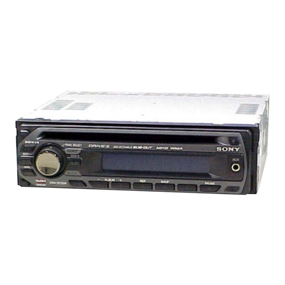
(Photo: CDX-GT22W)
Model Name Using Similar Mechanism
CD Drive Mechanism Type
Optical Pick-up Name
SPECIFICATIONS
Power amplifier section
Outputs
Speaker impedance
Maximum power output
General
Output
Inputs
Tone controls
Loudness
FM/AM COMPACT DISC PLAYER
US Model
CDX-GT22W/GT120/GT220
Canadian Model
CDX-GT22W
NEW
MG-101TC-188//Q
DAX-25A
Speaker outputs (sure seal connectors)
4 – 8 ohms
52 W × 4 (at 4 ohms)
Audio outputs terminal Sub/Rear switchable
Power antenna (aerial) relay control terminal
Power amplifier control terminal
Antenna (aerial) input terminal
AUX input jack (stereo mini jack)
Low: ±10 dB at 60 Hz (XPLOD)
Mid: ±10 dB at 1 kHz (XPLOD)
High: ±10 dB at 10 kHz (XPLOD)
+4 dB at 100 Hz
+2 dB at 10 kHz
– Continued on next page –
Advertisement
Table of Contents

Related Manuals for Sony CDX-GT22W


Summary of Contents for Sony CDX-GT22W
- Page 1 Tuning range 530 – 1,710 kHz Antenna (aerial) terminal External antenna (aerial) connector Intermediate frequency 10.7 MHz/450 kHz Sensitivity 30 µV FM/AM COMPACT DISC PLAYER Sony Corporation 9-887-788-01 eVehicle Division 2007G04-1 Published by Sony Techno Create Corporation © 2007. 07...
- Page 2 THE PARTS LIST ARE CRITICAL TO SAFE OPERATION. CRITIQUES POUR LA SÉCURITÉ DE FONCTIONNEMENT. NE REPLACE THESE COMPONENTS WITH SONY PARTS REMPLACER CES COMPOSANTS QUE PAR DES PIÈCES SONY WHOSE PART NUMBERS APPEAR AS SHOWN IN THIS DONT LES NUMÉROS SONT DONNÉS DANS CE MANUEL OU MANUAL OR IN SUPPLEMENTS PUBLISHED BY SONY.
-
Page 3: Table Of Contents
3-7. Chassis (OP) Assy ............11 3-8. Chucking Arm Sub Assy ..........11 3-9. Sled Motor Assy .............. 12 3-10. Optical Pick-up Section ........... 13 3-11. Optical Pick-up ..............13 * CDX-GT22W/GT220 only DIAGNOSIS FUNCTION ........14 DIAGRAMS • UNLEADED SOLDER 5-1. -
Page 4: Service Note
CDX-GT22W/GT120/GT220 SECTION 1 SERVICE NOTE EXTENSION CABLE AND SERVICE POSITION When repairing or servicing this set, connect the jig (extension cable) as shown below. • Connect the MAIN board (CNP301) and the SERVO board (CN2) with the extension cable (Part No. J-2502-076-1). -
Page 5: General
CDX-GT22W/GT120/GT220 SECTION 2 GENERAL This section is extracted from instruction manual. • LOCATION OF CONTROL Location of controls and basic operations Main unit J DSPL (display)/SCRL (scroll) button The following buttons on the card remote commander have also different buttons/functions (CDX-GT320/GT32W/GT220/GT22W) from the unit. - Page 6 CDX-GT22W/GT120/GT220 CDX-GT320/GT32W Supplied with XA-C40 Fourni avec le XA-C40 Source selector Supplied with the CD/MD changer (not supplied) Fourni avec le changeur de CD/MD Sélecteur de source (non fourni) XA-C40 AUDIO OUT FRONT CDX-GT320 BUS AUDIO IN CDX-GT32W CDX-GT320/GT32W only...
-
Page 7: Disassembly
CDX-GT22W/GT120/GT220 SECTION 3 DISASSEMBLY Note: This set can be disassemble according to the following sequence. 3-1. SUB PANEL ASSY (Page 8) 3-2. CD MECHANISM BLOCK (Page 8) 3-4. SERVO BOARD 3-3. MAIN BOARD (Page 9) (Page 9) 3-5. CHASSIS (T) SUB ASSY (Page 10) 3-6. -
Page 8: Sub Panel Assy
CDX-GT22W/GT120/GT220 Note: Follow the disassembly procedure in the numerical order given. 3-1. SUB PANEL ASSY 3 two claws 2 two claws 1 two screws (+PTT 2.6 × 6) 4 sub panel assy 3-2. CD MECHANISM BLOCK 6 bracket (CD) 7 CD mechanism block 5 two screws (+PTT 2.6 ×... -
Page 9: Main Board
CDX-GT22W/GT120/GT220 3-3. MAIN BOARD 2 two screws (+PTT 2.6 × 8) 4 two screws (+P 2.6 × 8) 5 two screws (+PTT 2.6 × 10) 1 three ground point screws 6 screw (+PTT 2.6 × 6) (+P 2.6 × 10) 7 screw (+PTT 2.6 ×... -
Page 10: Chassis (T) Sub Assy
CDX-GT22W/GT120/GT220 3-5. CHASSIS (T) SUB ASSY 2 two precision screws 1 two precision screws (+P 1.7 × 2.2) (+P 1.7 × 2.2) 4 chassis (T) sub assy 3 claw 3-6. ROLLER ARM ASSY 5 roller arm assy 4 gear (RA1) -
Page 11: Chassis (Op) Assy
CDX-GT22W/GT120/GT220 3-7. CHASSIS (OP) ASSY 6 chassis (OP) assy 1 tension spring (KF) 7 coil spring (damper) (natural) 8 coil spring (damper) (green) 4 slider (R) 3 lever (D) 2 gear (LE1) 3-8. CHUCKING ARM SUB ASSY 3 chucking arm sub assy 1 spring Note: Have this portion receive the chassis. -
Page 12: Sled Motor Assy
CDX-GT22W/GT120/GT220 3-9. SLED MOTOR ASSY 2 three serration screws (M 2 × 3) 3 sled mtor assy 1 spring turn table spring stand Note: Never remove these parts since they were adjusted. stand Note: Place the stand with care not to touch the turn table. -
Page 13: Optical Pick-Up Section
CDX-GT22W/GT120/GT220 3-10. OPTICAL PICK-UP SECTION 2 optical pick-up section Note: Be careful not to touch the lens and hologram terminal when removing the optical pick-up section. 3-11. OPTICAL PICK-UP 1 pan tapping screw (M 1.4 × 2.5) 2 leaf spring (sub guide) -
Page 14: Diagnosis Function
CDX-GT22W/GT120/GT220 SECTION 4 DIAGNOSIS FUNCTION Description of the Diagnostics function: 4. Contents of each display mode 4-1. Reset count display mode 1. Setting the Diag display mode With the power off, press the [4] button, [5] button, and [4] button on the set body or the remote control (for more than 2 seconds) in turn. - Page 15 CDX-GT22W/GT120/GT220 4-5. CD error information display mode 4-6. OFFSET/FAILURE error display mode 4-5-1. Error description 0 6 1 X X X X X 0 5 1 Operating hours Error information Error description Error description Indication Description (in hexadecimal (0: OFFSET, 1: FAILURE)
- Page 16 CDX-GT22W/GT120/GT220 MEMO...
-
Page 17: Diagrams
CDX-GT22W/GT120/GT220 SECTION 5 DIAGRAMS 5-1. BLOCK DIAGRAM — MAIN SECTION — ELECTRONIC VOLUME IC401 J330 AUDIO SUBOUT L R-CH SUBOUT R R-CH REAR I2C BUS CONTROLLED POWER AMP/MULTIPLE MUTE VOLTAGE REGULATOR R-CH Q481 IC750 J901 CN601 9 AUX-LCH 7 AUX-RCH... -
Page 18: Block Diagram -Display Section
CDX-GT22W/GT120/GT220 5-2. BLOCK DIAGRAM — DISPLAY SECTION — • NOTE FOR PRINTED WIRING BOARDS AND SCHEMATIC DIAGRAMS THIS NOTE IS COMMON FOR PRINTED WIRING BOARDS AND SCHEMATIC DIAGRAMS. SYSTEM CONTROL DISPLAY CONTROL (In addition to this, the necessary note is... -
Page 19: Printed Wiring Board -Main Section
CDX-GT22W/GT120/GT220 5-3. PRINTED WIRING BOARD — MAIN SECTION — : Uses unleaded solder. CN601 C464 C775 C774 JW32 FU601 R472 R482 C751 IC750 C765 C764 C771 R432 C763 JW14 C753 C617 R471 C442 JW16 R442 JW19 D617 C432 JW15 C445... -
Page 20: Schematic Diagram -Main Section (1/4)
CDX-GT22W/GT120/GT220 5-4. SCHEMATIC DIAGRAM — MAIN SECTION (1/4) — • Refer to page 26 for IC Block Diagrams. J330 C464 C454 C431 R431 Q431 R432 IC401 C412 C401 C413 Q451 R452 C404 C405 C451 R451 C406 C407 C441 R441 Q441... -
Page 21: Schematic Diagram -Main Section (2/4)
CDX-GT22W/GT120/GT220 5-5. SCHEMATIC DIAGRAM — MAIN SECTION (2/4) — • Refer to page 26 for IC Block Diagrams. C775 C765 C764 C774 C751 D751 D752 C750 D753 IC B/D D754 JC754 JC755 D755 D756 IC750 D757 D758 C435 C432 CN601... -
Page 22: Schematic Diagram -Main Section (3/4)
CDX-GT22W/GT120/GT220 • Refer to page 18 for Waveforms. 5-6. SCHEMATIC DIAGRAM — MAIN SECTION (3/4) — • Refer to page 27 for IC Pin Description of IC501. (Page 20) (Page 21) D511 R519 R531 R556 R690 R536 R535 R558 R533... -
Page 23: Schematic Diagram -Main Section (4/4)
CDX-GT22W/GT120/GT220 5-7. SCHEMATIC DIAGRAM — MAIN SECTION (4/4) — (Page 21) (Page 20) JC681 FB604 C153 C151 C152 R155 IC602 C623 R153 R154 D719 R601 C622 L151 R151 R152 C519 C154 C155 CN701 Q631 (Page 22) R541 R633 R631 C631... -
Page 24: Printed Wiring Board -Key Section
CDX-GT22W/GT120/GT220 5-8. PRINTED WIRING BOARD — KEY SECTION — : Uses unleaded solder. LED941, LED942 LED942, LED944, S901 S902 S903 S902 LED931 (LCD BACK LIGHT) S901 R902 R943 S903 LED943 LED951 LCD901 LSW901 LIQUID CRYSTAL DISPLAY PANEL LSW904 LSW903 R948... -
Page 25: Schematic Diagram -Key Section
CDX-GT22W/GT120/GT220 5-9. SCHEMATIC DIAGRAM — KEY SECTION — R943 R945 R949 R951 LED951 LED941 R931 R981 R932 R982 R975 R941 IC971 LSW903(2/2) LSW905(2/2) LSW911(2/2) R971 R933 C971 R942 LED931 LSW906(2/2) LSW901(2/2) LED944 LSW908(2/2) LSW910(2/2) R947 LED952 LED943 C981 C983 R984... - Page 26 CDX-GT22W/GT120/GT220 • IC Block Diagrams IC401 BD3442FS-E2 (MAIN Board (1/4)) IC750 TDA8588BJ/N2/R1 (MAIN Board (2/4)) BUS-L 32 FIL VCC2 OUT-FL- C BUS 100k 31 GND BUS-R OUT-FL+ INPUT INPUT VOLUME1 TREBLE VOLUME2 100k SELECTOR GAIN /MUTE /BASS TU-L 3 30 SDA...
- Page 27 CDX-GT22W/GT120/GT220 • IC PIN DESCRIPTIONS • IC501 MB90F045PF-G-9065-SPE1 (SYSTEM CONTROL) (MAIN BOARD (3/4)) Pin No. Pin Name Pin Description AREASEL0 Destination function setting pin 0 AREASEL1 Destination function setting pin 1 AREASEL2 Destination function setting pin 2 AREASEL3 Destination function setting pin 3...
- Page 28 CDX-GT22W/GT120/GT220 Pin No. Pin Name Pin Description CODEC_SEL MP3 select signal input “H”: MP3, “L”: Non-MP3 ILLUMI SEL Illumination voltage setting signal input “H”: 10.4 V, “L”: 9.0 V Not used. (Open) SIRCS Remote control signal input 65 to 67 Not used.
-
Page 29: Exploded Views
CDX-GT22W/GT120/GT220 SECTION 6 EXPLODED VIEWS NOTE: • The mechanical parts with no reference • -XX and -X mean standardized parts, so The components identified by mark 0 or dotted line with mark number in the exploded views are not supplied. -
Page 30: Front Panel Section
A-1317-411-A PANEL COMPLETE ASSY, FRONT (GT120) 1-780-533-11 CONDUCTIVE BOARD, CONNECTION X-2178-983-1 BUTTON ASSY (S) 3-214-226-11 ILLUMINATOR (LCD) 3-251-320-01 EMBLEM (NO. 2.5), SONY 3-214-215-01 PANEL, BACK A-1286-073-A PANEL SUB ASSY, FRONT (GT22W) 3-250-543-91 SCREW (+B P-TITE M2) A-1286-350-A PANEL SUB ASSY, FRONT (GT220) -
Page 31: Cd Mechanism Section (Mg-101Tc-188//C)
CDX-GT22W/GT120/GT220 6-3. CD MECHANISM SECTION (MG-101TC-188//C) not supplied not supplied not supplied not supplied not supplied not supplied not supplied not supplied not supplied not supplied not supplied Ref. No. Part No. Description Remark Ref. No. Part No. Description Remark A-1283-704-A MECHANICAL BLOCK ASSY (08) 3-348-998-31 SCREW (M1.4X2.5), TAPPING, PAN... -
Page 32: Electrical Parts List
CDX-GT22W/GT120/GT220 SECTION 7 ELECTRICAL PARTS LIST NOTE: • Due to standardization, replacements in • Items marked “*” are not stocked since The components identified by mark 0 or dotted line with mark the parts list may be different from the they are seldom required for routine service. - Page 33 CDX-GT22W/GT120/GT220 MAIN Ref. No. Part No. Description Remark Ref. No. Part No. Description Remark R912 1-216-824-11 METAL CHIP 1.8K 1/10W A-1286-340-A MAIN BOARD, COMPLETE (GT22W/GT220) R913 1-216-825-11 METAL CHIP 2.2K 1/10W A-1317-388-A MAIN BOARD, COMPLETE (GT120) R914 1-216-827-11 METAL CHIP 3.3K...
- Page 34 CDX-GT22W/GT120/GT220 MAIN Ref. No. Part No. Description Remark Ref. No. Part No. Description Remark C509 1-162-966-11 CERAMIC CHIP 0.0022uF 10% D754 6-501-362-01 DIODE 1A4-TA26 C510 1-162-970-11 CERAMIC CHIP 0.01uF D755 6-501-362-01 DIODE 1A4-TA26 C511 1-124-584-00 ELECT 100uF D756 6-501-362-01 DIODE 1A4-TA26...
- Page 35 CDX-GT22W/GT120/GT220 MAIN Ref. No. Part No. Description Remark Ref. No. Part No. Description Remark < RESISTOR > R533 1-216-845-11 METAL CHIP 100K 1/10W R534 1-216-833-11 METAL CHIP 1/10W 1-216-821-11 METAL CHIP 1/10W R535 1-216-833-11 METAL CHIP 1/10W 1-414-595-11 INDUCTOR, FERRITE BEAD...
- Page 36 CDX-GT22W/GT120/GT220 MAIN SERVO Ref. No. Part No. Description Remark < TUNER UNIT > A-3220-961-B TUNER UNIT (TUX-032) < VIBRATOR > X501 1-813-524-21 VIBRATOR, CERAMIC (18.432MHz) X502 1-767-317-11 VIBRATOR, CRYSTAL (32.768kHz) ************************************************************* A-1201-631-A SERVO BOARD, COMPLETE ********************** ************************************************************* MISCELLANEOUS *************** 1-833-974-31 CONNECTION CORD FOR AUTOMOBILE...
- Page 37 CDX-GT22W/GT120/GT220 MEMO...
- Page 38 CDX-GT22W/GT120/GT220 REVISION HISTORY Clicking the version allows you to jump to the revised page. Also, clicking the version at the top of the revised page allows you to jump to the next revised page. Ver. Date Description of Revision 2007. 07...
Need help?
Do you have a question about the CDX-GT22W and is the answer not in the manual?
Questions and answers