Table of Contents
Advertisement
Quick Links
SMART TEMP
PROGRAMMABLE OR NON-PROGRAMMABLE THERMOSTAT
(FOR BOTH CONVENTIONAL AND HEAT PUMP SYSTEMS)
I N S TA L L AT I O N A N D O P E R AT I N G I N S T R U C T I O N S
• Please read all of these instructions carefully before beginning
installation.
• Label every wire terminal designation on your existing thermostat wiring
before removing your old thermostat.
• Ignore the color of the wires since they may not comply with any
standard. Please connect wires using the terminal letter designations.
Thank you for your confidence in our product. To obtain the best results from
your investment, please read and follow the installation procedures carefully, and
one step at a time. This will save you time and minimize the chance of damaging
either the thermostat or possibly your heating and cooling system. These
instructions may contain information beyond that which may be required for your
particular installation.
CAUTIONS AND WARNINGS . . . . . . . . . . 2
SYSTEM COMPATIBILITY . . . . . . . . . . . . 3
FEATURES . . . . . . . . . . . . . . . . . . . . . . . 4
TOOLS YOU MAY NEED . . . . . . . . . . . . . . 4
MOUNTING LOCATION . . . . . . . . . . . . . . 5
REMOVE OLD THERMOSTAT . . . . . . . . . . 5
INSTALL THERMOSTAT BASE . . . . . . . . . 6
WIRING INFORMATION . . . . . . . . . . . . . . 6
WIRING DIAGRAMS . . . . . . . . . . . . . . . . 8
COMPLETE THE INSTALL . . . . . . . . . . . 17
WARNING: Use Energizer
Energizer
DURACELL
© 2013 LUX PRODUCTS CORPORATION. ALL RIGHTS RESERVED
All manuals and user guides at all-guides.com
®
UNIVERSAL 5/2-DAY
IMPORTANT!
®
or DURACELL
®
is a registered trademark of Eveready Battery Company, Inc.
®
is a registered trademark of The Procter & Gamble Company
P 5 2 1 U a
FRONT PANEL ITEMS . . . . . . . . . . . . . . 17
OPTIONS . . . . . . . . . . . . . . . . . . . . . . . 19
OPERATING INSTRUCTIONS . . . . . . . . . 21
TEMPERATURE PROGRAMS . . . . . . . . . 23
ADVANCED FEATURES . . . . . . . . . . . . . 24
BATTERY REPLACEMENT . . . . . . . . . . . 28
TECHNICAL ASSISTANCE . . . . . . . . . . . 29
LIMITED WARRANTY . . . . . . . . . . . . . . 29
MERCURY NOTICE . . . . . . . . . . . . . . . . 30
®
Alkaline Batteries Only.
52135
Advertisement
Table of Contents

Subscribe to Our Youtube Channel
Related Manuals for Lux Products LuxPro SMART TEMP P521Ua


Summary of Contents for Lux Products LuxPro SMART TEMP P521Ua
-
Page 1: Table Of Contents
WARNING: Use Energizer ® or DURACELL ® Alkaline Batteries Only. Energizer ® is a registered trademark of Eveready Battery Company, Inc. DURACELL ® is a registered trademark of The Procter & Gamble Company © 2013 LUX PRODUCTS CORPORATION. ALL RIGHTS RESERVED... -
Page 2: Cautions And Warnings
All manuals and user guides at all-guides.com CAUTIONS AND WARNINGS: • This thermostat requires batteries to operate and failure or sub-standard performance of the batteries may impair or prevent the correct operation of the thermostat. Use Duracell ® or Energizer ®... -
Page 3: System Compatibility
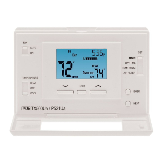
All manuals and user guides at all-guides.com P521Ua LCD Display Screen Fan Mode Set Slide Switch AUTO Switch DAY/TIME TEMP PROG AIR FILTER TEMPERATURE HEAT HOLD EMER COOL NEXT System Mode Switch UP, DOWN and HOLD Buttons SYSTEM COMPATIBILITY: The electrical rating for this thermostat is 1.5 Amps per terminal, with a maximum total combined load of 3.0A for all terminals combined. -
Page 4: Features
All manuals and user guides at all-guides.com FEATURES: • 1 or 2-Heat / 1-Cool, 5/2-day programming • Universal Compatibility for all system types • Weekdays and Weekends can be programmed separately • Exclusive LUX ® Speed Slide for easy programming •... -
Page 5: Mounting Location
All manuals and user guides at all-guides.com MOUNTING LOCATION: On replacement installations, mount the new thermostat in place of the old one unless the conditions listed below suggest otherwise. On new installations, please follow these general guidelines: 1. Mount the thermostat on an inside wall, about 5 ft. (1.5m) above the floor. 2. -
Page 6: Install Thermostat Base
All manuals and user guides at all-guides.com INSTALL THERMOSTAT BASE: THERMOSTAT TOP VIEW 1. Strip wire insulation leaving only 3/8 in. (9.5mm) bare wire ends, and clean off any corrosion present. 2. Fill the wall opening with non-combustible insulation to prevent drafts from affecting the thermostat’s normal operation. - Page 7 All manuals and user guides at all-guides.com WIRING DIAGRAM NOTES: (Important, please read all notes before connecting wires) • If the information provided in the following wiring diagrams does not clearly represent or match your system, please refer to the “TECHNICAL ASSISTANCE” section of this manual, and contact us before removing any of your existing thermostat wiring.
-
Page 8: Wiring Diagrams
All manuals and user guides at all-guides.com WIRING DIAGRAMS: DIAGRAM SYSTEM TYPE / DESCRIPTION PAGE # CONVENTIONAL: HEATING ............9 1-STAGE OR 2-STAGE 2, 3, 4, 5 WIRES CONVENTIONAL: HEATING ............10 3-WIRE ZONE VALVE 3, 4 WIRES CONVENTIONAL: COOLING ............11 1-STAGE 3, 4 WIRES CONVENTIONAL: HEATING AND COOLING ........12... - Page 9 All manuals and user guides at all-guides.com...
- Page 10 All manuals and user guides at all-guides.com...
- Page 11 All manuals and user guides at all-guides.com...
- Page 12 All manuals and user guides at all-guides.com...
- Page 13 All manuals and user guides at all-guides.com...
- Page 14 All manuals and user guides at all-guides.com...
- Page 15 All manuals and user guides at all-guides.com...
- Page 16 All manuals and user guides at all-guides.com...
-
Page 17: Complete The Install
All manuals and user guides at all-guides.com COMPLETE THE INSTALL: INSTALL BATTERIES INTO THERMOSTAT: Install two brand new Energizer ® DURACELL ® “AA” size alkaline (only) batteries, into the thermostat’s battery compartment. Ensure the batteries are installed in the proper direction. GAS / ELEC CIRCUIT BOARD OPTION (“G”... - Page 18 All manuals and user guides at all-guides.com with or without a demand for heating or cooling, even when the System Mode switch is in the OFF position. NOTE: The Fan Mode switch only works if your system provides a wire for the thermostat’s “G”...
-
Page 19: System Configuration And Setup Options
All manuals and user guides at all-guides.com SYSTEM CONFIGURATION AND SETUP OPTIONS: Setup options for how the thermostat will function, along with choosing your particular system type, are performed using a menu on the display screen. TO ACCESS THE SETUP MENU: Move the System Mode switch into the OFF position, and then hold down the EMER button for approximately 5 seconds until the screen changes. - Page 20 All manuals and user guides at all-guides.com ITEM #07 (DLAY = DELAY TIME): [5, default] Thermostat waits 5 minutes before turning the system back on after it was last run. This internal delay prevents rapid cycling and provides equipment protection. The 5 minute setting is fine for most applications.
-
Page 21: Operating Instructions
All manuals and user guides at all-guides.com OPERATING INSTRUCTIONS: SET DAY AND TIME: Place the Set Slide Switch into the DAY/TIME position. With the day flashing, press UP or DOWN to set the day of the week. Press NEXT and the clock time will start flashing. - Page 22 All manuals and user guides at all-guides.com characteristics, you should refer to your heat pump literature to determine when to disable the heat pump and run in Emergency Heat mode. In general for most heat pump systems, use Emergency Heat mode whenever the outside temperature is less than 32°F (0°C) degrees.
-
Page 23: Temperature Programs
All manuals and user guides at all-guides.com TEMPERATURE PROGRAMS: By default, this thermostat has 4 separate program periods for both Heat and Cool mode, they are: MORN, DAY, EVE, and NITE. Each period ends at the start time of the following period. The heat programs are set in HEAT mode, and the cool programs are set in COOL mode. -
Page 24: Advanced Features
All manuals and user guides at all-guides.com ADVANCED FEATURES: TEMPERATURE CALIBRATION: The internal temperature sensor in this thermostat is accurately calibrated at the factory, and in most cases alterations to this setting should not be needed. The Temperature Calibration feature allows you to manually offset the measured temperature by as much as plus or minus 5°F (3°C) degrees from its original value. - Page 25 All manuals and user guides at all-guides.com NEXT button to accept the setting. If the code you tried was not correct, the thermostat will exit and return to the Normal Run screen with no changes made. If the entered code is correct, the screen will add the word “SET” and display the current heat set temperature limit.
- Page 26 All manuals and user guides at all-guides.com KEYPAD LOCKOUT: You can lock the front panel buttons to prevent unauthorized tampering of your thermostat settings. NOTE: These keypad lock instructions need to be performed in a timely manner. The 4-button sequence which locks the thermostat must be entered within a 10- second timeframe, or the keypad lockout sequence will have to be entered again from the beginning.
- Page 27 All manuals and user guides at all-guides.com TO RESET THE FILTER USAGE COUNTER: Move the Set Slide switch to the “AIR FILTER” position. The three small digits at the top of the screen tell you the quantity of filter days remaining. Press both the UP and DOWN buttons together, and the usage counter will return to the beginning of the value that it originally started counting from.
-
Page 28: Battery Replacement
All manuals and user guides at all-guides.com BATTERY REPLACEMENT: This thermostat is powered by two “AA” Alkaline batteries. The batteries should be replaced AT LEAST once per year to ensure reliable operation (or sooner if “LO BATT” appears in the display screen). The batteries are located on the back of the thermostat’s circuit board. -
Page 29: Technical Assistance
All manuals and user guides at all-guides.com TECHNICAL ASSISTANCE: If you have any problems installing or using this thermostat, please carefully and thoroughly review the instruction manual. If you require assistance, please contact our Technical Assistance department at 856-234-8803 during regular business hours between 8:00AM and 4:30PM Eastern Standard Time, Monday through Friday. -
Page 30: Mercury Notice
All manuals and user guides at all-guides.com MERCURY WARNING AND RECYCLING NOTICE: Mercury is considered to be a hazardous material. If this product is replacing a thermostat that contains mercury in a sealed tube, contact your local waste management authority for instructions regarding recycling and proper disposal. It may be unlawful in your state to place it in the trash.
Need help?
Do you have a question about the LuxPro SMART TEMP P521Ua and is the answer not in the manual?
Questions and answers