Table of Contents
Advertisement
Quick Links
LUX Products Corporation - Mt. Laurel, New Jersey 08054 - http://www.luxproproducts.com
Thank you for your confidence in our product. To obtain the best results from your investment, please read these
instructions and acquaint yourself with your purchase. Follow the installation procedures carefully, and save these
instructions for future reference. This will save you time and minimize the chance of damaging either the thermostat or
the systems that it controls.
SYSTEM COMPATIBILITY:
This thermostat can be used with most single-stage 24 volt: gas, oil or electric heating and cooling systems, single-stage
heat pumps, or gas Millivolt heating systems.
It cannot be used with: 3-wire zone valves, 120/240 volt heating elements, or multi-stage heat pumps. Ask your dealer
for other LUXPRO thermostats to control those systems.
THERMOSTAT FEATURES:
• 1-Stage Heat / 1-Stage Cool
• Electronic Accuracy
• Innovative SAVE Feature
• Gas / Elec Fan Option
• Battery Powered Only
• Set Temperature Range 45°F (7°C) degrees to 90°F
(32°C) degrees
• Clean, Attractive Design
• LuxLight
®
Illuminated Display Screen
• Easy to Install
I N S TA L L AT I O N A N D
O P E R AT I N G I N S T R U C T I O N S
Non-Programmable Thermostat
WARNING: Use Energizer
®
Energizer
®
is a registered trademark of Eveready Battery Company, Inc.
DURACELL
®
is a registered trademark of The Procter & Gamble Company
PSDS11b
Lighted
or DURACELL
®
Alkaline Batteries Only.
• Large, Easy to Read Display
• F/C Selectable Temperature Display
• Adjustable Temperature Differential / Cycle Rate
• User Temperature Display Calibration
• 5/2 Minute Selectable Minimum Run/Off Time
• On-Screen Low Battery Indicator
• 3-Year Warranty
• No Leveling Required
52157
1
Advertisement
Table of Contents

Related Manuals for Lux Products PSDS11b


Summary of Contents for Lux Products PSDS11b
- Page 1 O P E R AT I N G I N S T R U C T I O N S 52157 PSDS11b Lighted Non-Programmable Thermostat LUX Products Corporation - Mt. Laurel, New Jersey 08054 - http://www.luxproproducts.com WARNING: Use Energizer ® or DURACELL ®...
-
Page 2: Tools You May Need
TOOLS YOU MAY NEED: Screwdrivers, wire stripper / cutter, and possibly a drill with assorted bits (new installations only). REMOVAL OF OLD THERMOSTAT: 1. Turn OFF the electricity to all heating and cooling components. Do not turn the electricity back on until all work is completed. -
Page 3: System Configuration And Setup Options
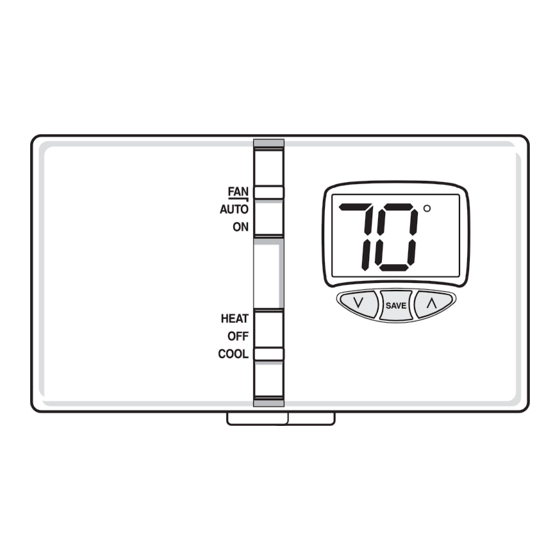
WIRING TERMINAL CONNECTIONS: 1. When attaching the wires to the thermostat, please ensure that the bare wire ends are held ALL the way into the terminal block while the screw is being tightened. 2. Securely tighten all of the electrical terminal screws, including any unused ones. Be careful not to over tighten the screws, they only need to be snug. - Page 4 OPERATING INSTRUCTIONS: HEAT / OFF / COOL, SYSTEM MODE SWITCH: Set this switch to HEAT to control your heating system, and COOL to control your cooling system. The OFF position will disable both the heating and cooling units. AUTO / ON, FAN SWITCH: When this switch is in AUTO, the blower fan (if present in your system) will automatically cycle on and off by itself when heating or cooling is running.
-
Page 5: Advanced Features
ADVANCED FEATURES: TEMPERATURE SWING: The amount of temperature variation between load-on and load-off is changed by adjusting the swing setting. The default value for this thermostat is #4, and the adjustment range is from #1 to #9. A smaller swing number makes the temperature control more precise and constant, and increases the number of cycles per hour. -
Page 6: Technical Support
LIMITED WARRANTY: If this unit fails because of defects in materials or workmanship within three years of the date of original purchase, LUX will, at its option, repair or replace it. This warranty does not cover damage by accident, misuse, or failure to follow installation instructions. -
Page 7: Wiring Diagram Notes
WIRING DIAGRAM NOTES: 1. The BOLD lines are what you should be connecting to the terminals on this new thermostat. 2. The DASHED lines are optional depending upon your system type. 3. In many cases, the thin lines shown as “SYSTEM COMMON” will not be visible at the thermostat location, they are located with your heating and cooling equipment. - Page 8 4, 5 WIRES CONVENTIONAL (NON HEAT PUMP) 1-STAGE HEATING AND 1-STAGE COOLING Factory RH-RC Jumper Wire Installed COMMON HEATER CONDITIONER POWER BLACK TERMINAL LETTERS ARE TYPICAL, GRAY TERMINAL LETTERS ARE BRAND SPECIFIC SINGLE-STAGE HEAT PUMP SYSTEM 4, 5 WIRES WITH NO AUX OR EMERGENCY HEAT ** Use “O”...
Need help?
Do you have a question about the PSDS11b and is the answer not in the manual?
Questions and answers