Table of Contents
Advertisement
Quick Links
快速安裝指南 Kurzanleitung Guide rapide Guía rápida
XH510G Quick Guide
クイックガイド Kраткое руководство 快速安裝指南
More information on this product can be found at: https://bit.ly/S-XH510G
更多本產品資訊,請蒞臨:https://bit.ly/S-XH510G
Weitere Informationen zu diesem Produkt finden Sie unter: https://bit.ly/S-XH510G
Pour plus d'informations sur ce produit, visitez: https://bit.ly/S-XH510G
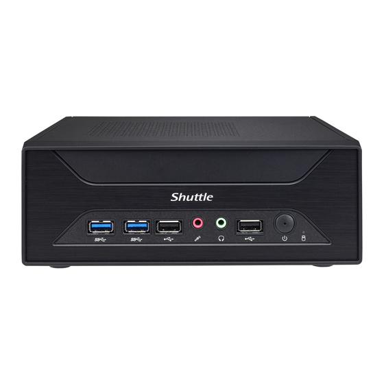
Product Overview
產品外觀 \ Produktübersicht \ Présentation du produit \ Resumen del producto \ 製品概要 \ Обзор продукта \ 产品外观
1
2
3
4
2
5
1. USB 2.0 Ports
2. USB 3.2 Gen1 Type-A Ports
3. MIC-in
4. Headphones
5. Power switch / Power LED
10. LAN Port
Hardware Installation
硬體安裝 \ Hardware Installation \ Installation du matériel \ Instalación de hardware \ ハードウェアのインストール \ Установка оборудования \硬件安装
For safety reasons, please ensure that the power
!
cord is disconnected before opening the case.
1. Turn your XH510G upside down,
then unscrew one screw of the
HDD/SSD cover and remove it.
a
Install the M.2 SSD, if required
(refer step D).
c
M.2 M KEY connector
(For 2280 SATA port only)
The maximum permitted size
!
for an internal USB device is
11.5 mm x 28 mm x 88 mm.
2. Mount the HDD/SSD into the
bracket with three screws.
a
b
The product's colour and specifications may vary from the actually shipping product.
L
B. CPU and ICE Module Installation
1. Unscrew the two thumbscrews of
|the chassis cover. Slide the cover
backwards and upwards.
c
b
2. Unfasten the four ICE module attachment screws and unplug the fan
connector. Remove the ICE module from the chassis and put it aside.
a
b
c
FAN1
Follow the steps below to correctly install the CPU into the
motherboard CPU socket.
This CPU socket is fragile and can easily be damaged. Always
!
use extreme care when installing a CPU and limit the number of
times you remove or change the CPU. Before installing the CPU,
make sure to turn off the computer and unplug the power cord
from the power outlet to prevent damage of the CPU.
3. Unlock and raise
the socket lever.
4. Lift the metal load
plate off the CPU
socket.
DO NOT touch the socket contacts. To protect the CPU socket,
!
always use the protective socket cover when the CPU is not
installed.
Puede encontrar más información sobre este producto en: https://bit.ly/S-XH510G
本製品の詳細な情報については、次のURLより確認頂けます。https://bit.ly/S-XH510G
Для получения дополнительной информации об этом продукте перейдите по ссылке: https://bit.ly/S-XH510G
更多本产品信息,请访问:https://bit.ly/S-XH510G
13
15
10
6
7
8
9
6. Hard disk drive LED
11. Power Jack (DC IN)
7. COM port (optional)
12. Clear CMOS & Power Button & +5V
8. HDMI 2.0 Port
13. Wireless LAN perforation (optional)
9. DisplayPort
14. PCIe x16 slot (optional)
15. Kensington
®
Lock hole
3. Tear off the adhesive tape of the HDD cable. Install the HDD or
SSD in the chassis using its bracket. Affix with three screws and
connect the HDD or SSD with an HDD cable.
c
b
b
9.5mm
2.5" SATA HDD/SSD
2.95mm
Motherboard
4. Replace the HDD/SSD cover
and refasten the screw.
5. Please orientate the CPU correctly and align the CPU notches
with the socket alignment keys. Make sure the CPU sits perfectly
horizontal, then push it gently into the socket.
Align the CPU notches with
the socket alignment keys.
Triangle Pin1 Marking on the CPU
a
Please be aware of the CPU orientation, DO NOT force the
!
CPU into the socket to avoid bending of pins on the socket and
damage of CPU!
6. Tear off the protective membrane
from the metal load plate.
Close the metal load plate,
lower the CPU socket lever
and lock in place.
a
Tear off the protective membrane
7. Spread thermal paste evenly
on the CPU surface.
Thermal Paste
application area
a
!
Please do not apply excess amount of thermal paste.
b
8. Screw the ICE module to the motherboard. Note to press down
on the opposite diagonal corner while tightening each screw.
9. Connect the fan.
d
b
e
a
53R-XH5103-2201
C. Memory Module Installation
This motherboard does only support 1.2 V DDR4 SO-DIMM
!
memory modules.
1. Locate the SO-DIMM slots on the motherboard.
2. Align the notch of the memory module with the one of the relevant
memory slot.
14
13
3. Gently insert the module into the slot in a 45-degree angle.
11
12
2
1
4. Carefully push down the memory module until it snaps into the
locking mechanism.
b
HDD/SSD cable
a
Latch
5. Repeat the above steps to install an additional memory module,
if required.
1. Unfasten the expansion slot bracket screw.
Remove the back panel bracket and put it aside.
The maximum permitted size for display cards is 208.5 mm x 120 mm x 30 mm.
!
The display cards must be installed on the riser card, not on the motherboard.
a
M.2 M KEY connector
b
1. Replace the cover and tighten the thumbscrews, then connect the power cord.
2. Complete.
b
Follow the steps 1-2 to install the VESA mount.
b
c
!
Supports 75x75 mm and 100x100 mm VESA standard.
Safety Information
Incorrectly replacing the battery may damage this computer.
!
Replace only with the same or equivalent as recommended by Shuttle.
Dispose of used batteries according to the manufacturer's instructions.
更換電池方式錯誤可能會損壞本電腦以及引發爆炸、火災或其他危險。僅能依
Shuttle的建議,以相同或同等的電池更換。請依照製造商的使用說明處理廢電池。
Das unkorrekte Austauschen der Batterie kann diesen Computer beschädigen.
Ersetzen Sie die Batterie nur durch den von Shuttle empfohlenen Typ oder
ein gleichwertiges Modell. Entsorgen Sie gebrauchte Batterien gemäß den
Herstellerangaben.
Ne pas replacer correctement la pile peut endommager l'ordinateur. Remplacez-
la uniquement par un modèle identique ou un équivalent comme recommandé
par Shuttle. Débarrassez-vous des piles usagées d'après les instructions du
constructeur.
This device complies with Part 15 of the FCC Rules. Operation is subject to
the following two conditions: (1) this device may not cause harmful interference,
c
and (2) this device must accept any interference received, including interference
f
that may cause undesired operation.
This device meets the requirements for the EU conformity in accordance
to the currently valid EU directives.
FAN1
Dieses Produkt erfüllt die Anforderungen für die EU-Konformität entsprechend der
aktuell geltenden EU-Richtlinien.
Ce produit répond aux exigences de la conformité UE suivant les directives
européennes actuellement en vigueur.
D. M.2 Device Installation
1. Locate the M.2 key slots on the motherboard.
M.2 2242/2260/2280 M key slot
a
SO-DIMM slot
Notch
Cutout
2. Install the M.2 device into the M.2 slot and secure with the screw.
M.2 2242/2260/2280 M key slot
a
1. Use a flat-blade screwdriver to gently pry the metal tab to disengage
the battery from the battery holder.
45-degree
angle
2. Install the new battery, press it on the battery holder keeping
the positive side facing top.
b
Latch
c
a
d
c
DC-IN
!
M4x10 * 4pcs
1
安全資訊 \ Sicherheitshinweise \ Informations de sécurité \ Información de seguridad \ 安全に関する情報 \ Информация о безопасности \ 安全信息
La sustitución incorrecta de la batería puede dañar este equipo. Sustituya la batería
únicamente por una igual o equivalente recomendada por Shuttle. Deseche las
baterías usadas según las instrucciones del fabricante.
バッテリを間違ってセットすると、このコンピュータが損傷する原因となります。
交換する際は、Shuttle が推奨するバッテリと同じものまたは同等のものだけを使用
するようにしてください。使用済みバッテリは、メーカーの指示に従って処分して
ください。
Неправильная замена батареи может привести к повреждению компьютера. Батарея
должна соответствовать стандарту производителя Shuttle или быть идентичной пред
ыдущей. Утилизация использованной батареи должна следовать инструкции произво
дителя.
更换电池方式错误可能会损坏本电脑。仅能依 Shuttle 的建议,以相同或同等的电池更
换。请依照制造商的使用说明处理废电池。
注意: 仅适用于在非热带气候条件下安全使用, 在热带气候条件下使用时,
可能有安全隐患。
注意: 允许产品使用的最高环境温度为 40℃。
注意: 仅适用于海拔 2000m 以下安全使用, 在海拔 2000m 以上使用时,
可能有安全隐患。
All bundled parts, power cord included, shall not be used without this product.
電源ケーブル等、すべての付属品は本機以外ではご使用になれません。
M.2 2230 E Key slot
b
a
b
Slope angle
Slope angle
M.2 2230 E Key slot
Metal tab
a
2. Install the PCIe x16 card into the PCIe x16 slot.
Secure the bracket.
b
a
PCIe x16 slot
f
e
Please press the "Del" key while booting to enter
BIOS. Here, please load the optimised BIOS settings.
XH510G
Front Panel
M3x7 * 4pcs
2
2000m
Advertisement
Table of Contents

Related Manuals for Shuttle XH510G


Summary of Contents for Shuttle XH510G
- Page 1 更多本產品資訊,請蒞臨:https://bit.ly/S-XH510G 本製品の詳細な情報については、次のURLより確認頂けます。https://bit.ly/S-XH510G memory modules. Weitere Informationen zu diesem Produkt finden Sie unter: https://bit.ly/S-XH510G Для получения дополнительной информации об этом продукте перейдите по ссылке: https://bit.ly/S-XH510G Pour plus d'informations sur ce produit, visitez: https://bit.ly/S-XH510G 更多本产品信息,请访问:https://bit.ly/S-XH510G M.2 2242/2260/2280 M key slot M.2 2230 E Key slot 1.
- Page 2 D. M.2 Device Installation \ M.2 裝置安裝 \ Installation der M.2-Karten 將HDD硬碟或SSD固態硬碟放入支架中, 鎖緊螺絲。 Dé la vuelta al XH510G y suelte un tornillo para retirar la tapa de la unidad de disco. Installation des cartes M.2 \ Instalación de las tarjetas M.2 Поместите...
- Page 3 主機板說明 \ Mainboard-Abbildung \ Illustration de la carte mère \ Ilustración de la placa base Jumper 設定 \ Jumper-Einstellungen \ Réglages cavaliers \ Configuración de los puentes Jumper Settings Motherboard Illustration メインボード図 \ Материнская плата . Иллюстрация \ 主机板说明 ジャンパー設定 \ Настройки переключателя \ Jumper 设定 VGA Connector USB connector \ USB 插座...
Need help?
Do you have a question about the XH510G and is the answer not in the manual?
Questions and answers