Table of Contents
Advertisement
Quick Links
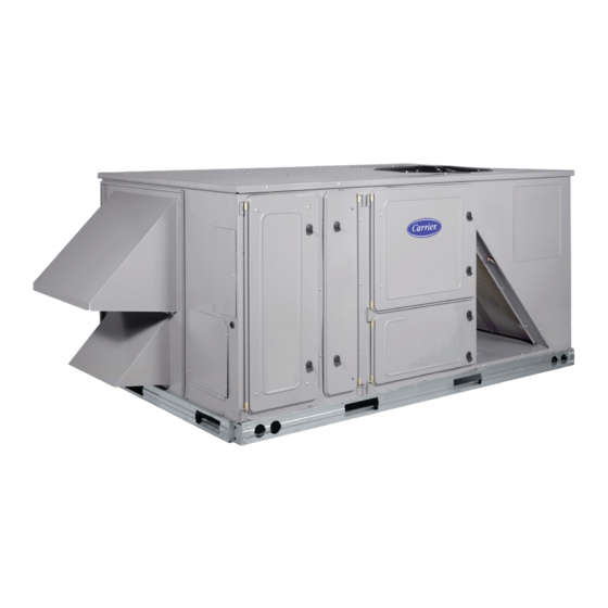
50PG08---14
Single Package Rooftop Units
Electric Cooling with PURONR (R---410A) Refrigerant
and COMFORTLinkt Controls
IMPORTANT: This installation instruction contains basic unit
installation information including installation of field control
devices. For information on unit start-up, service, and operation,
refer to the unit Controls, Start-Up, Operation, Service, and
Troubleshooting Instructions also enclosed in the unit literature
packet.
TABLE OF CONTENTS
. . . . . . . . . . . . . . . . . . . . . . . . . . . . . . . . . . . .
. . . . . . . . . . . . . . . . . . . . . . . . . . .
SAFETY CONSIDERATIONS
Installation and servicing of air-conditioning equipment can be
hazardous due to system pressure and electrical components. Only
trained and qualified service personnel should install, repair, or
service air-conditioning equipment.
Untrained personnel can perform the basic maintenance functions
of replacing filters. All other operations should be performed by
trained service personnel. When working on air-conditioning
equipment, observe precautions in the literature, tags and labels
attached to the unit, and other safety precautions that may apply.
Follow all safety codes. Wear safety glasses and work gloves. Use
quenching cloth for unbrazing operations. Have fire extinguishers
available for all brazing operations.
Recognize safety information. This is the safety- -alert symbol
When you see this symbol on the furnace and in instructions or
manuals, be alert to the potential for personal injury.
Understand the signal words DANGER, WARNING, and
CAUTION. These words are used with the safety- -alert symbol.
DANGER identifies the most serious hazards which will result in
severe personal injury or death. WARNING signifies a hazard
which could result in personal injury or death. CAUTION is used
to identify unsafe practices which may result in minor personal
injury or product and property damage. NOTE is used to highlight
suggestions which will result in enhanced installation, reliability, or
operation.
Installation Instructions
PAGE
. . . . . . . . . . . . . . . . . . . . . . . . .
. . . . . . . . . . . . . . . . . . . . . . . . .
. . . . . . . . . . . . . . . . . . . . . .
. . . . . . . . . . . . . . . . . . .
. . . . . . . .
. . . . . . . . . . . . . . . . . . .
. . . . . . . . . . . . . . . . . . . . .
. . . . . . . . . . . . . . . . . . . . . . .
. . . . . . . . . . . . . . . . . . . . . . . .
WARNING
!
ELECTRICAL SHOCK HAZARD
Failure to follow this warning could cause personal
injury or death.
Before performing service or maintenance operations
on unit, turn off main power switch to unit and install
lockout tag. Ensure electrical service to rooftop unit
1
agrees with voltage and amperage listed on the unit
rating plate.
1
1
4
WARNING
!
6
6
UNIT OPERATION AND SAFETY HAZARD
6
Failure to follow this warning could cause personal
injury, death and/or equipment damage.
7
Puron (R- -410a) refrigerant systems operate at higher
pressures than standard R- -22 systems. Do not use R- -22
19
service equipment or components on Puron refrigerant
19
equipment.
19
IMPORTANT: Units have high ambient operating limits. If limits
are exceeded, the units will automatically lock the compressor out
of operation. Manual reset will be required to restart the
compressor.
INSTALLATION
Step 1 - Provide Unit Support
Roof Curb
Assemble or install accessory roof curb in accordance with
instructions shipped with this accessory. (See Fig. 1.) Install
insulation, cant strips, roofing, and counter flashing as shown.
Ductwork can be installed to roof curb before unit is set in place.
Ductwork must be attached to curb and not to the unit. Curb must
be level. This is necessary to permit unit drain to function properly.
.
Unit leveling tolerance is ±
Refer to Accessory Roof Curb Installation Instructions for
additional information as required. When accessory roof curb is
used, unit may be installed on class A, B, or C roof covering
material. Carrier roof curb accessories are for flat roofs or slab
mounting.
1
/
in. per linear ft in any direction.
16- -
Advertisement
Table of Contents

Related Manuals for Carrier 50PG08 14 Series


Summary of Contents for Carrier 50PG08 14 Series
-
Page 1: Table Of Contents
A, B, or C roof covering CAUTION. These words are used with the safety- -alert symbol. material. Carrier roof curb accessories are for flat roofs or slab DANGER identifies the most serious hazards which will result in mounting. -
Page 4: Step 2 - Rig And Place Unit
IMPORTANT: The gasketing of the unit to the roof curb is critical After unit is in position, remove top crating and polyethylene for a watertight seal. Install gasket with the roof curb as shown in sheet. Fig. 1. Improperly applied gasket can also result in air leaks and Roof Mount poor unit performance. - Page 5 Table 1 – Physical Data BASE UNIT 50PG NOMINAL CAPACITY (Tons) 12.5 OPERATING WEIGHT (lb) Unit* 1098 1105 1199 1310 Economizer Vertical Horizontal Humidi-MiZer™ Adaptive Dehumidification System Roof Curb 14-in. 24-in. COMPRESSOR Fully Hermetic Scroll Quantity Oil Type Sys A Copeland 3MA Copeland 3MA Copeland 3MA...
-
Page 6: Step 3 - Field Fabricate Ductwork
Step 3 — Field Fabricate Ductwork duct covers to duct panel. Save panels. Install duct covers in the vertical duct openings in the basepan with the insulation side up. On vertical units, secure all ducts to roof curb and building Covers will drop into openings and can be secured using structure. -
Page 7: Step 6 - Make Electrical Connections
INSERT SIDE DRAIN DRILL 5/8” DIA. (0.625 mm) HOLE PLUG FOR DOWN THRU FOR DOWN DRAIN USE. DRAIN USE. C10321 Fig. 5 - - Condensate Drain Pan OPTIONAL UNIONS TO ALLOW FOR CONDENSATE PAN REMOVAL 4" (102mm) CONDENSATE PAN ACCESS PANEL C06234 Fig. - Page 8 T-55 SPT Field Control Wiring (Units Without Optional Humidi- - MiZert Adaptive Dehumidification System) Unit can be controlled with either a Carrier approved accessory thermostat or a Carrier approved space temperature sensor. Install BLACK thermostat according to the installation instructions included with WHITE accessory.
- Page 9 Controls, Start- -up, Operation and Troubleshooting manual for configuration. The unit can be controlled with either a Carrier approved space Units with the Humidi- -MiZer option receive a discrete input from temperature sensor, a Carrier accessory Thermidistat™ device, or a a field- -installed device (such as from the Carrier humidistat or Carrier approved accessory thermostat.
- Page 10 C07191 Fig. 13 - - Third Party Smoke Detector on Humidi- -MiZert...
- Page 11 Table 2 – Electrical Data — Units Without Optional Powered Convenience Outlet VOLTAGE COMPRESSOR DISCONNECT NOMINAL ELECTRIC HEAT POWER SUPPLY POWER RANGE (Each) SIZE UNIT POWER SUPPLY EXHAUST 50PG Nominal TYPE MOCP† Volts-Ph-Hz — — 38.6/ 38.6 40/ 40 40/ 40 212/212 20.0/23.1 7.5/10.0 38.6/ 38.6...
- Page 12 Table 2 — Electrical Data — Units Without Optional Powered Convenience Outlet (cont) VOLTAGE COMPRESSOR DISCONNECT NOMINAL ELECTRIC HEAT POWER SUPPLY POWER RANGE (Each) SIZE UNIT POWER SUPPLY EXHAUST 50PG Nominal TYPE MOCP† Volts-Ph-Hz — — 15.1 13.9 15.0 19.9 23.1 25.0 31.4...
- Page 13 Table 2 — Electrical Data — Units Without Optional Powered Convenience Outlet (cont) VOLTAGE COMPRESSOR DISCONNECT NOMINAL ELECTRIC HEAT POWER SUPPLY POWER RANGE (Each) SIZE UNIT POWER SUPPLY EXHAUST 50PG Nominal TYPE MOCP† Volts-Ph-Hz — — 50.9/ 50.9 60/ 60 53/ 53 310/310 20.0/ 23.1 7.5/10.0...
- Page 14 Table 2 — Electrical Data — Units Without Optional Powered Convenience Outlet (cont) VOLTAGE COMPRESSOR DISCONNECT NOMINAL ELECTRIC HEAT POWER SUPPLY POWER RANGE (Each) SIZE UNIT POWER SUPPLY EXHAUST 50PG Nominal TYPE MOCP† Volts-Ph-Hz — — 21.1 13.9 15.0 24.6 23.1 25.0 36.1...
- Page 15 Table 3 – Electrical Data — Units With Optional Powered Convenience Outlet VOLTAGE COMPRESSOR DISCONNECT NOMINAL ELECTRIC HEAT POWER SUPPLY POWER RANGE (Each) SIZE UNIT POWER SUPPLY EXHAUST 50PG Nominal TYPE MOCP† Volts-Ph-Hz — — 43.4/ 43.4 45/ 45 46/46 217/217 20.0/23.1 7.5/10.0...
- Page 16 Table 3 — Electrical Data — Units With Optional Powered Convenience Outlet (cont) VOLTAGE COMPRESSOR DISCONNECT NOMINAL ELECTRIC HEAT POWER SUPPLY POWER RANGE (Each) SIZE UNIT POWER SUPPLY EXHAUST 50PG Nominal TYPE MOCP† Volts-Ph-Hz — — 16.8 13.9 15.0 22.0 23.1 25.0 33.5...
- Page 17 Table 3 — Electrical Data — Units With Optional Powered Convenience Outlet (cont) VOLTAGE COMPRESSOR DISCONNECT NOMINAL ELECTRIC HEAT POWER SUPPLY POWER RANGE (Each) SIZE UNIT POWER SUPPLY EXHAUST 50PG Nominal TYPE MOCP† Volts-Ph-Hz — — 55.7/ 55.7 60/ 60 59/ 59 315/315 20.0/ 23.1 7.5/10.0...
- Page 18 Table 3 — Electrical Data — Units With Optional Powered Convenience Outlet (cont) VOLTAGE COMPRESSOR DISCONNECT NOMINAL ELECTRIC HEAT POWER SUPPLY POWER RANGE (Each) SIZE UNIT POWER SUPPLY EXHAUST 50PG Nominal TYPE MOCP† Volts-Ph-Hz — — 22.8 13.9 15.0 26.8 23.1 25.0 38.3...
-
Page 19: Step 7 - Install Outdoor Air Hoods
-installed accessories. Refer to the accessory installation 3. The barometric relief damper is factory- -mounted to the instructions included with each accessory. Consult the Carrier economizer panel for shipping. Remove the screw holding Price Pages for accessory package numbers for particular the barometric relief damper to the economizer panel. - Page 20 Catalog No:50PG ---41SI Copyright 2010 Carrier Corp. S 7310 W. Morris St. S Indianapolis, IN 46231 Printed in U.S.A. Edition Date: 03/10 Manufacturer reserves the right to change, at any time, specifications and designs without notice and without obligations. Replaces: 50PG--- 37SI...
Need help?
Do you have a question about the 50PG08 14 Series and is the answer not in the manual?
Questions and answers