Download Print this page
Case CX330NLC Manual

Case CX330NLC Manual

Tier 3 crawler excavators

Advertisement

Quick Links

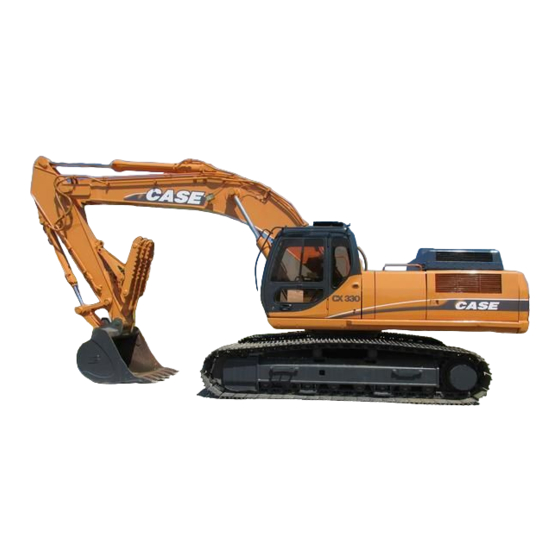
CX330, CX330NLC and CX350 Tier 3 Crawler Excavators
DIVISION/SECTION
1
GENERAL INFORMATION
Safety, general information and standard torque data .....................................1001
General specifications and special torque setting............................................1002
2
ENGINE
Radiator and engine, removal and installation .................................................2001
Engine specifications ............................................................................................. *
Disassembly and assembly of the engine.............................................................. *
3
FUEL SYSTEM
Fuel tank ..........................................................................................................3001
Fuel engine system................................................................................................ *
4
ELECTRICAL SYSTEM
Electrical system, electrical and electronic troubleshooting.............................4001
Inspection and maintenance of batteries and connecting a booster battery....4002
Main and engine electronic control boxes........................................................4003
5
UNDERCARRIAGE
Removal and installation of tracks ...................................................................5001
Rollers..............................................................................................................5003
Sprocket ...........................................................................................................5004
Idler wheel and tension shock absorber ..........................................................5005
6
DRIVE TRAIN
Drive motor and final drive transmission removal and installation ...................6001
Swing reduction gear, removal and installation................................................6003
Swing reduction gear, disassembly and assembly...........................................6004
Travel reduction gear disassembly and assembly ...........................................6005
7
UNDERCARRIAGE HYDRAULICS
8
UPPERSTRUCTURE HYDRAULICS
Depressurising and decontaminating the hydraulic system, use of the
vacuum pump and bleeding the components ..............................................8000
Specifications, troubleshooting, checks and hydraulic pressure settings.........8001
Hydraulic reservoir removal and installation ....................................................8002
Main and pilot pumps, removal and installation ...............................................8003
Main hydraulic control valve, removal and installation .....................................8004
Attachment cylinders, removal and installation ................................................8005
Hydraulic swivel, removal and installation........................................................8006
Pilot blocs, removal and installation .................................................................8007
Swing motor, removal and installation..............................................................8008
Main hydraulic pump, disassembly and assembly ...........................................8010
Main hydraulic control valve, disassembly and assembly ................................8011
Attachment cylinders, disassembly and assembly...........................................8012
Hand control levers, disassembly and assembly .............................................8013
Foot control levers, disassembly and assembly ...............................................8014
Six-solenoid valves, disassembly and assembly..............................................8015
Caution valve, disassembly and assembly.......................................................8016
Hydraulic swivel, disassembly and assembly...................................................8018
Swing motor, disassembly and assembly ........................................................8019
Hydraulic functions...........................................................................................8020
Travel hydraulic motor, disassembly and assembly..........................................8021
Hydraulic component functions ........................................................................8030
Table of Contents
SECTION N°
REFERENCE N°
7-27691EN
9-94170EN
9-94830EN
9-43471EN
9-94180EN
9-43460EN
9-43451EN
9-42910EN
9-42921EN
9-36890EN
9-94790EN
9-43141EN
9-43210EN
9-43221EN
9-43151EN
9-43501EN
9-94190EN
9-43230EN
9-94840EN
9-43261EN
9-43251EN
9-43390EN
9-43400EN
9-43200EN
9-94850EN
9-43551EN
9-94760EN
9-94630EN
7-28301EN
9-43361EN
9-94770EN
9-43190EN
9-43441EN
9-94200EN
9-43161EN
9-94210EN

Advertisement

loading

Summary of Contents for Case CX330NLC

  • Page 1 CX330, CX330NLC and CX350 Tier 3 Crawler Excavators Table of Contents DIVISION/SECTION SECTION N° REFERENCE N° GENERAL INFORMATION Safety, general information and standard torque data ........1001 7-27691EN General specifications and special torque setting..........1002 9-94170EN ENGINE Radiator and engine, removal and installation ..........2001 9-94830EN Engine specifications .....................
  • Page 2 DIVISION/SECTION SECTION N° REFERENCE N° UPPERSTRUCTURE Upperstructure, turntable and counterweight...........9002 9-43411EN Boom, dipper and bucket .................9003 9-43421EN Seat and seat belt ....................9004 9-40960EN Cab and cab equipment...................9005 9-94800EN Air conditioning troubleshooting ...............9006 7-xxxxxFR Air conditioning unit disassembly and assembly..........9007 9-94640EN Air conditioning servicing .................9008 7-xxxxxFR Air conditioning components................9009...
  • Page 3 Section 1001 SAFETY, GENERAL INFORMATION AND TORQUE SPECIFICATIONS Lep 7-27691EN...
  • Page 4 1001-2 TABLE OF CONTENTS GENERAL INFORMATION ............................3 SAFETY..................................4 STANDARD TORQUE DATA FOR CAP SCREWS AND NUTS................6 WARNING : This symbol is used in this manual to indicate important safety messages. Whenever you see this symbol, carefully read the message that follows, as there is a risk of serious injury. Lep 7-27691EN Issued 02-06...
  • Page 5 Parts Catalog for the correct part Bearings number of the genuine Case replacement items. Failures due to the use of other than genuine Case Check bearings for easy action. If bearings have a replacement parts are not covered by warranty.
  • Page 6 Operator’s and Service Manuals may be obtained from WARNING: Read the operator’s manual to your Case dealer. familiarize yourself with the correct control functions. WARNING: If you wear clothing that is too...
  • Page 7 1001-5 WARNING: When servicing or repairing the WARNING: Use insulated gloves or mittens machine, keep the shop floor and operator’s when working with hot parts. compartment and steps free of oil, water, grease, tools, etc. Use an oil absorbing material and/or shop cloths as required. Use WARNING: Lower all attachments to the safe practices at all times.
  • Page 8 1001-6 STANDARD TORQUE DATA FOR CAP SCREWS AND NUTS Tightening of cap screws, nuts Tighten alternately so that tightening torque can be applied evenly. The numbers in the figure below indicate the order of tightening. JS00481A Cap screws which have had Loctite used (white residue remains after removal) should be cleaned with loght oil or suitable cleaning solvent and dried.
  • Page 9 Section 1002 SPECIFICATIONS AND SPECIAL TORQUE SETTINGS Lep 9-94170EN...
  • Page 10 1002-2 TABLE OF CONTENTS WARNING: This symbol is used in this manual to indicate important safety messages. Whenever you see this symbol, carefully read the message which follows. Your safety depends on it. TYPE, SERIAL NUMBER AND YEAR OF MANUFACTURE OF THE MACHINE ............ 3 FLUIDS AND LUBRICANTS .............................
  • Page 11 For all part orders, request for information or assistance, always specify the type and the serial number of the machine to your Case dealer. Fill in the following lines with the required information: Type, serial number, year of manufacture of the machine and the serial numbers of the hydraulic and mechanical components.
  • Page 12 CASE/AKCELA: HYDRAULIC EXCAVATOR FLUID (MS 1230. ISO VG 46. DIN 51524 PART 2 HV) Hot climates: 0°C to +50°C (32° to 122° F) CASE/AKCELA: AW HYDRAULIC FLUID 68 HV (MS 1216. ISO VG 68. DIN 51524 PART 3 CATEGORY HVLP) Cold climates: -25°C to +20°C (-13° to 68° F) CASE/AKCELA: AW HYDRAULIC FLUID 32 (MS 1216.
  • Page 13 This oil ensures proper lubrication of your engine for all operating conditions. If you are unable to procure the CASE No. 1 Multiper- formance or Performance engine oil, use the corre- sponding oil from the API/CG/CF category.
  • Page 14 Using fuels other than those recommended can damage the fuel injection pump, the injector and other parts of the fuel supply system and the engine. CASE disowns any responsibility concerning this kind of damage, which is not covered by the guarantee. To avoid any damage to the engine fuel supply system, you are recommended to take the following safety messages into account: Some fuel suppliers mix used engine oil with diesel fuel.
  • Page 15 Anti-freeze/Anti-corrosion Use anti-freeze in all seasons to protect the cooling system from corrosion and all risk of freezing. CASE/AKCELA: PREMIUM ANTI-FREEZE (MS 1710) For areas where the temperature goes down to -38°C, mix 50/50 with water. IMPORTANT : Do not mix products of a different origin or brand. The same product must be used when topping up the system.
  • Page 16   BUY NOW  Then Instant Download  the Complete Manual  Thank you very much! ...

This manual is also suitable for:

Cx330Cx350