Table of Contents
Advertisement
Quick Links
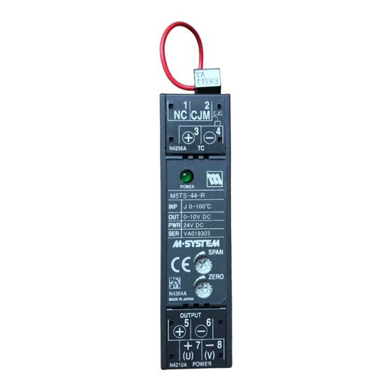
Super-mini Terminal Block Signal Conditioners M5-UNIT
THERMOCOUPLE TRANSMITTER
Functions & Features
• Accepts direct input from a thermocouple and provides a
standard process signal
• Linearization and burnout
• Cold junction compensation
• Fast response type available
• High-density mounting
• Power LED
• CE marking for 24 V power
25 (.98)
97
(3.82)
41 (1.61)
mm (inch)
M5TS-❑❑-❑❑
ORDERING INFORMATION
Specify a code from below for each [1] through [4].
• Code number: M5TS-[1][2]-[3][4]
(e.g. M5TS-2A-R/K/BL/Q)
Specify variables.
• Temperature range (e.g. 0 – 800°C)
• Special output range (For codes Z & 0)
• Specify the specification for option code /Q
(e.g. /C01 /V01)
[1] INPUT THERMOCOUPLE
1: (PR) (Usable Range 0 to 1760°C, 32 to 3200°F)
2: K (CA) (Usable range -270 to +1370°C, -454 to +2498°F)
3: E (CRC) (Usable range -270 to +1000°C, -454 to +1832°F)
4: J (IC) (Usable range -210 to +1200°C, -346 to +2192°F)
5: T (CC) (Usable range -270 to +400°C, -454 to +752°F)
6: B (RH) (Usable range 0 to 1820°C, 32 to 3308°F)
7: R (Usable range -50 to +1760°C, -58 to +3200°F)
8: S (Usable range -50 to +1760°C, -58 to +3200°F)
N: N (Usable range -270 to +1300°C, -454 to +2372°F)
0: Specify
[2] OUTPUT
Current
A: 4 – 20 mA DC (Load resistance 550 Ω max.)
D: 0 – 20 mA DC (Load resistance 550 Ω max.)
SEN TRONIC
AG
Produkte, Support und Service
Z: Specify current (See OUTPUT SPECIFICATIONS)
Voltage
1: 0 – 10 mV DC (Load resistance 100 kΩ min.)
(CE not available)
2: 0 – 100 mV DC (Load resistance 100 kΩ min.)
(CE not available)
3: 0 – 1 V DC (Load resistance 100 Ω min.)
4: 0 – 10 V DC (Load resistance 1000 Ω min.)
5: 0 – 5 V DC (Load resistance 500 Ω min.)
6: 1 – 5 V DC (Load resistance 500 Ω min.)
1W: -10 – +10 mV DC (Load resistance 100 kΩ min.)
(CE not available)
2W: -100 – +100 mV DC (Load resistance 100 kΩ min.)
(CE not available)
3W: -1 – +1 V DC (Load resistance 800 Ω min.)
4W: -10 – +10 V DC (Load resistance 8000 Ω min.)
5W: -5 – +5 V DC (Load resistance 4000 Ω min.)
0: Specify voltage (See OUTPUT SPECIFICATIONS)
01: Specify voltage (See OUTPUT SPECIFICATIONS)
(CE not available)
[3] POWER INPUT
AC Power
M: 85 – 264 V AC (Operational voltage range 85 – 264 V,
47 –66 Hz)
(CE not available)
DC Power
R: 24 V DC
(Operational voltage range 24 V ±10 %, ripple 10 %p-p max.)
[4] OPTIONS (multiple selections)
RESPONSE TIME (0 – 90 %)
blank: Standard (≤ 0.5 sec.)
/K: Fast Response (Approx. 25 msec.)
BURNOUT
blank: Upscale burnout
/BL: Downscale burnout
/BN: No burnout
OTHER OPTIONS
blank: none
/Q: Option other than the above (specify the specification)
OPTION SPECIFICATIONS OF /Q (multiple selections)
COATING (For the detail, refer to M-system's web site.)
/C01: Silicone coating
/C02: Polyurethane coating
/C03: Rubber coating
ADJUSTMENT
/V01: Multi-turn fine adjuster
Rugghölzli 2
Tel. +41 (0)56 222 38 18
CH - 5453 Busslingen
Fax +41 (0)56 222 10 12
MODEL: M5TS
mailbox@sentronic.com
www.sentronic.com
Advertisement
Table of Contents

Related Manuals for M-system M5TS Series


Summary of Contents for M-system M5TS Series
- Page 1 6: B (RH) (Usable range 0 to 1820°C, 32 to 3308°F) OPTION SPECIFICATIONS OF /Q (multiple selections) 7: R (Usable range -50 to +1760°C, -58 to +3200°F) COATING (For the detail, refer to M-system's web site.) 8: S (Usable range -50 to +1760°C, -58 to +3200°F) /C01: Silicone coating N: N (Usable range -270 to +1300°C, -454 to +2372°F)
-
Page 2: General Specifications
0°C. Consult Dielectric strength (input to output to power to ground) M-System. DC powered: 2000 V AC @1 minute Note 2: Consult M-System for the range out of the above AC powered: 1500 V AC @1 minute list. STANDARDS & APPROVALS... -
Page 3: Front View
MODEL: M5TS FRONT VIEW Power LED Span Adj. Zero Adj. DIMENSIONS unit: mm (inch) 7.3 (.29) 8–M3.5 SCREW DIN RAIL 35mm wide 25 (.98) 41 (1.61) [3.3 (.13)] • When mounting, no extra space is needed between units. TERMINAL ASSIGNMENTS unit: mm (inch) CJC Sensor SEN TRONIC Rugghölzli 2... - Page 4 MODEL: M5TS SCHEMATIC CIRCUITRY & CONNECTION DIAGRAM Burnout comp. leadwire Isolation Low Drift Output Linearizer Amplifier Amplifier Driver OUTPUT – – metal leg – POWER LED U(+) Cold Junction SENSOR POWER Compensation V(–) model: CJM *Deleted with B thermocouple Specifications are subject to change without notice. SEN TRONIC Rugghölzli 2 Tel.
-
Page 5: Component Identification
BEFORE USE ..40V or less between lines. Recommended M-System mod- el: MDP-D24. Thank you for choosing M-System. Before use, please check contents of the package you received as outlined below. ■ AND ..If you have any problems or questions with the product, •... -
Page 6: Terminal Connections
M-System’s sole liability, and purchaser’s exclusive remedies, under this warranty are, at M-System’s option, the repair, replacement or refund of the purchase price of any M-System product which is defective under the terms of this warranty. To submit a claim under this warranty, the purchaser must return, at its expense, the defective M-System product to the below address together with a copy of its original sales invoice.
Need help?
Do you have a question about the M5TS Series and is the answer not in the manual?
Questions and answers