Advertisement
Quick Links
INSTRUCTION MANUAL
ANALOG BACKUP STATION
(with bargraph/digital indicator)
BEFORE USE ....
Thank you for choosing M-System. Before use, please check
contents of the package you received as outlined below.
If you have any problems or questions with the product,
please contact M-System's Sales Office or representatives.
■ PACKAGE INCLUDES:
Analog backup station .................................................. (1)
■ MODEL NO.
Confirm Model No. marking on the product to be exactly
what you ordered.
■ INSTRUCTION MANUAL
This manual describes necessary points of caution when
you use this product, including installation, connection and
basic maintenance procedures.
POINTS OF CAUTION
■ POWER INPUT RATING & OPERATIONAL RANGE
• Locate the power input rating marked on the product and
confirm its operational range as indicated below:
100 – 240V AC rating: 85 – 264V, 50/60 Hz, approx. 4 – 6VA
24V DC rating: 24V ±10%, approx. 3.5W
• Power fuse: A power fuse of the rating as shown below is
incorporated for safety. However, DO NOT replace it by
the user.
AC rating: T 0.25A 250V
DC rating: T 0.5A 250V
■ ENVIRONMENT
• Indoor use
• If the unit's environmental protection is compromised
(e.g. when multiple units are to be mounted side by side)
when heavy dust or metal particles are present in the air,
install them inside an enclosure with a proper ventilation.
• Do not install the unit where it is subjected to continuous
vibration. Do not apply physical impact to the unit.
• Environmental temperature must be within -5 to +55°C
(23 to 131°F) with relative humidity within 30 to 90% RH
in order to ensure adequate life span and operation.
■ REQUIREMENTS TO ENSURE IP 65
• Observe the designated panel cutout size (45 × 92 mm).
• Single mounting only. IP 65 is not ensured when the units
are clustered side by side.
• The watertight packing included in the product package
must be placed behind the front cover.
• Both mounting brackets must be fastened tightly until
they hit the panel.
• Confirm visually that the packing is not contorted or ex-
cessively run off the edge after installation.
■ WIRING
• Do not install cables (power supply, input and output)
close to noise sources (high frequency line, etc.).
• Do not bind these cables together with those in which
noises are present. Do not install them in the same duct.
MODEL
■ AND ....
The unit is designed to function as soon as power is sup-
plied, however, a warm up for 20 minutes is required for sat-
isfying complete performance described in the data sheet.
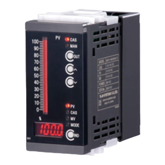
COMPONENT IDENTIFICATION
A
PV
50
10 0
CA S
90
MA N
40
80
OU T
70
30
60
50
20
40
30
10
20
10
0
PV
0
CA S
m
%
MV
MO DE
IND
%
Scale Plate
Pull up the part 'A' when replacing the scale plate.
■ FRONT PANEL CONFIGURATION
Tag Plate
55-segment
LED Bargraph
PV
50
100
90
40
80
70
30
60
50
20
40
30
10
20
10
0
0
Digital Display
m
%
%
ABF3
ABF3
Brackets
Terminal Block
Cover
Body
CAS Output LED
(ON at CAS Mode)
MAN Output LED
(ON at Manual Mode)
CAS-MAN Selector
CAS
MAN
MAN Control Button (UP)
OUT
MAN Control Button (DOWN)
PV LED
CAS LED
MV LED
PV
CAS
MODE LED
MV
MODE
Digital Display
IND
Selector
EM-2614 Rev.5
P. 1 / 5
Advertisement

Related Manuals for M-system ABF3


Summary of Contents for M-system ABF3
- Page 1 The unit is designed to function as soon as power is sup- plied, however, a warm up for 20 minutes is required for sat- Thank you for choosing M-System. Before use, please check isfying complete performance described in the data sheet.
-
Page 2: Installation
ABF3 INSTALLATION ■ PANEL CUTOUT unit: mm • Single Mounting (ingress protection) • Clustered Mounting (no ingress protection) + 0.6 – 0 Panel thickness: 1.6 – 8.0 mm Panel thickness: 1.6 – 8.0 mm L = (45.5 + 48 x (N – 1)) –0... - Page 3 ABF3 ■ EXTERNAL DIMENSIONS unit: mm (inch) MOUNTING BRACKET TERMINAL BLOCK COVER 4–M3 SCREW 20–M3 SCREW TERMINAL MODE 10 20 2 (.08) 48 (1.89) 45 (1.77) 86 (3.39) 12.5 (.49) 98.5 (3.88) • When mounting, no extra space is needed between units.
-
Page 4: Setting Procedure
ABF3 SETTING PROCEDURE ■ SWITCHING BETWEEN DIGITAL DISPLAY / SETTING MODES LED ON Display Selector MODE (red) (red) (red) (red) MODE (green) (green) (green) (green) ■ SETTING MANUAL OUTPUT (CAS Mode to MAN Mode) LED ON CAS-MAN Selector MAN Control Buttons... - Page 5 M-System’s option, the repair, replacement or refund of the purchase price of any M-System product which is defective under the terms of this warranty. To submit a claim under this warranty, the purchaser must return, at its expense, the defective M-System product to the below address together with a copy of its original sales invoice.
Need help?
Do you have a question about the ABF3 and is the answer not in the manual?
Questions and answers