
Related Manuals for FRAMOS D455e


Summary of Contents for FRAMOS D455e
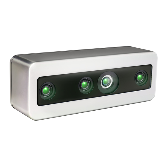
- Page 1 FRAMOS Industrial Depth Camera D400e Series USER MANUAL Version 1.6.0 from 2021-10-15 www.framos.com...
-
Page 2: Table Of Contents
4.3.2 Power M8 connector, A-Coded, Male ....................21 Thermal Control ............................ 22 Storage and Operating Conditions ....................... 22 Power Consumption ..........................22 Depth Camera Depth Origin Reference ....................23 FRAMOS Industrial Depth Camera D400e Series - User Manual Version 1.6.0 from 2021-10-15 2 of 64... - Page 3 Minimum-Z Depth ..........................40 Depth Quality Specifications ......................... 41 Depth Camera Functions ........................42 Color Camera Functions ........................42 Inertial Measurement Unit Streams ...................... 43 FRAMOS Industrial Depth Camera D400e Series - User Manual Version 1.6.0 from 2021-10-15 3 of 64...
- Page 4 10.1.2 Manage Camera Calibration Tables ....................57 10.2 Intel® RealSense™ Software Development Kit 2.0 ................58 Troubleshooting ......................59 Regulatory Compliance ....................60 Accessories ........................62 References ........................63 Revision History......................64 FRAMOS Industrial Depth Camera D400e Series - User Manual Version 1.6.0 from 2021-10-15 4 of 64...
- Page 5 Figure 6 – Depth Camera D455e Depth Origin Reference ............24 Figure 7 – FRAMOS D400e Module Components Overview ............25 Figure 8 – Connecting Interposer Cables to FRAMOS D4 Visual Processing Board ....26 Figure 9 – FRAMOS D4 Visual Processing Board Ethernet Connector ........27 Figure 10 –...
- Page 6 Table 30 – Example of Possible Streams on Gigabit Ethernet Network ........39 Table 31 – Depth FOV ......................40 Table 32 – Minimum-Z Depth ....................40 Table 33 – Depth Quality Specifications for FRAMOS D400e Series Camera ......41 Table 34 – Depth Camera Functions ..................42 Table 35 – Color Camera Functions..................43 Table 36 –...
- Page 7 Image Signal Processor Link-Local Address Network Interface Card Output Physical Layer Power Over Ethernet Relative Humidity Return Material Authorization Software Development Kit To Be Determined FRAMOS Industrial Depth Camera D400e Series - User Manual Version 1.6.0 from 2021-10-15 7 of 64...
-
Page 8: Description And Features
The D400e Series are compatible with the Cross-platform SDK for Intel® RealSense™ devices, enabling multiple programming languages, wrappers, sample code and tools. D435e and D455e camera models, featuring global shutter, wide field of view sensors, are especially suitable for applications with fast motion. -
Page 9: Introduction
Introduction 2.1 Purpose of this Document This document contains the specifications and the design–in details for the FRAMOS Industrial Depth Camera D400e Series. This document provides information necessary to understand and implement the camera system. 2.2 Terminology Term Description 6DOF Six degrees of freedom (6DoF) refers to the freedom of movement of a rigid body in three-dimensional space. -
Page 10: Stereo Vision Depth Technology Overview
2.3 Stereo Vision Depth Technology Overview The FRAMOS Industrial Depth Camera D400e Series use stereo vision to calculate depth. The stereo vision implementation consists of a left imager, right imager, and an optional infrared projector. The infrared projector projects non-visible static IR pattern to improve depth accuracy in scenes with low texture. -
Page 11: Component Overview
3.1 Stereo Depth Module The stereo depth module used in the D435e camera is the Intel® RealSense™ D430, D415e implements Intel® RealSense™ D410 depth module, while D455e implements Intel® RealSense™ D450 depth module. Properties of the Intel® RealSense™ depth modules are as follows:... -
Page 12: Left And Right Imagers
None Focus Fixed Shutter Type Global Shutter Imager Field of View H:90.0° / V:65.0° / D:98.0° Distortion <=1.5% Table 7 – D450 Imager Properties FRAMOS Industrial Depth Camera D400e Series - User Manual Version 1.6.0 from 2021-10-15 12 of 64... -
Page 13: Infrared Projector
Class 1, IEC 60825-1:2007 Edition 2, IEC Laser Compliance 60825-1:2014 Edition 3 Field of Projection H:64°±3° / V:41°±3° / D:72°±3° Table 9 – D410 infrared projector properties FRAMOS Industrial Depth Camera D400e Series - User Manual Version 1.6.0 from 2021-10-15 13 of 64... -
Page 14: Color Sensor
Focus Fixed Shutter Type Global Shutter Imager Field of View H:90.0° / V:65.0° / D:98.0° Distortion <=1.5% Table 11 – D455e Color Sensor Properties FRAMOS Industrial Depth Camera D400e Series - User Manual Version 1.6.0 from 2021-10-15 14 of 64... -
Page 15: Inertial Measurement Unit
3.5 Inertial Measurement Unit Inertial Measurement Unit (IMU) contains sensors which allow measurement of both directional movement and rotation. FRAMOS D400e depth cameras generate and transmit the gyro and accelerometer samples independently, as the inertial sensors exhibit different FPS rates (200/400Hz for gyro, 63/250Hz for accelerometer). -
Page 16: Table 14 - Framos D4 Visual Processing Board Key Components
Implements the physical layer of the Ethernet Gigabit Ethernet Transceiver (Ethernet PHY) Table 14 – FRAMOS D4 Visual Processing Board Key Components FRAMOS D4 Visual Processing Board Dimensions Module Dimensions (mm) X=93mm / Y=40mm / Z=15mm Table 15 –... -
Page 17: Framos Depth Camera D400E Series
250 grams 395 grams Protection Glass AR coating, scratch resistant (6H) Housing material Aluminum, anodized Table 16 – FRAMOS Depth Camera D400e Series Properties FRAMOS Industrial Depth Camera D400e Series - User Manual Version 1.6.0 from 2021-10-15 17 of 64... -
Page 18: Mechanical Dimensions
4.2 Mechanical Dimensions Front View D435e Front View D415e Front View D455e FRAMOS Industrial Depth Camera D400e Series - User Manual Version 1.6.0 from 2021-10-15 18 of 64... -
Page 19: Table 17 - D400E Series Camera Dimensions
Side View D435e/D415e Side View D455e Back View D435e/D415e Back View D455e Table 17 – D400e Series Camera Dimensions FRAMOS Industrial Depth Camera D400e Series - User Manual Version 1.6.0 from 2021-10-15 19 of 64... -
Page 20: Physical Interfaces
4.3 Physical Interfaces FRAMOS D400e series cameras are equipped with two physical interfaces: M12 Ethernet connector for data interface M8 Power connector for power and I/O interfaces 4.3.1 Ethernet M12 connector, X-Coded, Female The Ethernet interface provides configuration access to the camera and is also used for image data transmission. -
Page 21: Power M8 Connector, A-Coded, Male
Figure 2 – Example of connecting M12 to RJ45, T568B termination 4.3.2 Power M8 connector, A-Coded, Male Beside the Ethernet interface for communication and data transmission, FRAMOS D400e series cameras are equipped with M8 connector providing I/O-interface and power input. -
Page 22: Thermal Control
Power via M12 (PoE) 6.9W Table 21 – D400e Series Camera Power Consumption Information: FRAMOS D400e Series Camera is IEEE 802.3af compliant PD (Powered Device) so it requires IEEE 802.3af compliant PSE (Power Sourcing Equipment). FRAMOS Industrial Depth Camera D400e Series - User Manual Version 1.6.0 from 2021-10-15... -
Page 23: Depth Camera Depth Origin Reference
4.7 Depth Camera Depth Origin Reference Figure 4 – Depth Camera D415e Depth Origin Reference Figure 5 – Depth Camera D435e Depth Origin Reference FRAMOS Industrial Depth Camera D400e Series - User Manual Version 1.6.0 from 2021-10-15 23 of 64... -
Page 24: Labels On The Camera
Figure 6 – Depth Camera D455e Depth Origin Reference 4.8 Labels on the Camera The information about camera Product Code and Serial Number is available on camera label: FRAMOS Depth FRAMOS Depth FRAMOS Depth Camera D415e Camera D435e Camera D455e... -
Page 25: Framos Depth Camera D400E Module Variant
FRAMOS Depth Camera D400e Module Variant FRAMOS Depth Camera D400e module variant is a module version of the D400e series camera, providing the same functionality and connectivity without housing. The module variant aims for the easy design-in and integration into compact form factor products. -
Page 26: D400E Module Variant Connectors Pinout
Figure 8 – Connecting Interposer Cables to FRAMOS D4 Visual Processing Board Caution: Care should be taken when connecting RGB and Depth Interposer cables to FRAMOS D4 Visual Processing Board, as the wrong connection, position or orientation, can cause permanent damage to the device. The correct cables position and orientation are shown in the Figure 8. -
Page 27: Ethernet Connector J3
5.2.1 Ethernet Connector J3 Figure 9 – FRAMOS D4 Visual Processing Board Ethernet Connector J3 Pin Description BI_DA+ BI_DA- BI_DD+ BI_DD- BI_DC+ BI_DC- BI_DB+ BI_DB- Table 23 – J3 Pin Assignment FRAMOS Industrial Depth Camera D400e Series - User Manual Version 1.6.0 from 2021-10-15... -
Page 28: Power And Io Connector J6
5.2.2 Power and IO Connector J6 Figure 10 – FRAMOS D4 Visual Processing Board Power and IO Connector J6 Pin Description DC Power supply, 12-24V DC (+/- 10%) Power GND Not connected Not connected Not connected GND for opto-isolated I/O... -
Page 29: Thermal Design Consideration
"Optimum Thermal Conditions" chapter. 5.4 Mechanical Drawings 5.4.1 FRAMOS D4 Visual Processing Board Top and side views and dimensions [mm] for the FRAMOS D4 Visual Processing Board are shown in the image below. Figure 11 – FRAMOS D4 Visual Processing Board Dimensions 5.4.2 Depth Module Interposer... -
Page 30: Depth Module Cable Bracket
Figure 13 – D435e Depth Module Cable Bracket Dimensions Figure 14 – D415e Depth Module Cable Bracket Dimensions Figure 15 – D455e Depth Module Cable Bracket Dimensions 5.4.4 RGB Module Including Cover Figure 16 – RGB Module Including Cover Dimensions 5.4.5 RGB Interconnect... -
Page 31: Optimum Thermal Conditions
Four threaded holes (M3 for D415e/D435e, M4 for D455e) are available on the camera back side to attach the camera to a mounting facility. It is recommended to use thermal paste on the contact surface between the camera and the heatsink for maximum thermal conductivity. -
Page 32: Operating Conditions For Different Temperatures
Power supply: M12, PoE Exposure time: 30 ms Framerate: 30 fps Laser projector power: 360 mW Table 27 – Operating Conditions for Different Temperatures FRAMOS Industrial Depth Camera D400e Series - User Manual Version 1.6.0 from 2021-10-15 32 of 64... - Page 33 Heatsink length: 50 mm Thermal resistance: approx. 2.3 K/W SK 530 100 AL H3 - passive Heatsink length: 100 mm Thermal resistance: approx. 0.38 K/W FRAMOS Industrial Depth Camera D400e Series - User Manual Version 1.6.0 from 2021-10-15 33 of 64...
-
Page 34: Table 28 - Heat Dissipation Elements
H4 - active SK 424 75 ME Heatsink length: 75 mm Cooling fan: Xilence XPF40 Table 28 – Heat Dissipation Elements FRAMOS Industrial Depth Camera D400e Series - User Manual Version 1.6.0 from 2021-10-15 34 of 64... -
Page 35: Maximum Operating Ambient Temperatures
Recommendation: Use metal camera mount to assure optimal heat conductivity (avoid plastic mounts). FRAMOS Industrial Depth Camera D400e Series - User Manual Version 1.6.0 from 2021-10-15 35 of 64... - Page 36 Recommendation: Minimize the resource utilization (i.e. fps, exposure, projector intensity) of the camera, which will positively affect heat generation and longevity of the product. FRAMOS Industrial Depth Camera D400e Series - User Manual Version 1.6.0 from 2021-10-15 36 of 64...
-
Page 37: Mounting And Deployment
100 cNm for these screws. Figure 19 – D400e Series Camera Body Back Side The D455e camera features four robust M4 thread holes for mounting, with stainless steel thread inserts and maximum insertion depth of 5mm. Applied tightening torque for mounting screws should not exceed 100 cNm, to avoid thread damage. -
Page 38: Application Of External Cabling
This should be prevented as it could cause damage to the internal camera wiring. The FRAMOS D400e series camera is supplied with the M8 connector covered with a protective plastic cap. The function of the protective cap is to protect the M8 connector against impurities and moisture in the case the connector is not used, thus keeping it clean and ready for future. -
Page 39: Functional Specification
1280x720 848x480 960x540 848x480 848x480 848x480 1920x1080 640x480 640x480 640x360 640x360 424x240 424x240 Table 30 – Example of Possible Streams on Gigabit Ethernet Network FRAMOS Industrial Depth Camera D400e Series - User Manual Version 1.6.0 from 2021-10-15 39 of 64... -
Page 40: Depth Field Of View (Fov)
Processor D4 provides depth data. D435e D415e D455e Resolution Min-Z (mm) Min-Z (mm) Min-Z (mm) 1280x720 848x480 640x480 640x360 480x270 424x240 Table 32 – Minimum-Z Depth FRAMOS Industrial Depth Camera D400e Series - User Manual Version 1.6.0 from 2021-10-15 40 of 64... -
Page 41: Depth Quality Specifications
8.4 Depth Quality Specifications Set of standard metrics based on accuracy, data validity and temporal stability are used to determine the depth quality. FRAMOS D400e series camera depth quality specifications are the same as the corresponding Intel D400 series camera specifications. Metric... -
Page 42: Depth Camera Functions
Sets the amount of gain applied Gain to the frame if autoexposure is disabled. Sets the amount of hue -180 adjustment applied to the frame. FRAMOS Industrial Depth Camera D400e Series - User Manual Version 1.6.0 from 2021-10-15 42 of 64... -
Page 43: Inertial Measurement Unit Streams
Packet Size values. This reduces the number of packets sent by the camera, thus reducing the packet overhead and workload of the host NIC. FRAMOS Industrial Depth Camera D400e Series - User Manual Version 1.6.0 from 2021-10-15 43 of 64... -
Page 44: Inter Packet Delay
For more information, please refer to document d400e_api_extensions.md (part of the D400e software package). 8.8.4 Inter Cam Sync Mode Enables synchronous streaming of multiple cameras and stream synchronization to an external event. FRAMOS D400e camera provides the following Inter Cam Sync modes: Default Master ... -
Page 45: Output Trigger Enabled
8.8.5 Output Trigger Enabled Output Trigger Enabled feature switches between the synchronization signal VSYNC (described in FRAMOS Industrial Depth Camera D400e Series - External Event Camera Synchronization [Ref-2]) and user controllable output. When enabled VSYNC is selected as M8 Pin 3 driver. VSYNC drives pin in all Inter Cam Sync modes. -
Page 46: Rgb/Stereo Synchronization
8.8.8 RGB/Stereo Synchronization By default, FRAMOS D400e camera operates in the "Default" operating mode, with asynchronous streams from the RGB and Stereo sensor. For explanation on the camera operating modes please... -
Page 47: Syncer Mode
(original librealsense2 syncer implementation) in which the same frame, in certain situations, can be returned in consecutive framesets by "wait_for_frames" call, as shown in Figure 24. FRAMOS Industrial Depth Camera D400e Series - User Manual Version 1.6.0 from 2021-10-15... -
Page 48: Figure 24 - Syncer Default Mode
```cpp rs2::config cfg; //config object cfg.set_syncer_mode(RS2_SYNCER_MODE_WAIT_FRAMESET); ```c rs2_error* e = 0; rs2_config* config = rs2_create_config(&e); check_error(e); rs2_config_set_syncer_mode(config, RS2_SYNCER_MODE_WAIT_FRAMESET, &e); ```python config = rs.config() config.set_syncer_mode(rs.syncer_mode.wait_frameset) FRAMOS Industrial Depth Camera D400e Series - User Manual Version 1.6.0 from 2021-10-15 48 of 64... -
Page 49: Firmware Updates
Ethernet interface. This allows implementing new features and potential bug fixes using the firmware update tool. The UpdateFirmware tool is used to update the firmware on FRAMOS Industrial Depth Cameras. The firmware update file is verified by the tool for compatibility with selected camera before firmware update process is initiated. -
Page 50: Parallel Firmware Update
If there are cameras in the list that are not compatible with firmware update file, the UpdateFirmware tool will simply ignore these cameras and will inform user about incompatibility at the end of the firmware update procedure. FRAMOS Industrial Depth Camera D400e Series - User Manual Version 1.6.0 from 2021-10-15 50 of 64... -
Page 51: Firmware Update Non-Interactive Mode
To perform firmware update on a set of cameras, specify serial numbers of the selected cameras after the "-sn" argument and separate them with comma sign delimiter (no spaces are allowed): FRAMOS Industrial Depth Camera D400e Series - User Manual Version 1.6.0 from 2021-10-15... -
Page 52: Ip Address Conflict
Figure 32. Figure 31 – IP address conflict Figure 32 – IP address conflict when selecting all devices FRAMOS Industrial Depth Camera D400e Series - User Manual Version 1.6.0 from 2021-10-15 52 of 64... -
Page 53: Non-Interactive Mode
If the list contains a camera that is in IP address conflict, the firmware update procedure will be terminated. Figure 33 – IP address conflict, procedure terminated FRAMOS Industrial Depth Camera D400e Series - User Manual Version 1.6.0 from 2021-10-15 53 of 64... -
Page 54: Software
D400e Series camera to be used by tools based on the Intel® RealSense™ SDK 2.0. 10.1.1 Set IP Configuration ConfigureIP tool is used to configure the IP address of a FRAMOS Industrial Depth Camera. Supported IP configurations are: Persistent IP - fixed IP address which is stored in camera non-volatile memory ... -
Page 55: Figure 34 - Tool Configureip Part 1
Persistent IP configuration, there is a possibility of IP address conflict between two or more cameras. If IP address conflict is detected, the ConfigureIP tool will display a warning message. FRAMOS Industrial Depth Camera D400e Series - User Manual Version 1.6.0 from 2021-10-15... -
Page 56: Figure 36 - Ip Address Conflict Warning Message
To verify if the device has DHCP protocol enabled: Figure 38 – Verification of status of DHCP protocol To verify if the device has persistent IP address enabled: FRAMOS Industrial Depth Camera D400e Series - User Manual Version 1.6.0 from 2021-10-15 56 of 64... -
Page 57: Manage Camera Calibration Tables
Figure 39 – Verification of status of persistent IP address 10.1.2 Manage Camera Calibration Tables CalibrationTables tool is used to manage calibration tables on FRAMOS Industrial Depth Camera D400e Series. Following actions are supported: Read calibration tables from device ... -
Page 58: Intel® Realsense™ Software Development Kit 2.0
10.2 Intel® RealSense™ Software Development Kit 2.0 FRAMOS provides a modified version of the SDK 2.0, which includes a wrapper of the Camera Suite as described above. The modified version of the SDK 2.0 can be downloaded here: https://www.framos.com/en/industrial-depth-cameras The SDK at a minimum includes: Intel®... -
Page 59: Troubleshooting
Troubleshooting FRAMOS For troubleshooting problems related to FRAMOS D400e Series Camera please refer to RealSense Cameras Knowledge Base [Ref-9]. FRAMOS Industrial Depth Camera D400e Series - User Manual Version 1.6.0 from 2021-10-15 59 of 64... -
Page 60: Regulatory Compliance
No magnifying optical elements, such as eye loupes and magnifiers, are allowed. Do not try to update camera firmware that is not officially released for specific camera module and revision. FRAMOS Industrial Depth Camera D400e Series - User Manual Version 1.6.0 from 2021-10-15 60 of 64... - Page 61 For more information, contact the local waste collection center or your point of purchase of this product. Other Certifications Shock DIN EN 60068-2-27 Vibration DIN EN 60068-2-6, DIN EN 60068-2-64 FRAMOS Industrial Depth Camera D400e Series - User Manual Version 1.6.0 from 2021-10-15 61 of 64...
-
Page 62: Accessories
Sensor/actuator cable - SAC-8P- 1,5-PUR/M 8FS SH – 1404147: https://www.phoenixcontact.com/online/portal/pi?uri=pxc-oc- itemdetail:pid=1404147&library=pien&tab=1 M8 Sensor/actuator cable - SAC-8P- 1,5-PUR/M 8FR – 1404191: https://www.phoenixcontact.com/online/portal/us/?uri=pxc-oc- itemdetail:pid=1404191&library=usen&pcck=P-18-01-01&tab=1&selectedCategory=ALL FRAMOS Industrial Depth Camera D400e Series - User Manual Version 1.6.0 from 2021-10-15 62 of 64... -
Page 63: References
FRAMOS GmbH. FRAMOS Industrial Depth Camera D400e Series - Multi-Camera Synchronization, FRAMOS GmbH. FRAMOS Industrial Depth Camera D400e Series - Tuning System For Best Performance, FRAMOS GmbH. Best-Known-Methods for Tuning Intel® RealSense™ D400 Depth Cameras for Best Performance v2.0, Intel RealSense. -
Page 64: Revision History
“RGB/Stereo Synchronization”; Updated chapter “Firmware Updates”; Updated chapter “Software” Table 37 – Revision History This document replaces and supersedes the user manual "FRAMOS Industrial Depth NOTE: Camera D435e" v1.1.0. FRAMOS Industrial Depth Camera D400e Series - User Manual Version 1.6.0 from 2021-10-15...
Need help?
Do you have a question about the D455e and is the answer not in the manual?
Questions and answers