Acom 700S Operating Manual
Hf + 6 m linear amplifier
Hide thumbs
Also See for 700S:
- Operating manual (11 pages) ,
- User manual (52 pages) ,
- User manual (92 pages)
Table of Contents
Advertisement
Quick Links
Advertisement
Table of Contents

Related Manuals for Acom 700S


Summary of Contents for Acom 700S
- Page 1 OPERATING MANUAL...
- Page 2 ACOM Ltd. Sofia-Bozhurishte Economic Zone 6 Valeri Petrov str. 2227 Bozhurishte, Bulgaria phone: +359 2 920 97 80 fax: +359 2 920 96 56 e-mail: acom@acom-bg.com www.acom-bg.com December 2019 Printed in Bulgaria...
-
Page 3: Table Of Contents
TABLE OF CONTENTS GENERAL INFORMATION .........................4 1-1. Inroduction and description .......................4 1-2. Owner assistance ........................4 1-3. Equipment supplied and options ....................4 1-4. Features ............................4 1-5. Safety considerations, explicit definitions .................5 INSTALLATION ............................6 2-1. Unpacking and Initial Inspection ....................6 2-2. Amplifier operating location selection; cooling................7 2-3. -
Page 4: General Information
If technical or operating assistance is needed, please contact your local dealer first. In the unlikely case of you needing further information, you may get in touch with ACOM via: fax (+ 359 2 920 96 56), telephone (+359 2 9209780), e-mail (acom@acom-bg.com, acom@mail.orbitel.bg) or by post (6 Valeri Petrov str.,Bozhurishte 2227,Bulgaria). -
Page 5: Safety Considerations, Explicit Definitions
FCC regulations. This operating manual contains precautions, cautions, and warnings that MUST BE CОMPLIED TO by the user to ensure safe operation and maintaining of the ACOM 700S amplifier in a safe working condition. -
Page 6: Installation
W A R N I N G Do not undertake repairs or changes in hardware or firmware of your ACOM 700S amplifier. Doing so will endanger your or others‘ health or life, or damage the amplifier and the equipment connected to it. Such repairs or changes... -
Page 7: Amplifier Operating Location Selection; Cooling
The ACOM 700S is forced air cooled. Locate the amplifier so that there are no objects or other devices closer than 10cm (4”). The exhaust air can reach 65ºC (150ºF) and if the surrounding devices are sensitive to heating from outside or use forced air cooling themselves, increase the distances accordingly. - Page 8 a) GND stud - First connect the grounding stud of the amplifier (located on the rear panel and marked GND – Fig. 2-1) to the grounding system of the shack. b) KEY-IN jack - amplifier input for receive/transmit control from the transceiver. The transceiver switches the amplifier from receive mode into transmit mode (RX/TX) by grounding of the KEY-IN input.
- Page 9 The transceiver manufacturers give different names to this input, for example: TX-INHIBIT, MUTE, LINEAR, and others. Check the manual of your transceiver. Approach your dealer for details. If your transceiver has no such input, do not worry – ACOM 700S will operate normally with KEY-OUT unconnected.
-
Page 10: Installing Options And Connecting To External Devices, Computer, Etc
2-1 below and the respective menu in S. 5-3, table 5-1 and Fig. 5-3). Most of the modern transceivers can be connected by CAT to the ACOM 700S. This will allow the amplifier to track the transceiver frequency without any transmission and change the bands automatically when in Operate mode. -
Page 11: Powering And Operation
Table 2-2 RS 232 PIN NAME DESCRIPTION SPECIFICATIONS interface Not connected Transmitted Data RS232 level output Received Data RS232 level input Not connected Ground 0 Volt Remote Power On RS232 level input Not connected Remote Power On RS232 level input Not connected Rear panel view... -
Page 12: Initial Turning On
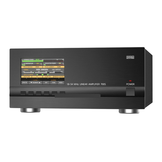
Fig. 3-1 Front panel c) 6 functional buttons keypad for manual (local) control of the amplifier. The function of each button is indicated on the display above it. Depending on the displayed menu, the buttons may have different functions. d) A color display showing the operating information. Initial turning on 3-3. - Page 13 Fig. 3-2 Basic screen b) Operating values and alarm messages area. Any two operating values selected in the AMP MEASURE menu (S. 5-1) will be shown here. The alarm messages (either WARNING or SOFT FAULT) appear on yellow background on the same area and are flashing frequently in order to attract the operator’s attention (Fig.
-
Page 14: Control System - Buttons And Menus
Control system – buttons and menus 3-5. The OPR/STB and the BAND buttons are used for manual (local) control of the (Fig. 3-2): the left-most button OPR/STB switches over the amplifier between Operate and Stand-by modes; the next two buttons – BAND up and down arrows - change the frequency bands in ascending or descending order;... - Page 15 check the good working order of the coaxial cables, connectors, and feed lines from the transceiver antenna jack through the amplifier, the antenna switch or external tuner (if there is one) to the BALUN transformer, and the antenna itself (S. 2-3(e)). If the power and SWR are as expected, transmit again and while watching the power and the SWR readings, increase transceiver power gradually from minimum to maximum (but not more than 200W in order to not overload the RF by-pass circuit of the amplifier).
- Page 16 Upon reaching 700W forward power check the following parameters (continuous carrier operation): the reflected power must not exceed ~78W (for SWR 2:1) or better still to be below 28W (for SWR 1.5:1); PA DC CURRENT must be between 23 and 30A; it is normal that the current varies within these limits when changing operating frequency and antenna impedance;...
-
Page 17: Amplifier Operation
improve the RF grounding system: use the shortest and widest possible metal strips for the connections to ground and between the different gear in the shack; connect one or more counterpoises (sized for the problematic band) to the feeder shield at the point, where it enters the building, and the same point - with the possibly shortest and widest connections - to the grounding system: this is a very efficient measure, in particular if the shack is located on a high floor above ground;... -
Page 18: Band Change, Standard And Expanded Frequency Coverage
C A U T I O N In order to provide time for the relays to switch safely from receive to transmit, the transceiver should provide a dead time i.e. must “notify” the amplifier in due time by grounding the control KEY IN input not later than 10ms before feeding drive power toward the amplifier RF input. -
Page 19: Operation With An External Antenna Tuner
Operation with an external antenna tuner At antenna SWR over 1.5:1, it is advisable you use an external tuner. The ACOM 04AT Remote Automatic Antenna Tuner is designed to work with the ACOM 700S. Use of other antenna tuners is not recommended. -
Page 20: Menus - Settings And Options
At the second level (SOFT FAULT) the amplifier reverts to Stand-by mode for four seconds or permanently depending on whether the “AUTO OPERATE” option had been activated. A respective message is shown on the screen, for example “Excessive Reflected Power”, “Excessive Drain Current”, and others, as well as with a sound alarm (unless the sound had not been muted –... -
Page 21: Menu "Measurements In The Amplifier" - Amp Measure
Fig. 5 - MENU SELECTION 5-1. Menu „Amplifier measurements” – AMP MEASURE The menu AMP MEASURE (Fig. 5-1) is accessible from the MENU SELECTION screen (Fig. 5) in all modes. 11 parameter values be observed continuously. Fig. 5-1 Menu “Amplifier measurements” – AMP MEASURE Two identical lists appear on the left and the right halves of the screen, each one containing the same 11 values. -
Page 22: Menu "Service Functions In The Amplifier" - Amp Service
Any value can be selected in each screen half. Using buttons ITEM1 and ITEM2 (up and down) select the desired values. The two slected values will be shown continuously on the basic screen (S.3-2 (b), Fig. 3-2) - after leaving this menu (EXIT button). 5-2. - Page 23 If the amplifier CAT port is connected either to the transceiver BCD Band Data or Band Voltage output, select the respective interface type and push EXIT. The other items and values will not be taken into account If the CAT cable is plugged into the transceiver’s serial port, select the interface and command set according to Table 5-1.
-
Page 24: Menu "User Preferences
If entered here, a call sign (or another text) will be included in any Fault Log file generated by the amplifier. The call sign (or another text) will not replace ACOM 700S logo on the startup screen. Use the SELECT button to select the character position. The ITEM button changes the characters. -
Page 25: Faults Log
or involuntary switching to Operate mode. While locked, an attempt for entering Operate mode will result in a message: “OPERATE MODE IS LOCKED” The other preference items need no explanation. 5-5. FAULTS LOG This function reads on the screen the information stored in the memory about the last 28 HARD FAULT protection trips (Fig.5-5). -
Page 26: Remote Control
Fig. 5-6 Menu: RESTORE DEFAULT SETTINGS 6. REMOTE CONTROL 6-1. General information The ACOM 700S may be controlled remotely by the RS232 port. The ACOM 700S RS232 interface protocol is available on www.acom-bg.com. 7. MAINTENANCE W A R N I N G HIGH VOLTAGE! -
Page 27: Replacement Of Fuses
ACOM 700S has one air filter that is accessible from the rear - see Fig. 2.1. The filter is contained in an externally mounted plastic enclosure. The cover of the enclosure, together with the filter itself, is removed by gently pulling it away from the amplifier. -
Page 28: Using The Fault Codes (Signatures) For Diagnostics
When ACOM issues a new firmware version, the user can upload it in the amplifier after he checks the compatibility – see the note above. When compatibility is confirmed a return to an earlier version is also possible. -
Page 29: Functions
* Extensions or changes of the frequency coverage are possible on request. ** Please refer the applicable region bandplans and laws for specific allocations and limitations. b) Rated output power: 700W +/-0.5dB, PEP or continuous carrier. c) Intermodulation distortions (IM3): better than 31dB below the rated PEP. d) Harmonic and parasitic emissions output suppression: better than 60dB (65dB typically). -
Page 30: Storage And Shipment
ACOM 700S. Further, this Operating Manual is provided “as is” and ACOM shall not be liable for possible errors contained herein.
Need help?
Do you have a question about the 700S and is the answer not in the manual?
Questions and answers