Advertisement
Table of Contents
- 1 Table of Contents
- 2 Introduction
- 3 Product Overview
- 4 General Specifications
- 5 Dimensions
- 6 General Wiring Diagram
- 7 Modular System
- 8 Choosing Part Numbers for the Bill Validator
- 9 Installation
- 10 Interface Connection
- 11 Switch Settings
- 12 Maintenance & Service
- 13 Software Updates
- 14 Troubleshooting
- 15 Technical Support
- Download this manual
Advertisement
Table of Contents

Related Manuals for CashCode FrontLoad Series


Summary of Contents for CashCode FrontLoad Series
- Page 1 FrontLoad Bill Validator Series - Operation and Service Manual CashCode FrontLoad Series FrontLoad Bill Validator Operation and Service Manual Part 1. Operation Manual PAGE 1-1 Rev. 03-2004 Part 1. Operation Manual...
-
Page 2: Table Of Contents
Bill Acceptor FL Series Service Manual Table of Contents INTRODUCTION ......................1-3 PRODUCT OVERVIEW ....................1-4 GENERAL SPECIFICATIONS ..................1-7 DIMENSIONS ........................1-9 GENERAL WIRING DIAGRAM ..................1-15 MODULAR SYSTEM ..................... 1-16 CHOOSING PART NUMBERS FOR THE BILL VALIDATOR ........1-31 INSTALLATION...................... -
Page 3: Introduction
Congratulations! You have selected one of the most innovative cash-handling devices of its kind in the world – CashCode’s new generation of high-security FrontLoad bill validators. The FrontLoad bill validator is the reliable choice for your cash-handling needs, featuring an easy- access clamshell design and a beltless, roller-based money transport system. -
Page 4: Product Overview
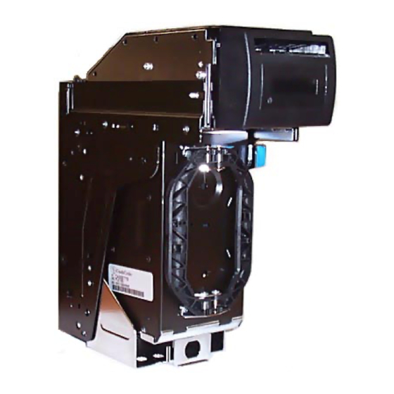
Bill Acceptor FL Series Service Manual PRODUCT OVERVIEW CashCode’s FrontLoad bill validator was developed to validate a wide variety of currencies. The unit’s modular design provides extreme flexibility, allowing you to customize the bill validator to suit your individual requirements. - Page 5 The FrontLoad bill validator consists of six main modules. Each module is available in different variations, to suit your needs. The picture below illustrates the different modules. Memory Card (for software update) Validating Head Bezel (CashCode Standard Bezel is shown) Housing (for 600 Cassette with Lock Bracket is shown) Power Interface Module...
- Page 6 Bill Acceptor FL Series Service Manual The FrontLoad bill validator is designed accommodate bills of different sizes from 62 to 82 mm width, and from 125 to 172 mm length – which encompasses most currencies. Certain currencies have different widths depending on denomination. For accurate validation of such currencies, the Validating Head with a centering mechanism should be used.
-
Page 7: General Specifications
FrontLoad Bill Validator Series - Operation and Service Manual GENERAL SPECIFICATIONS Acceptance: Bills......................lengthwise 4 ways Barcoded Coupons..................two ways, face up Validation rate................96% or higher on first insertion Width of bill, in mm....................from 62 to 82 Maximum length of bill, in mm...................172 Minimum length of bill, in mm....................124 Bill escrow........................one bill Barcoded Coupon specifications:... - Page 8 Bill Acceptor FL Series Service Manual GENERAL SPECIFICATIONS (continue) Environment: a. Operating Temperature................0 ºC to +50 ºC b. Storage Temperature................. -30 ºC to +60 ºC c. Humidity (non-condensing)................30%-90%RH page 1-8 Part 1. Operation Manual Rev. 03-2004...
-
Page 9: Dimensions
FrontLoad Bill Validator Series - Operation and Service Manual DIMENSIONS BILL VALIDATOR WITH STANDARD BEZEL, 600 BILL CASSETTE AND LOCKING MECHA- NISM PAGE 1-9 Rev. 03-2004 Part 1. Operation Manual... - Page 10 Bill Acceptor FL Series Service Manual BILL VALIDATOR WITH STANDARD BEZEL, 600 BILL CASSETTE AND NON-LOCKING MECHANISM page 1-10 Part 1. Operation Manual Rev. 03-2004...
- Page 11 FrontLoad Bill Validator Series - Operation and Service Manual BILL VALIDATOR WITH STANDARD BEZEL, 1000 BILL CASSETTE AND LOCKING MECHA- NISM PAGE 1-11 Rev. 03-2004 Part 1. Operation Manual...
- Page 12 Bill Acceptor FL Series Service Manual BILL VALIDATOR WITH STANDARD BEZEL, 1000 BILL CASSETTE AND NON- LOCKING MECHANISM page 1-12 Part 1. Operation Manual Rev. 03-2004...
- Page 13 FrontLoad Bill Validator Series - Operation and Service Manual BILL VALIDATOR WITHOUT BEZEL, 600 BILL CASSETTE AND LOCKING MECHANISM PAGE 1-13 Rev. 03-2004 Part 1. Operation Manual...
- Page 14 Bill Acceptor FL Series Service Manual BILL VALIDATOR WITH SMART CARD READER, 600 BILL CASSETTE AND LOCKING MECHANISM page 1-14 Part 1. Operation Manual Rev. 03-2004...
-
Page 15: General Wiring Diagram
FrontLoad Bill Validator Series - Operation and Service Manual GENERAL WIRING DIAGRAM PAGE 1-15 Rev. 03-2004 Part 1. Operation Manual... -
Page 16: Modular System
Bill Acceptor FL Series Service Manual MODULAR SYSTEM A Modular System is an interchangeable group of parts – easily configured to a user’s specifications. Below is a more detailed description of each module and its features. VALIDATING HEAD The Validating Head has the following options: The Validating Head with a fixed-width path is available for bill widths 62, 64, 66, 68, 70, 72, 74, 76, 78, 80 and 82 mm. - Page 17 FrontLoad Bill Validator Series - Operation and Service Manual 3) The “Model” of Validating Head reflects the type of electronics used within, and determines the compatibility with other modules. i l i l l i l l i l l i l l i l l i l l i...
- Page 18 Bill Acceptor FL Series Service Manual Listed below are the Validating Heads for different countries. d i l i t n l i z i n i c i l l i h i r f page 1-18 Part 1. Operation Manual Rev.
- Page 19 FrontLoad Bill Validator Series - Operation and Service Manual SENSE-A-CLICK ® MODULES ™ “Sense-a-Click ” sensor paks are a set of two modules – one upper and one lower. In order to be compatible with each other, both modules must have the same part and model number. ™...
- Page 20 Bill Acceptor FL Series Service Manual POWER INTERFACE MODULE The Power Interface Module offers the following options: 1) Input power: 12 VDC or 24 VDC; 2) Interface (see chart below for complete list of interfaces); 3) Model: reflects type of electronics within (A – with linear voltage regulation, B – with switching voltage regulation).
- Page 21 FrontLoad Bill Validator Series - Operation and Service Manual HOUSING Housing offers the following options: 1) Size of supporting bracket: 2 sizes are available – 600 bill Cassettes and 1000 bill Cassettes; 2) Locking mechanism in supporting bracket: Lockable bracket and Plain bracket are available. Locking mechanism can operate with a ¾”...
- Page 22 BEZELS CashCode Bill Validator compatible with different door styles. Normally, the Bill Validator is supplied with the Standard CashCode Bezel. Each type of bezel is available for different bill path widths (path width for the bezel and l l i Validating Head must be the same).
- Page 23 FrontLoad Bill Validator Series - Operation and Service Manual CashCode Bezel with runway lights and Infrared l l i , h t communication port. In addition to runway lights, g i l an IR communication port is provided. IR communication port...
- Page 24 Bill Acceptor FL Series Service Manual CashCode Bezel with Smart Card reader. l l i The Card Reader can support up to 4 different f n I payment systems simultaneously. Runway lights Digital display Slot for Smart Card Infrared communica- tion port CashCode Bezel for “Double Diamond”...
- Page 25 FrontLoad Bill Validator Series - Operation and Service Manual GPT compatible Bezel with runway lights. l l i Metal coin-proof Bezel. l l i Metal coin-proof reversed Bezel. l l i For FL/MFL installed cassette up. PAGE 1-25 Rev. 03-2004 Part 1.
- Page 26 Bill Acceptor FL Series Service Manual Open metal Bezel. l l i Cole compatible Bezel. Variant A l l i Cole compatible Bezel. Variant B l l i page 1-26 Part 1. Operation Manual Rev. 03-2004...
- Page 27 FrontLoad Bill Validator Series - Operation and Service Manual Cole compatible Bezel. Variant C l l i Cole compatible Bezel. Variant D l l i PAGE 1-27 Rev. 03-2004 Part 1. Operation Manual...
- Page 28 Bill Acceptor FL Series Service Manual ACCESSORIES Accessories, typically supplied with the Bill Validator, include an extractor (a special tool for replacing the Sense-a-Click ® sensor pak Lower module, part number OPT-HW-FT01) and a harness (cable) for external connections. OPT-HW-FT01 If no special requirements have been indicated, then the cable will automatically come with 12 “loose”...
- Page 29 600 bill cassette The following types of cassettes are available: l l i , h t a l l , y t s l l 1000 bill cassette For other cassettes, please contact CashCode. PAGE 1-29 Rev. 03-2004 Part 1. Operation Manual...
- Page 30 (and local network). Other interfaces do not support this download feature. Down- loads in this case can be completed with any personal computer (PC or laptop) and a CashCode adapter. (The Validator must be temporarily disconnected from the host controller).
-
Page 31: Choosing Part Numbers For The Bill Validator
In cases where the combination of features selected by the user is not possible, the user will receive a message that the part number does not exist – and a letter to the CashCode Engineering department will be generated. This system was choosen because the total number of all possible part combinations can reach up to 70,000! As a result, part numbers are assigned gradually when an actual request is received. -
Page 32: Installation
Bill Acceptor FL Series Service Manual INSTALLATION The Bill Validator is installed by using (3) M4 screws on each side of the FrontLoad frame. The length of these screws should not be longer than required, otherwise they may protrude through the inside of the frame. - Page 33 FrontLoad Bill Validator Series - Operation and Service Manual LOCK INSTALLATION TO BILL VALIDATOR BASE (600 BILLS) Step #1. Remove the Screw and Lock Washer from the Lock Cover. DO NOT DISCARD! (FIG. 1) Step #2. Remove and discard the Washer and Spacer (FIG. 1) Step #3.
- Page 34 Bill Acceptor FL Series Service Manual LOCK INSTALLATION TO BILL VALIDATOR BASE (600 BILLS) (continued) Screw M3x16, Pan Head, Zinc (8201955) Lock Washer Internal Tooth, Zinc (8203002) FL HOUSING page 1-34 Part 1. Operation Manual Rev. 03-2004...
- Page 35 FrontLoad Bill Validator Series - Operation and Service Manual LOCK INSTALLATION TO BILL VALIDATOR BASE (1000 BILLS) Step #1. Remove the Screw and Lock Washer from the Lock Cover. DO NOT DISCARD! (FIG. 1) Step #2. Remove and discard the Washer and Spacer (FIG. 1) Step #3.
- Page 36 Bill Acceptor FL Series Service Manual LOCK INSTALLATION TO BILL VALIDATOR BASE (1000 BILLS) (continued) Lock Washer M3, Internal Tooth, Zinc (8203002) Screw M3x16, Pan Head, Zinc (8201955) (3 pcs.) FL HOUSING page 1-36 Part 1. Operation Manual Rev. 03-2004...
- Page 37 FrontLoad Bill Validator Series - Operation and Service Manual LOCK INSTALLATION TO CASSETTE In order to install the security locks into the Cassette, open the Cassette cover, remove the plastic lock and plug, and follow the diagram shown below: 12.7max "±...
-
Page 38: Interface Connection
Type 4: RS232 levels, 24 Volt DC, CCNET (single slave mode) or CC-GPC22. For detailed interface descriptions, please refer to the corresponding Interface Description Manual. The manual may be downloaded from the CashCode website at www.cashcode.com . The type of interface hardware depends on the base assembly interface module. - Page 39 FrontLoad Bill Validator Series - Operation and Service Manual Signal Descriptions for the RS232 12Volt version (Type2, Type3) Signals Description for RS232 24 Volt version (Type4): PAGE 1-39 Rev. 03-2004 Part 1. Operation Manual...
- Page 40 Bill Acceptor FL Series Service Manual INPUT/OUTPUT CIRCUITS OPTO-ISOLATED VERSION PC400 PC357NT DD1B DD1D MC74HC132AD PC400 MC74HC132AD 5.1K DD1A MC74HC132AD +12V +12V Power - Power + No.747843-4 CONNECTOR DB37 12 JAE HEADER page 1-40 Part 1. Operation Manual Rev. 03-2004...
-
Page 41: Switch Settings
Validation Mode: This is the mode for normal operation. If a red status light is illuminated, it indicates that the validator is not ready to accept currency. Service Mode: This is the mode for programming and testing the CashCode Bill Validator. PAGE 1-41 Rev. - Page 42 Bill Acceptor FL Series Service Manual A series of (8) position DIP switches (SW1) define the settings and program the Bill Validator to recognize and validate a variety of different bill denominations. ON State of switch OFF State of switch DIP SWITCH SW1 SETTINGS: For a complete explanation of switch descriptions, please see the software version description.
- Page 43 FrontLoad Bill Validator Series - Operation and Service Manual The (4) position DIP switches (SW2) are defined below: ON State of switch OFF State of switch l l i For additional information on switch features and explanations, please see the software description for your particular Bill Validator.
-
Page 44: Maintenance & Service
MAINTENANCE & SERVICE Collecting Bills To collect bills from the CashCode Bill Validator, simply open the lock on the base assembly and pull out the Cassette (please see diagram below). Pressing the lever (located to the right) releases the Cassette for easy removal. - Page 45 FrontLoad Bill Validator Series - Operation and Service Manual To open the Cassette cover, simply open the locks – located on the Cassette cover (as shown in diagram below). The Cassette cover will then open easily, and the validated pack of bills can then be removed as a neat stack.
-
Page 46: Software Updates
Bill Acceptor FL Series Service Manual SOFTWARE UPDATES The FrontLoad Bill Validator is shipped with pre-installed software, according to a user’s ordered specifications. To ensure the proper operation of the FrontLoad Bill Validator, software updates can be ordered according to the original FrontLoad part number. Download procedure for a single-download Memory Card: Step 1. - Page 47 3. Remove the Dummy Card (or Memory Card) from the Memory Card slot of the Validating Head (please see diagram below). Step 4. Insert the new CashCode Memory Card into the Memory Card slot of the Validating Head (please see diagram below). PAGE 1-47 Rev.
- Page 48 Bill Acceptor FL Series Service Manual Step 5. Insert the Validating Head into the Housing. Step 6. Turn Power ON and wait until the download process is completed. During the download, a red-green status light will blink. Once the download is completed, the diagnostic light will turn green. Should the light stay red, this means there is no communication between the FrontLoad Bill Validator and the host controller.
- Page 49 4. Install the Validating Head into the Housing. Step 5. Connect the CashCode Adaptor (see page 23 for exact type): a) to the Computer, b) to the interface connector of the Bill Validator, and c) to the power outlet (AC 100-250V).
-
Page 50: Troubleshooting
Bill Acceptor FL Series Service Manual TROUBLESHOOTING CashCode’s FrontLoad Bill Validator is equipped with a self-diagnostic feature to aid in repair and maintenance. When the power to the Bill Validator is turned ON, the Bill Validator begins its self- diagnostic operation. - Page 51 FrontLoad Bill Validator Series - Operation and Service Manual OPERATION MODE DIAGNOSTICS Cassette PAGE 1-51 Rev. 03-2004 Part 1. Operation Manual...
- Page 52 Bill Acceptor FL Series Service Manual EXTRACTOR OPT-HW-FT01 SENSE-A-CLICK (Lower Module) SENSE-A-CLICK (Upper Module) GUIDE (0200052) GUIDE (0200053) page 1-52 Part 1. Operation Manual Rev. 03-2004...
- Page 53 FrontLoad Bill Validator Series - Operation and Service Manual PAGE 1-53 Rev. 03-2004 Part 1. Operation Manual...
- Page 54 Bill Acceptor FL Series Service Manual page 1-54 Part 1. Operation Manual Rev. 03-2004...
- Page 55 FrontLoad Bill Validator Series - Operation and Service Manual “SENSE-A-CLICK” OPTICAL SENSORS OPTICAL SENSORS INDUCTIVE SENSORS PAGE 1-55 Rev. 03-2004 Part 1. Operation Manual...
- Page 56 Bill Acceptor FL Series Service Manual " . " Validating Head Transport motor page 1-56 Part 1. Operation Manual Rev. 03-2004...
- Page 57 FrontLoad Bill Validator Series - Operation and Service Manual " . " PAGE 1-57 Rev. 03-2004 Part 1. Operation Manual...
-
Page 58: Technical Support
Bill Acceptor FL Series Service Manual TECHNICAL SUPPORT CashCode Corporate Headquarters: CashCode Company Inc. 553 Basaltic Road Concord, Ontario Canada L4K 4W8 Phone: 1-800-584-2633 (1-905-303-8874) Fax: 1-800-593- 2633 (1-905-303-8875) E-mail: support@cashcode.com Website: www.cashcode.com page 1-58 Part 1. Operation Manual Rev. 03-2004...
Need help?
Do you have a question about the FrontLoad Series and is the answer not in the manual?
Questions and answers