Table of Contents
Advertisement
Advertisement
Chapters
Table of Contents

Related Manuals for Sailor RM2042


Summary of Contents for Sailor RM2042
- Page 1 S.P. RADIO A/S AALBORG DENMARK...
- Page 3 RM2042 INSTALLATION INFORMATION RM2042 This VHF DSC RM2042 is delievered with the service switch in position Service Mode. After programming of MMSI number the service switch must turned into position User Mode. Please refer to the drawing below. User mode...
-
Page 5: Table Of Contents
RM2042 CONTENTS INTRODUCTION GENERAL DESCRIPTION TECHNICAL DATA CONTROLS PRINCIPLE OF OPERATION AND BLOCK DIAGRAM INSTALLATION MOUNTING POSSIBILITIES POWER SUPPLY HANDSET ANTENNA ELECTRICAL CONNECTIONS SERVICE MAINTENANCE ALIGNMENT INSTRUCTIONS PROPOSAL FOR NECESSARY TEST EQUIPMENT TROUBLE SHOOTING PERFORMANCE CHECK ADJUSTMENT PROCEDURE REPLACEMENT OF COMPONENTS... -
Page 7: Introduction
RM2042 CONTENTS INTRODUCTION GENERAL DESCRIPTION TECHNICAL DATA CONTROLS PRINCIPLE OF OPERATION AND BLOCK DIAGRAM 9716... - Page 9 Furthermore the units can be combined with other compact 2000 units to form a complete GMDSS installation. The RM2042 combines the IMO requirements on safety, with a lot of user convenient features to be used in normal VHF-communication. And of course a high security scrambler can be combined with the system.
- Page 10 1 INTRODUCTION RM2042 1.1 GENERAL DESCRIPTION RM2042 is a complete VHF receiver-modem, for digital selective calling on the VHF-channels. RM2042 maintains a continous watch of the calling channel 70, by means of the build-in receiver. RM2042 decodes and encodes all the messages applicable for a VHF Class A DSC-equipment, as prescribed by international authorities.
- Page 11 1 INTRODUCTION RM2042 1.2 TECHNICAL DATA Complies with IMO, ITU, CEPT and other national requirements. GENERAL Operation: As CCIR Rec. 541-3 Protocol: As CCIR Rec. 493-4 as VHF Class A equipment. Printer Interface: Parallel Centronics. Navigator Interface: NMEA 0183 Power Supply:...
-
Page 12: Controls
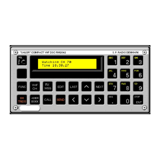
1 INTRODUCTION RM2042 1.3 CONTROLS SAILOR COMPACT VHF DSC RM2042 S.P. RADIO DENMARK FUNC EDIT LAST NEXT STOP ADDR CALL SEND TRESS BOOK 27552 On/off/vol turn-style knob. Selects the function menu window, from which one of seven different functions can be selected, such as the display control functions, printer function etc. - Page 13 1 INTRODUCTION RM2042 This button is used to step backward, to the last selected menu window in an input sequence. LAST These buttons is used to scroll between the possible choices in the actual diplayed menu. Note that these buttons only will be active, when their signs are shown in the display readout.
-
Page 14: Principle Of Operation And Block Diagram
1 INTRODUCTION RM2042 1.4 PRINCIPLE OF OPERATION AND BLOCK DIAGRAM RECEIVER The RF-signal from the antenna is feed to the input amplifier circuit. Here is the initial filtering made by means of a fixed, double tuned filter before the signal is amplified in the front-end amplifier. This amplifier is followed by another fixed, double tuned filter. - Page 15 1 INTRODUCTION RM2042 MICROPROCESSOR The microprocessor module contains as the central unit, the microprocessor IC, a fast 16 bit type, with its external program memory and RAM circuits. The microprocessor clock-signal is derived from an 8 MHz XTAL-oscillator. The non-volatile memory consist of a single 8kByte EEPROM, where the received messages and internal programable settings are stored.
- Page 17 1 INTRODUCTION RM2042 BLOCK DIAGRAM RM2042 14.850MHz RECEIVER MICROPROCESSOR DISPLAY UNIT (MODULE 3) (MODULE 2) (MODULE 4) 15.3MHz Limit amp. First 2’d Mixer AF-filter IF-filter & AF-detect amp. mixer & osc. -6 dB/oct. amp. RF-level det. 8.000MHz PROM EPROM XTAL...
-
Page 19: Installation
RM2042 CONTENTS INSTALLATION MOUNTING POSSIBILITIES POWER SUPPLY HANDSET ANTENNA ELECTRICAL CONNECTIONS 9716... - Page 21 2.1 MOUNTING POSSIBILITIES The VHF DSC RM2042 cabinet is designed in a module called a mini 1/4 box. For this module we can supply a wide variety of installation brackets etc. which will be described below. We have made a drawing including dimensions and drilling plan for each type and we kindly ask you to look at the drawing for the type in question.
- Page 22 H2067 MOUNTING BRACKET FOR TABLETOP, BULKHEAD OR DECKHEAD MOUNTING FOR MINI 1/4 BOX This mounting bracket is used when RM2042 is to be mounted next to other units in the Compact 2000 programme mounted in H2055 mounting brackets. For example when installing the RM2042 next to the HF SSB RE2100 it is possible to tilt both units in the same angle.
- Page 23 VHF plug ** dimensions when using a standard VHF plug 4 pcs 5 mm min 169mm* max 185mm** 238mm 27597 27574A 4 pcs 5 mm 206mm Weight: Mounting kit H2057: 0.4 kg VHF DSC RM2042: 2.0 kg 27575A PAGE 2-3...
- Page 24 240mm 4.5mm 4.5mm 4 stk 6mm 4 stk 3.5mm uns for M3 DIN 963 Cutting out 231x100mm Mounting kit H2063: 1.0 kg VHF DSC RM2042: 2.0 kg 27444A Weight: 4 pcs M3x30 8 pcs M5x8 4 pcs M5x30 27581 PAGE 2-4...
-
Page 25: Handset
Strap for connection to external supply (12V) The cable for the handset is five-cored and must be connected to the rear of RM2042 by means of the 9 pole SUB-D connector J1-1. For installation of the cable, please see the drawings of the mounting brackets. The cable grommet must be placed in the most convenient groove in the mounting bracket. -
Page 27: 2.5 Electrical Connections
2 INSTALLATION RM2042 2.5 ELECTRICAL CONNECTIONS Connector for Power Supply Antenna terminal 501224 Connector for VHF Connector for Connector for Connector for NMEA Interface Radiotelephone Handset Printer PC/Remote Distress Unit (C2149) POWER CONNECTOR PIN 1 EXT. LOUDSPEAKER PIN 2 REMOTE AL. CIRC. - Page 28 2 INSTALLATION RM2042 CONNECTOR FOR VHF PIN 1 TELEPHONE PIN 2 PIN 3 MIC.GND PIN 4 MIC./TX AF + PIN 5 RX AF FROM VHF PIN 6 PIN 7 DISTRESS / BUS INTERRUPT PIN 8 DATA/TX AF - PIN 9...
-
Page 29: Service
RM2042 CONTENTS SERVICE MAINTENANCE ALIGNMENT INSTRUCTIONS PROPOSAL FOR NECESSARY TEST EQUIPMENT TROUBLE SHOOTING PERFORMANCE CHECK ADJUSTMENT PROCEDURE 3.6.1 ADJUSTMENT OF INTERFACE (MODULE 1) 3.6.2 ADJUSTMENT OF MICROPROCESSOR (MODULE 2) 3.6.3 ADJUSTMENT OF RECEIVER (MODULE 3) REPLACEMENT OF COMPONENTS REPLACEMENT OF MODULES... - Page 31 The RM2042 is constructed with a real time clock, which uses a lithium battery for power back-up. By means of this battery, it is possible to maintain track of time and date even though the RM2042 has been turned off.
- Page 32 3 SERVICE RM2042 3.3 PROPOSAL FOR NECESSARY TEST EQUIPMENT OSCILLOSCOPE: Bandwidth DC-35 MHz Sensitivity 2mV/div Input Impedance 1 Mohm//20 pF E.g. Philips type PM3050 PASSIVE PROBE: Attenuation 20 dB Input Impedance 10 Mohm//15 pF Compensation Range 10-30 pF E.g. Philips type...
- Page 33 Press ‘NEXT’ and ‘SEND’ for transmission of the DSC call. The DSC call should now be received by the RM2042 and the alarm signal will be heard in the internal loudspeaker. The RM2042 will write the received message to the printer.
- Page 34 DSC unit it self. NOTE! To perform this test, it is necessary to change the operation mode of the RM2042 from user to service mode. This change of operation mode is only allowed for trained technicians and the information of how to do it, is therefore only included in the DSC-VHF INSTALLATION GUIDE.
- Page 35 The TX AF level is controlled by checking that the peak diviation of the transmitted RF-signal is correct. NOTE! To perform this test, it is necessary to change the operation mode of both the RM2042 and the VHF tranceiver from user to service mode. This change of operation mode is only allowed for trained technicians and the information of how to do it is therefore only included in the DSC-VHF INSTALLATION GUIDE.
-
Page 36: 3.6 Adjustment Procedure
SUB-D connector P2-1 at the interface module. NOTE! To perform this test, it is necessary to change the operation mode of the RM2042 from user to service mode. This change of operation mode is only allowed for trained technicians and the information of how to do it is therefore only included in the DSC-VHF INSTALLATION GUIDE. -
Page 37: Adjustment Of Microprocessor (Module 2)
ADJUSTMENT OF BALANCED TX AF AMPLIFIER When the RM2042 is used as an encoder in a semi automatic system, the balanced TX AF output has to be used. The balanced amplifier is build-up around the operational amplifier U3.2-1, the transistor Q4- 1 and the transformer TR1-1. -
Page 38: Adjustment Of Receiver (Module 3)
3 SERVICE RM2042 3.6.3 ADJUSTMENT OF RECEIVER (MODULE 3) ADJUSTMENT OF FIRST LOCAL OSCILLATOR The 1st. local oscillator is adjusted by the coil L6-3. Connect a frequency counter by means of a passive probe to the tap of the two capacitors C89- 3 and C90-3. - Page 39 R93-3. Connect the RM2042 to the VHF tranceiver by means of the 9 pole SUB-D connector. Apply an unmodulated carrier with the frequncy 156.525 MHz to the antenna terminal at the connected VHF tranceiver and adjust the output level of the RF-signal generator to -126 dBm (EMF: -13 dB/µV).
-
Page 40: Repair/Replacement Of Interface Module (Module 1)
REPAIR/REPLACEMENT OF INTERFACE MODULE (MODULE 1) REPLACEMENT OF INTERFACE MODULE (MODULE 1) If the RM2042 is used in a semi automatic system, where the balanced TX AF amplifier is used, it is necessary to perform section 3.6.1, “ADJUSTMENT OF BALANCED TX AF AMPLIFIER” and then perform section 3.5, “CHECK OF SYSTEM PERFORMANCE”... -
Page 41: Repair/Replacement Of Receiver Module (Module 3)
3 SERVICE RM2042 REPAIR IN 32.768 kHz OSCILLATOR (MODULE 2) Perform section 3.6.2, “ADJUSTMENT OF 32.768 kHz OSCILLATOR”. Check that the real time clock is performing correctly, by inspection of the display. 3.9.3 REPAIR/REPLACEMENT OF RECEIVER MODULE (MODULE 3) REPLACEMENT OF RECEIVER MODULE (MODULE 3) If the receiver module is replaced with a new one, which is factory adjusted, it is only necessary to perform section 3.5, “CHECK OF SYSTEM PERFORMANCE”. - Page 42 3 SERVICE RM2042 3.10 PIN CONFIGURATIONS DIODE: BAT54S (SOT-23 CASE) TRANSISTOR: BC848B, BC858B, BFR92A (SOT-23 CASE) BF996SB (SOT-143 CASE) BCP52-16, BCP55-16 (SOT-223 CASE) TIS88 (SOT-23 CASE) Source Gate Drain Top view VOLTAGE REGULATOR and CONVERTER: 7805 (TO-220 CASE) 78M05 (DPAK PACKAGE)
- Page 43 3 SERVICE RM2042 INTEGREATED CIRCUIT, ANALOG: LM324 (SO-8 PACKAGE) LM339 (SO-8 PACKAGE) MC3372 (SO-16 CASE) Filter Squelch Trigger with Hysteresis Demodulator Limiter Mixer 10pF Oscillator TDA7052 (DIL-8 PACKAGE) OUTPUT 2 OUTPUT 1 INPUT INPUT GROUND GROUND GROUND OUTPUT 2 OUTPUT 1...
- Page 44 3 SERVICE RM2042 INTEGREATED CIRCUIT, DIGITAL: 68HC000 (68-LEAD PLCC PACKAGE) *DTACK *BGACK TOP VIEW *HALT *RESET *VMA *VPA *BERR *IPL2 *IPL1 MSM5165/OKI & HM6264/HITACHI (28-LEAD FLAT-PACK) 27PC512 (28-LEAD PLCC PACKAGE) (PWR DWN) & *G/VPP PAGE 3-14 9403...
- Page 45 3 SERVICE RM2042 28C64A (32-LEAD PLCC PACKAGE) 71051/NEC & 82C51/OTHERS (28-LEAD PLCC PACKAGE) 71054/NEC & 82C54/OTHERS (28-LEAD PLCC PACKAGE) 9403 PAGE 3-15...
- Page 46 3 SERVICE RM2042 71055/NEC & 82C55/OTHERS (44-LEAD PLCC PACKAGE) 8573A (28-LEAD PLCC PACKAGE) AD232 (SO-16L PACKAGE) PAGE 3-16 9403...
- Page 47 3 SERVICE RM2042 MOC207 (SO-8 PACKAGE) 74HC00 (SO-14 PACKAGE) 74HC02 (SO-14 PACKAGE) 74HC04 (SO-14 PACKAGE) 74HC05 (SO-14 PACKAGE) 74HC08 (SO-14 PACKAGE) 74HC14 (SO-14 PACKAGE) 74HC21 (SO-14 PACKAGE) 74HC32 (SO-14 PACKAGE) 74HC74 (SO-14 PACKAGE) 9403 PAGE 3-17...
- Page 48 3 SERVICE RM2042 74HC32 (SO-14 PACKAGE) 74HC74 (SO-14 PACKAGE) 74HC132 (SO-14 PACKAGE) 74HC138 (SO-16 PACKAGE) 74HC148 (SO-16 PACKAGE) PAGE 3-18 9403...
- Page 49 3 SERVICE RM2042 74HC154 (SO-24L PACKAGE) 74HC174 (SO-16 PACKAGE) 74HC393 (SO-14 PACKAGE) 74HC4053 (SO-16PACKAGE) 74HC4040 (SO-16 PACKAGE) 9403 PAGE 3-19...
-
Page 51: Mechanical Description
RM2042 CONTENTS MECHANICAL DESCRIPTION MECHANICAL DISASSEMBLING AND UNITS LOCATION 9716... - Page 53 RM2042 MECHANICAL DESCRIPTION 4.1 MECHANICAL DISASSEMBLING AND UNITS LOCATION Top view Buttom view Screw for front plate Screw for cover Front view without frontplate Screw for Microprocessor module Screw for Display section Clock backup battery DSC AF-output selection switch Unbalanced AF-output...
-
Page 55: Circuit Description And Schematic Diagrams
RM2042 CONTENTS CIRCUIT DESCRIPTION AND SCHEMATIC DIAGRAMS INTERFACE (MODULE 1) PART NO. 626941 MICROPROCESSOR (MODULE 2) PART NO. 626942 RECEIVER (MODULE 3) PART NO. 626943 5-13 DISPLAY UNIT (MODULE 4) PART NO. 626944 5-23 KEYBOARD UNIT (MODULE 6) PART NO. 625636... -
Page 57: Interface (Module 1) Part No. 626941
600 ohm generator impedance. To establish a balanced connection between RM2042 and the connected VHF radiotelephone, it will be necessary to use two wires, while an unbalanced connection only requires one. Because the number of wires in the connection cable is limit to nine and all are in use, it is necessary to change the function of the serial data bus and use this as the second wire in the balanced connection. - Page 58 If the power supply is completely lost, the RM2042 will simply be turned off and when the power supply is re-established, the RM2042 will be restarted by a power on reset pulse, generated at the microproc- essor module.
- Page 59 U2.1, using half duplex communication. In order to avoid conflict on the line, a master/slave relationship is established. RM2042 is the master and has control over the line. If the VHF wants to use the line it interrupts RM2042 via pin 7 in P2.
- Page 60 5 CIRCUIT DESCRIPTION AND SCHEMATIC DIAGRAMS RM2042 COMPONENT LOCATION INTERFACE MODULE 1 Seen from component side with upper side tracks. Seen from soldering side with lower side tracks. PCB rev. 26941F PAGE 5-4 9341...
- Page 61 5 CIRCUIT DESCRIPTION AND SCHEMATIC DIAGRAMS RM2042 INTERFACE MODULE 1 This diagram is valid for PCB rev. 26941F 9341 PAGE 5-5...
- Page 62 5 CIRCUIT DESCRIPTION AND SCHEMATIC DIAGRAMS RM2042 PAGE 5-6 9341...
-
Page 63: Microprocessor (Module 2) Part No. 626942
5 CIRCUIT DESCRIPTION AND SCHEMATIC DIAGRAMS RM2042 5.2 MICROPROCESSOR (MODULE 2) PART NO. 626942 The microprocessor module contains a micro computer, build round a general purpose microprocessor with its basic external control logic, memory banks and timers. Furthermore the microprocessor module contains a syncronus receiver, and three 8 bit ports. - Page 64 For reference, the 32.768 kHz is output on pin 16 (MFO). The oscillation frequency can be adjusted to the nominal value by use of C39. When RM2042 is turned on, and a message appears, telling that the time has stopped running, the battery may be extinct, and has to be replaced.
- Page 65 5 CIRCUIT DESCRIPTION AND SCHEMATIC DIAGRAMS RM2042 Output pin PB4 is used to control a remote alarm circuit. Output pin PB5 is used to control the relay on the interface module. Output pin PB6 is used to control output from the syncronus transmitter U26, and the modem IC on the receiver module.
- Page 66 5 CIRCUIT DESCRIPTION AND SCHEMATIC DIAGRAMS RM2042 COMPONENT LOCATION MICROPROCESSOR MODULE 2 Seen from component side with upper side tracks. Seen from component side with lower side tracks. PCB rev. 26942L PAGE 5-10 9716...
- Page 67 5 CIRCUIT DESCRIPTION AND SCHEMATIC DIAGRAMS RM2042 MICROPROCESSOR MODULE 2 PAGE 5-11 This diagram is valid for PCB rev. 26942L 9505...
- Page 68 5 CIRCUIT DESCRIPTION AND SCHEMATIC DIAGRAMS RM2042 PAGE 5-12 9341...
-
Page 69: Receiver (Module 3) Part No. 626943
The input signal to the receiver, which is an FM signal, is received by means of a separate antenna connected directly to the RM2042. First Mixer... - Page 70 5 CIRCUIT DESCRIPTION AND SCHEMATIC DIAGRAMS RM2042 The crystal X3 is constructed to work at the 7th. overtone and is used in a series resonance mode. Unfortunately the crystal has also a parallel resonance frequency, which is located only 4 to 5 kHz above the wanted series resonance.
- Page 71 5 CIRCUIT DESCRIPTION AND SCHEMATIC DIAGRAMS RM2042 An exact copy of this de-emphasis filter, with the same component values, is used in the receiver signal path from the connected VHF radiotelephone. This filter is build-up around the operational amplifier U7.3.
- Page 72 The function of the signal switches and the corresponding control logic is described by the block diagram below, which also include the logical circuits used to genereate the CH70 CARRIER DETECT, VHF CARRIER DETECT and MODULATION DETECT signals. RM2042 Receiver (Module 3) U7.3 External...
- Page 73 5 CIRCUIT DESCRIPTION AND SCHEMATIC DIAGRAMS RM2042 CHANNEL-70 CARRIER DETECT The receiver module is constructed with two identicale carrier detect circuits - one for the build-in channel- 70 receiver and one for the external connected VHF radiotelephone. The carrier detect circuit for the build-in channel-70 receiver is included to avoid emission of a DSC call, while an other unit is transmitting.
- Page 74 5 CIRCUIT DESCRIPTION AND SCHEMATIC DIAGRAMS RM2042 CH70 CARRIER VHF CARRIER AF SIGNAL MODULATION REMARKS DETECT DETECT DETECT DETECT No carrier detected at CH70 receiver, and no carrier detected at ext. VHF. Af signal detected because of noise. Non existing combination.
- Page 75 5 CIRCUIT DESCRIPTION AND SCHEMATIC DIAGRAMS RM2042 9341 PAGE 5-19...
- Page 76 5 CIRCUIT DESCRIPTION AND SCHEMATIC DIAGRAMS RM2042 COMPONENT LOCATION RECEIVER MODULE 3 Seen from component side with upper side tracks. Seen from component side with lower side tracks. PCB rev. 26943E PAGE 5-20 9716...
- Page 77 5 CIRCUIT DESCRIPTION AND SCHEMATIC DIAGRAMS RM2042 RECEIVER MODULE 3 This diagram is valid for PCB rev. 26943E 9716 PAGE 5-21...
- Page 78 5 CIRCUIT DESCRIPTION AND SCHEMATIC DIAGRAMS RM2042 PAGE 5-22 9341...
-
Page 79: 5.4 Display Unit (Module 4) Part No. 626944
5 CIRCUIT DESCRIPTION AND SCHEMATIC DIAGRAMS RM2042 5.4 DISPLAY UNIT (MODULE 4) PART NO. 626944 An LCD display of 2 times 24 characters with LED backlight is used to read out information to the operator. DISPLAY MODULE The display module is mounted on top of the display unit by means of two connectors and four screws. - Page 80 5 CIRCUIT DESCRIPTION AND SCHEMATIC DIAGRAMS RM2042 COMPONENT LOCATION DISPLAY UNIT MODULE 4 Seen from component side with upper side tracks. Seen from component side with lower side tracks. PCB rev. 26944F 9739 PAGE 5-24...
- Page 81 5 CIRCUIT DESCRIPTION AND SCHEMATIC DIAGRAMS RM2042 DISPLAY UNIT MODULE 4 This diagram is valid for PCB rev. 26944F 9915 PAGE 5-25...
- Page 82 5 CIRCUIT DESCRIPTION AND SCHEMATIC DIAGRAMS RM2042 PAGE 5-26 9341...
-
Page 83: 5.6 Keyboard Unit (Module 6) Part No. 625636
5 CIRCUIT DESCRIPTION AND SCHEMATIC DIAGRAMS RM2042 5.6 KEYBOARD UNIT (MODULE 6) PART NO. 625636 The keyboard consist of a 4 times 8 matrix of which 26 keys are used. The 4 rows are set high alternately and by reading the output at the 8 columns it is possible to determine which key has been activated. -
Page 85: Microtelephone Installation
RM2042 CONTENTS MICROTELEPHONE INSTALLATION SPECIAL INSTALLATION WITH 2 MICROTELEPHONES SPECIAL INSTALLATION WITH 3 MICROTELEPHONES: MECHANICAL DIMENSIONS FOR HANDSET 9716... - Page 87 RM2042 MICROTELEPHONE INSTALLATION VHF RT2047 SCRAMBLER CRY2001, RE2100, RT2047 prepared for DSC and RT2048 SHORTWAVE S130X YELLOW YELLOW WHITE BROWN BROWN BROWN TC801 TC1701 HAND KEY HAND KEY HAND KEY S801 S1701 P1701 P803 MIC PRE-AMP MIC PRE-AMP MIC PRE-AMP...
- Page 88 6 MICROTELEPHONE INSTALLATION RM2042 MICROTELEPHONE WITH ELECTRET MIC. AMP. ECI A/S 4-6-24025D/4-0-24025E 600875 POSITION DESCRIPTION MANUFACTOR TYPE PART NR. CAPACITOR ELECTROLYTIC 100uF 20% 10VDC EKI 00 BB 310 C M0E 14.607 CAPACITOR CERAMIC 10nF -20/+80% CL2 50VDC RT-HE70 SK YF 103 Z 15.170...
- Page 89 6 MICROTELEPHONE INSTALLATION RM2042 RM2042 SPECIAL INSTALLATION WITH 2 MICROTELEPHONES: H2086 FOR SCRAMBLER CRY2001, RE2100, RT2048 AND RT2047 PREPARED FOR DSC. H2087 FOR VHF RT2047 AND SSB T2031. MICROTELEPHONE ONE WITH PREFERENCE NORMAL MICROTELEPHONE H2087 H2086 Hook 1 program 2000 (HANDSET)
- Page 90 6 MICROTELEPHONE INSTALLATION RM2042 SPECIAL INSTALLATION WITH 3 MICROTELEPHONES: H2088 FOR SCRAMBLER CRY2001, RE2100, RT2048 AND RT2047 PREPARED FOR DSC. H2089 FOR VHF RT2047 AND SSB T2031. MICROTELEPHONE ONE WITH PREFERENCE NORMAL MICROTELEPHONE H2089 H2088 Hook 1 program 2000 (HANDSET)
- Page 91 6 MICROTELEPHONE INSTALLATION RM2042 RM2042 6.3 MECHANICAL DIMENSIONS FOR HANDSET ø4.5 ø4.5 27946 MECHANICAL DIMENSIONS FOR HANDSET HOLDER WITH MICROSWITCH ø4.5 ø4.5 26999 9440 PAGE 6-5...
- Page 92 6 MICROTELEPHONE INSTALLATION RM2042 MECHANICAL DIMENSIONS FOR HANDSET ø4.5 ø4.5 4-0-29938 MECHANICAL DIMENSIONS FOR HANDSET HOLDER WITH MICROSWITCH ø4.5 ø4.5 4-0-29937 PAGE 6-6 9440...
-
Page 93: Parts List
RM2042 CONTENTS PARTS LIST 9716... - Page 95 RM2042 PARTS LIST VHF DSC RM2042 SAILOR GREEN S.P. RADIO A/S VHF DSC RM2042 802042 POSITION DESCRIPTION MANUFACTOR TYPE PART NO. VARIOUS MINI 1/4 BOX CABINET SAILOR GREEN 225435 GR•N RILSAN 22543500 VARIOUS POWER CABLE WITH PLUG ECI A/S 503758 POWERKABEL...
- Page 96 7 PARTSLIST RM2042 POSITION DESCRIPTION MANUFACTOR TYPE PART NO. C41-1 CAPACITOR CERAM. SMD 0805 2n2F 10% X7R 50VDC MURATA GRM40 X7R 222 K 50 PT 328.328 C42-1 CAPACITOR CERAM. SMD 0805 2n2F 10% X7R 50VDC MURATA GRM40 X7R 222 K 50 PT 328.328...
- Page 97 7 PARTSLIST RM2042 POSITION DESCRIPTION MANUFACTOR TYPE PART NO. R16-1 RESISTOR SMD 0805 2k2 OHM 5% 0.1W ROHM MCR 10 EZH J 222 302.052 R17-1 PRESET SEALED 100k OHM 20% 1/4W BOURNS 3314J-1-104-E(G) 310.412 R18-1 RESISTOR SMD 0805 47k OHM 5% 0.1W...
- Page 98 7 PARTSLIST RM2042 POSITION DESCRIPTION MANUFACTOR TYPE PART NO. INTERFACE MODULE 1 RM2042 ECI A/S 5-0-26941F / 4-0-26941K 62694101 POSITION DESCRIPTION MANUFACTOR TYPE PART NO. C66-1 CAPACITOR CERAM. SMD 0805 100nF 10% X7R 25VDC MURATA GRM40 X7R 104 K 25 PT 328.348...
- Page 99 7 PARTSLIST RM2042 POSITION DESCRIPTION MANUFACTOR TYPE PART NO. C37-2 CAPACITOR CERAM. SMD 0805 100nF 10% X7R 25VDC MURATA GRM40 X7R 104 K 25 PT 328.348 C38-2 CAPACITOR CERAM. SMD 0805 47pF 5% NPO 50VDC C2012 COG 1H 470 J T NiBa 323.082...
- Page 100 28C64A, 28C64B CATALYST CAT28C64BN-20 TE7/TE13 356.210 U2-2 SRAM 8kx8 Taa<=150nSecs UM6264BM,MSM5165AL,HM6264 UMC UM 6264BM-10L 356.310 U3-2 PROGRAMMED PROM U3-2 RM2042 (C1123,“ODD“) ECI A/S 0-0-29653 / C1123D-6A3A 729653 U4-2 SRAM 8kx8 Taa<=150nSecs UM6264BM,MSM5165AL,HM6264 UMC UM 6264BM-10L 356.310 U5-2 PROGRAMMED PROM U5-2 RM2042 (C1124,“EVEN“)
- Page 101 7 PARTSLIST RM2042 POSITION DESCRIPTION MANUFACTOR TYPE PART NO. C6-3 CAPACITOR CERAM. SMD 1206 3p3F +/- 0.25p NPO 500VDC MURATA GRM42-6 COG 3R3 C 500 PT 324.268 C7-3 CAPACITOR CERAM. SMD 0805 6p8F +/-0.25pF N150 50VDC MURATA GRM40 P2H 6R8 C 50 PT 323.472...
- Page 102 7 PARTSLIST RM2042 POSITION DESCRIPTION MANUFACTOR TYPE PART NO. C83-3 CAPACITOR CERAM. SMD 0805 1n0F 10% X7R 50VDC MURATA GRM40 X7R 102 K 50 PT 328.324 C84-3 CAPACITOR CERAM. SMD 0805 1n0F 10% X7R 50VDC MURATA GRM40 X7R 102 K 50 PT 328.324...
- Page 103 7 PARTSLIST RM2042 POSITION DESCRIPTION MANUFACTOR TYPE PART NO. R3-3 RESISTOR SMD 0805 27k OHM 5% 0.1W ROHM MCR 10 EZH J 273 302.065 R4-3 RESISTOR SMD 0805 12k OHM 5% 0.1W ROHM MCR 10 EZH J 123 302.061 R5-3 RESISTOR SMD 0805 22k OHM 5% 0.1W...
- Page 104 7 PARTSLIST RM2042 POSITION DESCRIPTION MANUFACTOR TYPE PART NO. R79-3 RESISTOR SMD 0805 1k0 OHM 5% 0.1W ROHM MCR 10 EZH J 102 302.048 R80-3 RESISTOR SMD 0805 100 OHM 5% 0.1W ROHM MCR 10 EZH J 101 302.036 R81-3 RESISTOR SMD 0805 2k7 OHM 5% 0.1W...
- Page 105 7 PARTSLIST RM2042 POSITION DESCRIPTION MANUFACTOR TYPE PART NO. DISPLAY PRINT RM2042 / RM2150 / RM2151 ECI A/S 5-0-26944F / 4-0-26944G 626944 POSITION DESCRIPTION MANUFACTOR TYPE PART NO. CAPACITOR CERAM. SMD 0805 10nF 10% X7R 50VDC MURATA GRM40 X7R 103 K 50 PT 328.336...
- Page 106 7 PARTSLIST RM2042 POSITION DESCRIPTION MANUFACTOR TYPE PART NO. J1-6 SOCKET 2x7 POLES PCB VERSION 1-215079-4 78.196 R1-6 RESISTOR MF 330 OHM 5% 0.33W PHILIPS 2322 187 73331 02.460 R2-6 RESISTOR MF 680 OHM 5% 0.33W PHILIPS 2322 187 73681 02.468...
Need help?
Do you have a question about the RM2042 and is the answer not in the manual?
Questions and answers