Advertisement
Quick Links
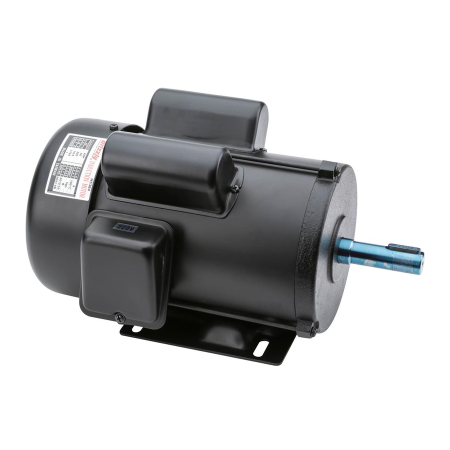
Model H5384 Specifications
Power .......................................................... 2 HP
Cycle ............................................................60Hz
Voltage ........................................................220V
Amps ..........................................................10.5A
RPM ............................................................. 1725
Phase ........................................................ Single
Class ..................................................................B
Start Capacitor ........................ 400MFD 125VAC
Dimensions .............................. 1
Run Capacitor ........................... 70MFD 250VAC
Dimensions .............................. 1
Replaceable Parts
REF PART #
DESCRIPTION
1
PH5384001
MOTOR FAN COVER
2
PH5384002
MOTOR FAN
3
PH5384003
S CAPACITOR COVER
4
PC400E
S CAPACITOR 400M 125V 1-7/8 X 3-3/8
5
PH5384005
R CAPACITOR COVER
WARNING: NO PORTION OF THIS INSTRUCTION SHEET MAY BE REPRODUCED IN ANY SHAPE
OR FORM WITHOUT THE WRITTEN APPROVAL OF GRIZZLY INDUSTRIAL, INC.
⁄
"D x 3
7
8
⁄
"D x 3
7
8
Disconnect power when
replacing motor. Failure
to do this may result in
serious personal injury.
�
�
COPYRIGHT © DECEMBER, 2007 BY GRIZZLY INDUSTRIAL, INC.
#JB10235 PRINTED IN TAIWAN
MODEL H5384
2 HP ELECTRIC MOTOR
INSTRUCTION SHEET
Electrical Safety
If you are unsure how to attach wires to terminals,
DO NOT continue. Contact a qualified electrician
for assistance. Connecting wires improperly may
cause them to come loose or contact other wires,
which can cause electrocution, fire, or a short.
⁄
"L
3
8
⁄
"L
3
8
�
�
�
�
REF PART #
6
PC070
7
PH5384007
8
PH5384008
9
PH5384009
Electrocution or fire could
result if this motor is not
grounded correctly or if
your wire connections do
not comply with local and
state codes. Ensure com-
pliance by checking with a
qualified electrician!
�
�
�
DESCRIPTION
R CAPACITOR 70M 250V 1-7/8 X 3-3/8
JUNCTION BOX
CENTRIFUGAL SWITCH
CONTACT PLATE
Advertisement

Related Manuals for Grizzly H5384


Summary of Contents for Grizzly H5384
- Page 1 R CAPACITOR COVER COPYRIGHT © DECEMBER, 2007 BY GRIZZLY INDUSTRIAL, INC. WARNING: NO PORTION OF THIS INSTRUCTION SHEET MAY BE REPRODUCED IN ANY SHAPE OR FORM WITHOUT THE WRITTEN APPROVAL OF GRIZZLY INDUSTRIAL, INC. MODEL H5384 2 HP ELECTRIC MOTOR...
- Page 2 ������ � � ������ ���� � ��������� �������� ���������� ���� � ���������������� �������� H5384 2 HP Electric Motor Instruction Sheet ����� ��� ����� �� ����� �� ����� �� ��� �� ���� ���� ���� �� ����� �� ���������������� ��� ����� ������ ����� ���� ��...