Table of Contents
Advertisement
Quick Links
Advertisement
Table of Contents

Subscribe to Our Youtube Channel
Related Manuals for HIKVISION DS-2CD6425G0 Series


Summary of Contents for HIKVISION DS-2CD6425G0 Series
- Page 1 Network Covert Camera Quick Start Guide...
- Page 2 Network Covert Camera·Quick Start Guide Quick Start Guide © 2020 Hangzhou Hikvision Digital Technology Co., Ltd. All rights reserved. About this Manual The Manual includes instructions for using and managing the Product. Pictures, charts, images and all other information hereinafter are for description and explanation only. The information contained in the Manual is subject to change, without notice, due to firmware updates or other reasons.
- Page 3 BREACH OF CONTRACT, TORT (INCLUDING NEGLIGENCE), PRODUCT LIABILITY, OR OTHERWISE, IN CONNECTION WITH THE USE OF THE PRODUCT, EVEN IF HIKVISION HAS BEEN ADVISED OF THE POSSIBILITY OF SUCH DAMAGES OR LOSS. YOU ACKNOWLEDGE THAT THE NATURE OF INTERNET PROVIDES FOR...
- Page 4 Network Covert Camera·Quick Start Guide NUCLEAR EXPLOSIVE OR UNSAFE NUCLEAR FUEL-CYCLE, OR IN SUPPORT OF HUMAN RIGHTS ABUSES. IN THE EVENT OF ANY CONFLICTS BETWEEN THIS MANUAL AND THE APPLICABLE LAW, THE LATER PREVAILS. Regulatory Information FCC Information Please take attention that changes or modification not expressly approved by the party responsible for compliance could void the user's authority to operate the equipment.
- Page 5 Network Covert Camera·Quick Start Guide FCC Conditions This device complies with part 15 of the FCC Rules. Operation is subject to the following two conditions: 1. This device may not cause harmful interference. 2. This device must accept any interference received, including interference that may cause undesired operation.
- Page 6 Network Covert Camera·Quick Start Guide supplier or to a designated collection point. For more information see: www.recyclethis.info. Industry Canada ICES-003 Compliance This device meets the CAN ICES-3 (B)/NMB-3(B) standards requirements. Safety Instruction These instructions are intended to ensure that user can use the product correctly to avoid danger or property loss.
- Page 7 Network Covert Camera·Quick Start Guide ● In the use of the product, you must be in strict compliance with the electrical safety regulations of the nation and region. Please refer to technical specifications for detailed information. ● The power source should meet limited power source or PS2 requirements according to IEC 60950-1 or IEC 62368-1 standard.
- Page 8 Network Covert Camera·Quick Start Guide applied to the location and about any precautions that shall be taken. ● Make sure the power supply voltage is correct before using the camera. ● Do not drop the camera or subject it to physical shock. ●...
- Page 9 Network Covert Camera·Quick Start Guide ● Regular part replacement: a few parts (e.g. electrolytic capacitor) of the equipment shall be replaced regularly according to their average enduring time. The average time varies because of differences between operating environment and using history, so regular checking is recommended for all the users.
- Page 10 Network Covert Camera·Quick Start Guide ● If the product does not work properly, please contact your dealer or the nearest service center. Never attempt to disassemble the camera yourself. (We shall not assume any responsibility for problems caused by unauthorized repair or maintenance.)
-
Page 11: Table Of Contents
Network Covert Camera·Quick Start Guide Table of Contents 1 Appearance Description ............... 12 1.1 General Appearance............12 1.1.1 Type I Camera General Appearance ....12 1.1.2 Type II Camera General Appearance ....14 1.1.3 Type III Camera General Appearance ....15 1.2 Front Panel .............. - Page 12 Network Covert Camera·Quick Start Guide 2.5.2 Mounting with a Incline Bracket ......54 3 Activate and Access Network Camera .......... 58...
-
Page 13: Appearance Description
Network Covert Camera·Quick Start Guide 1 Appearance Description General Appearance There are three covert camera types, and the general appearances of the covert cameras are shown below: 1.1.1 Type I Camera General Appearance 5 6 7 Type I Camera General Appearance Figure 1-1... - Page 14 Network Covert Camera·Quick Start Guide Description of the Type I Camera Table 1-1 Description Main unit Mounting rail Rear panel Front panel Solid red: Power-on POWER Indicator LED Unlit: Power-off Solid green: The camera works properly. STATUS Indicator LED Unlit: The camera does not work properly.
-
Page 15: Type Ii Camera General Appearance
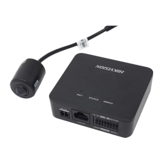
Network Covert Camera·Quick Start Guide 1.1.2 Type II Camera General Appearance Type II Camera General Appearance Figure 1-2 Description of the General Appearance Table 1-2 Description Main unit LINK: network indicator STATUS: status indicator POWER: power indicator... -
Page 16: Type Iii Camera General Appearance
Network Covert Camera·Quick Start Guide 1.1.3 Type III Camera General Appearance Type III Camera General Appearance Figure 1-3 Description of the General Appearance Table 1-3 Description Main unit Solid red: Power-on POWER Indicator LED Unlit: Power-off Solid green: The camera works properly. -
Page 17: Front Panel
Network Covert Camera·Quick Start Guide Description Flashing amber: Network properly LINK Indicator connected. Unlit: Network disconnected. Front Panel 1.2.1 Type I Covert Camera Front Panel The Type I covert camera equips with three types of front panel, as shown in Figure 1-4, Figure 1-5, and Figure 1-6. VIN1 AUDIO AUDIO... - Page 18 Network Covert Camera·Quick Start Guide VIN1 AUDIO AUDIO The Type B Front Panel Figure 1-5 VIN1 VIN2 AUDIO AUDIO The Type C Front Panel Figure 1-6 Description of the Front Panel Table 1-4 Description Audio input Audio output...
-
Page 19: Type Ii Covert Camera Front Panel
Network Covert Camera·Quick Start Guide RJ-12 video input interface(s) Memory card slot 1.2.2 Type II Covert Camera Front Panel Type II Camera Front Panel Figure 1-7 Description of the Front Panel Table 1-5 Description Power Input: 12 V DC Network interface ... -
Page 20: Type Iii Covert Camera Front Panel
Network Covert Camera·Quick Start Guide 1.2.3 Type III Covert Camera Front Panel The front panel of the Type III covert camera is shown in Figure 1-8. The Type B Front Panel Figure 1-8 Description of the Front Panel Table 1-6 Description 12 V DC M8 aviation plug LAN interface... -
Page 21: Type Ii Covert Camera Rear Panel
Network Covert Camera·Quick Start Guide LAN(PoE) RXD TXD GND IN1 1B 1A DC 12V RESET Type I Covert Camera Rear Panel Figure 1-9 Description of the Type I Covert Camera Rear Panel Table 1-7 Description Reset Power input RS-232 and alarm input and output interfaces Ethernet interface with PoE function 1.3.2 Type II Covert Camera Rear Panel... -
Page 22: Type Iii Covert Camera Rear Panel
Network Covert Camera·Quick Start Guide Type II Covert Camera Rear Panel Figure 1-10 RESET button VIN interface (Connect SMA Interface) USB interface* Memory card slot Note: Only certain models have USB interface. 1.3.3 Type III Covert Camera Rear Panel The rear panel of the Type III covert camera is shown in Figure 1-11. -
Page 23: Sensor Units
Network Covert Camera·Quick Start Guide Type II Covert Camera Rear Panel Figure 1-11 Description of the Covert Camera Rear Panel Table 1-8 Description Power input: 12 VDC AUDIO: connect OUT and GND terminals, connect IN and GND terminals Reset VIN interface Sensor Units The different covert camera model is equipped with four different types of sensor unit, including block-shaped sensor unit, cylindrical... - Page 24 Network Covert Camera·Quick Start Guide Block-Shaped Sensor Unit Figure 1-12 Description of the Block-Shaped Sensor Unit Table 1-9 Description Block-Shaped sensor unit Decorative cover Straight mounting bracket Video output cable with RJ-12 interface...
- Page 25 Network Covert Camera·Quick Start Guide Type II: Cylindrical Sensor Unit Cylindrical Sensor Unit Figure 1-13 Description of the Block-Shaped Sensor Unit Table 1-10 Description Cylindrical Sensor Unit Video output cable with RJ-12 interface Round Rail Mounting Bracket...
- Page 26 Network Covert Camera·Quick Start Guide Type III: Tube Lens Tube Lens Figure 1-14 Description of the Tube Lens Table 1-11 Description Tube Lens Ceiling Mounting Bracket Video output cable with RJ-12 interface...
- Page 27 Network Covert Camera·Quick Start Guide Type IV: Ball-Shaped Sensor Unit The ball-shaped sensor unit has two models with different communication interfaces, the RJ-12 interface and M12 interface. Ball-Shaped Sensor Unit and Included Bracket Figure 1-15...
- Page 28 Network Covert Camera·Quick Start Guide Description of Ball-Shaped Sensor Unit Table 1-12 Description Ball-Shaped Sensor Unit Video output cable with RJ-12 interface Video out cable with M12 aviation plug Bracket Included...
-
Page 29: Installation
Network Covert Camera·Quick Start Guide 2 Installation Before you start: ● Make sure the device in the package is in good condition and all the assembly parts are included. ● The standard power supply is 12 VDC or PoE, please make sure your power supply matches with your camera. - Page 30 Network Covert Camera·Quick Start Guide Secure the Mounting Rail Figure 2-1 Secure the bracket on the rear surface of the main unit with corresponding screws. Secure Bracket onto Main Unit Figure 2-2 Do not upside down the main unit when you fasten the bracket. Hang the main unit together with the bracket to the mounting rail and complete the installation.
-
Page 31: Installing Type Ii Covert Camera Unit
Network Covert Camera·Quick Start Guide Hang the Main Unit Figure 2-3 2.1.2 Installing Type II Covert Camera Unit Steps: 1. Secure the mounting rail onto the installation surface with the supplied PA3 × 25 screws. Secure the Mounting Rail Figure 2-4 2. -
Page 32: Installing Type Iii Covert Camera Unit
Network Covert Camera·Quick Start Guide Secure Bracket onto Main Unit Figure 2-5 Do not upside down the main unit when you fasten the bracket. 3. Hang the main unit together with the bracket to the mounting rail and complete the installation. 2.1.3 Installing Type III Covert Camera Unit Steps: Secure the bracket on the rear surface of the main unit with four... -
Page 33: Installing The Block-Shaped Sensor Unit
Network Covert Camera·Quick Start Guide Secure Bracket onto Main Unit Figure 2-6 Secure the bracket onto the installation surface with the supplied screws. Secure the Mounting Rail Figure 2-7 Installing the Block-Shaped Sensor Unit This series of camera support concealed mounting and exposed mounting with a decorative cover. - Page 34 Network Covert Camera·Quick Start Guide Please make sure that the mounting surface is suitable for adhesive pasting. Steps: 1. Drill on the mounting surface, as shown in Figure 2-8. Drill on the Surface Make sure the drilling hole is big enough for the camera lens. 2.
- Page 35 Network Covert Camera·Quick Start Guide Paste the Bracket 3. Install the block-shaped sensor unit into the bracket and make it to be buckled. 4. Tighten the fastening screw on the top of the bracket. Insert the Block-shaped Sensor Unit...
-
Page 36: Exposed Mounting
Network Covert Camera·Quick Start Guide 2.2.2 Exposed Mounting Steps: Fix the Block-shaped sensor unit on the mounting surface with screws, as shown in Figure 2-11. Fix the Block-shaped Sensor Unit For cement surface mounting, you need to use the expansion screw to fix the camera. -
Page 37: Mounting With Pole-Shaped Bracket
Network Covert Camera·Quick Start Guide 5. Shield the sensor unit with the decorative cover. As shown in Figure 2-12. Hood the Cover 2.2.3 Mounting with Pole-Shaped Bracket If you purchase the camera with a pole-shaped mounting bracket, follow the steps to complete installation of the lens and the bracket. Lens Bracket Cover Base... - Page 38 Network Covert Camera·Quick Start Guide Steps: 1. Fit the lens and the lens cable into the lens bracket as shown below. Lens Bracket Lens Cable Fit Lens and Lens Cable into Lens Bracket 2. Make a mark at a height of 1.83m (6ft.) on wall (or other desired mounting position).
- Page 39 Network Covert Camera·Quick Start Guide 1.83m 1.83m (6ft) (6ft) 1.83m (6ft) Marking for Installation 3. Install the first expansion screw loosely and hang the bracket base on the screw.
- Page 40 Network Covert Camera·Quick Start Guide First Expansion Screw 1.83m (6ft) Hang the Bracket Base 4. Plan and prepare cable routing. This bracket supports cable routing through wall and on surface, select one way according to your actual needs. If you choose to route cable through wall, drill a cable hole according to the size and height of cable hole on the base.
- Page 41 Network Covert Camera·Quick Start Guide 1.83m (6ft) Cable Hole Cable Holes Route cable on surface Route cable through wall Plan Cable Routing 5. Route cable and fit the lens bracket into the base. Use a screw to secure the lens bracket. See Figure 2-18.
- Page 42 Network Covert Camera·Quick Start Guide Install and Secure Lens Bracket 6. Loosely screw the thumbscrew to the base. Adjust the panning position of the lens, and tighten the thumbscrew. Pan: -15° to +15° Thumbscrew Install Thumbscrew and Adjust Panning Position...
- Page 43 Network Covert Camera·Quick Start Guide 7. Screw the top cover to the base. Top Cover 1.83m 1.83m (6ft) (6ft) Install Top Cover 8. Install the second expansion screw. Tighten the first expansion screw. See Figure 2-21. 9. Peel off protective films on both side of the decorative cover. Slide the decorative cover in the base.
- Page 44 Network Covert Camera·Quick Start Guide First Expansion 1.83m Screw (6ft) Second Expansion Screw Secure Base on Peel off Wall Protective Films and Slide the Decorative Cover in the Base...
-
Page 45: Installing The Cylindrical Sensor Unit
Network Covert Camera·Quick Start Guide 10. Screw the bottom cover to the base. Install Bottom Cover Installing the Cylindrical Sensor Unit This series of camera only support concealed mounting. Please make sure that the mounting surface is suitable for adhesive pasting. - Page 46 Network Covert Camera·Quick Start Guide Drill on the Surface Make sure that the drilling hole is big enough for the camera lens. 2. Remove a side of the adhesive tape on the bracket. Paste the bracket on the mounting surface with aligning with the drilling hole.
-
Page 47: Installing The Tube Lens
Network Covert Camera·Quick Start Guide 4. Turn the locking sleeve to fix the sensor. Install the Cylindrical Sensor Installing the Tube Lens Steps: 1. Fix the mounting base of the bracket to the ceiling with the supplied screws. Fix the Ceiling Mounting Bracket... - Page 48 Network Covert Camera·Quick Start Guide 2. Hood the bracket cover to the mounting base. Hood the Bracket Cover 3. Screw the bracket to the mounting base. Screw the Bracket...
- Page 49 Network Covert Camera·Quick Start Guide Another shorter bracket is also selectable; please select the bracket according to your demand. 4. Loop the tube lens with the loop of the bracket, and tighten it with the supplied screw. As shown in Figure 2-30. Loop the Tube Lens 5.
- Page 50 Network Covert Camera·Quick Start Guide Install the Tube Lens to the Bracket 6. Loosen the knob to adjust the surveillance angle, and then tighten the lock nut to complete the installation. Figure 2-32 Complete the Installation...
-
Page 51: Installing The Ball-Shaped Sensor Unit
Network Covert Camera·Quick Start Guide Installing the Ball-Shaped Sensor Unit 2.5.1 Mounting with the Included Bracket Steps: 1. Paste the drill template to the desired mounting place. Drill two screw holes and a hole for routing cable according to the drill template. - Page 52 Network Covert Camera·Quick Start Guide Figure 2-34 Fix the Mounting Bracket on Ceiling or on Wall 3. Place the camera in the bracket cover. ② Camera ① Screw ③ Bracket Cover Figure 2-35 Place the Camera in Bracket Cover...
- Page 53 Network Covert Camera·Quick Start Guide 4. Get the wedge on the bracket cover stuck in the slot of the mounting base, close the cover, and screw the bracket cover on the mounting base loosely. Wedge Slot Figure 2-36 Install the Camera and Bracket Cover...
- Page 54 Network Covert Camera·Quick Start Guide 5. Adjust the surveillance angle. Stick the supplied plastic ring in the camera Connect the cables and power on the camera to view the image. Hold and move the plastic ring to adjust the panning, tilting, and rotating position to desired place.
- Page 55 Network Covert Camera·Quick Start Guide 6. Tighten the screw on the bracket cover. Figure 2-38 Tighten the Screw 2.5.2 Mounting with a Incline Bracket Before you start: There is no incline bracket included in the package. If you choose this mounting type, you need to provide a bracket before starting.
- Page 56 Network Covert Camera·Quick Start Guide Figure 2-39 Drill Template 2. Route the camera cable through the mounting base of the incline bracket. And fix the camera to the mounting base with the fixing ring and screw. The screw should be installed loosely to leave some space for view angle adjustment.
- Page 57 Network Covert Camera·Quick Start Guide Mounting Base Camera Fixing Ring Screw Figure 2-40 Fix the Camera to Mounting Base 3. Install the incline bracket with camera on the wall or ceiling with supplied screws. Cable Hole Ceiling Wall Cable Hole Screws Screws Figure 2-41 Fix the Camera and Mounting Base to Wall or Ceiling...
- Page 58 Network Covert Camera·Quick Start Guide 5. Tighten the screw on fixing ring. 6. Install the incline bracket cover. Mounting Base Ceiling Incline Bracket Cover Mounting Wall Base Incline Bracket Cover Figure 2-42 Install the Incline Bracket Cover...
- Page 59 Network Covert Camera·Quick Start Guide 3 Activate and Access Network Camera Scan the QR code to get Activate and Access Camera. Note that mobile data charges may apply if Wi-Fi is unavailable.
- Page 60 UD19466B...
Need help?
Do you have a question about the DS-2CD6425G0 Series and is the answer not in the manual?
Questions and answers