Table of Contents
Advertisement
Advertisement
Table of Contents

Related Manuals for Rinstrum C530


Summary of Contents for Rinstrum C530
- Page 1 C500 Series Digital Indicator Reference Manual...
- Page 2 Pty Ltd. Disclaimer Rinstrum Pty Ltd reserves the right to make changes to the products contained in this manual in order to improve design, performance or reliability. The information in this manual is believed to be accurate in all respects at the time of publication, but is subject to change without notice. Rinstrum Pty Ltd assumes no responsibility for any errors or omissions and disclaims responsibility for any consequences resulting from the use of the information provided herein.
-
Page 3: Table Of Contents
Contents 1 Introduction 2 Installation 2.1 Introduction ..........2.2 Environmental Conditions . - Page 4 8.2 Formats ..........8.3 Custom Format Tokens .
- Page 5 17.5 Locking ..........17.6 Totalising .
-
Page 6: Introduction
(A/D) converter to ensure extremely fast and accurate weight readings. This advanced technology allows the C520 and C530 to be configured for up to 100,000 divisions with up to 100 A/D conversions per second. The units have extended sensitivity adjustment which can handle scales with outputs 0.2-5.0mV/V for full range. -
Page 7: Installation
Installation Introduction The C520 can be used as either a desk-top or panel-mount instrument. The C530 is intended for installation in electronics cabinets. The C500 series contains precision electronics and must not be subject to shock, excessive vibration, or extremes of temperature, either before or after installation. The operating environment must fall within the allowed temperature range and humidity. - Page 8 C530 Surface Mount The C530 can be attached to a surface using the four mounting holes. 1. Use four M4 bolts, or four #6 screws to attach the C530 to the mounting surface as shown below. 2.3.3 C530 DIN Rail Mounting The C530 can be attached to a DIN rail using the optional DIN rail mounting kit: 1.
-
Page 9: Power Connection
Power Connection The C500 series can be powered from DC or AC supplies. 2.4.1 DC Power The C500 series requires a 12-24VDC power supply. The supply need not be regulated, provided that it is free of excessive electrical noise and sudden transients. The C500 series can operate from good quality plug-packs of sufficient capacity to drive both the indicator and the loadcells. -
Page 10: Loadcell Connection
Loadcell Connection 2.5.1 Overview The C500 series can drive any number of full bridge strain gauge loadcells up to the equivalent of 16 x 350 ohm cells (21 ohm load). The span range of the loadcell outputs (the change of signal from the loadcells between zero load and full gross load) must be within the range of 0.2 to 5.0 mV/V. -
Page 11: Ex-I Loadcell Connection
2.5.2 Cable When wiring loadcells use only high quality shielded multi-core cable. The cable should be run as far away from any other cabling as possible (minimum separation distance 150mm). Do not bundle loadcell cables with power or control switching cables as interference can trigger display instability, and cause unreliable operation. The loadcell shield must be installed so as to connect electrically with the metal shell of the DB9 plug or screw terminal shield connection in order for the C500 series to provide its full EMC resistance. -
Page 12: Optical Communications
2.6.1 Non-trade Limits C520/C530 with zener barrier SD01 (Input signal 0,2 µV/e, divisions 3000d, loadcells 2mV/V) No of loadcells Minimum yield of the loadcells 350 Ω... -
Page 13: Db9 Serial Port 1 Connection (C520 Only)
The PC end of the cable is a standard USB connector. The instrument end of the cable attaches to the left side of the indicator display, or the rear of the indicator as shown below. Warning! The optical coupling head contains a strong magnet and should not be placed near any magnetic storage media (eg. -
Page 14: Db9 Serial Port 2 Connection (C520 Only)
2.8.4 RS485/RS422 Bus Connection Pins 6 to 9 of serial 1 are connected directly to pins 6 to 9 of the Serial 2 connector. This provides for convenient implementation of multi-drop RS422 or RS485 communications. RA 6 SERIAL RB 7 RS485/RS422 TA 8 HOST... - Page 15 Warning! Do not connect the USB host port to another USB host port. It is possible to purchase USB A Male to USB A Male cables as shown in the picture below that permit such a connection. Making such a connection will damage the indicator and PC, voiding the warranty on both devices.
-
Page 16: User Interface
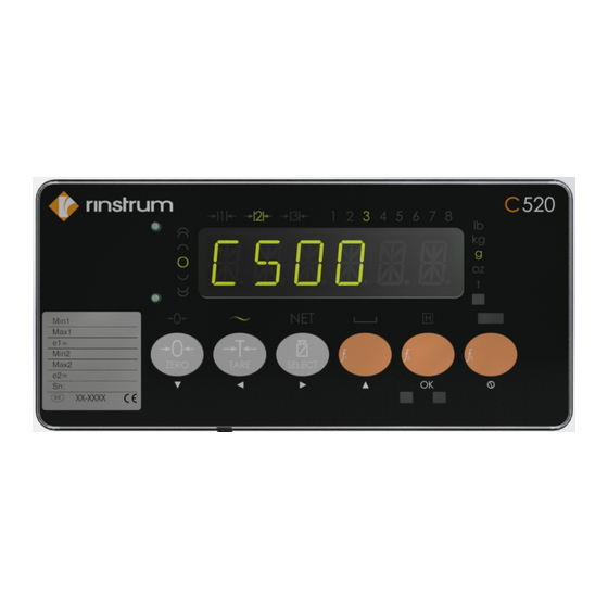
User Interface General The front panel of the C520 has a six digit LED display and a 6 key keypad. A cover on the rear allows access to a hidden key which can be used to enter full digital setup and calibration. The diagram below shows the main elements of the front panel. -
Page 17: Keys
Lit when the displayed reading is within of a division of true zero. Lit when the displayed reading is in motion. Lit when the displayed reading represents net weight. Lit when the displayed reading is within the zero range. Lit when the display reading has been held. Ranges 1 and 2 (multiple range/interval modes only). - Page 18 3.3.4 Function 1, 2 & 3 Keys Normal function Configurable Configured in setup. ƒ ƒ ƒ Long press function Depends on configured normal func- tion. 3.3.5 Rear Setup Key Normal function Setup Enter and exit full setup. See Section 5.1.4. C500-600-2.0.3...
-
Page 19: Licensing
The C500 series uses licence codes to activate software packages installed on the indicator. All packages with names in the C500-K5xx and L9xx-5xx range will require a license to be entered. Licence codes are unique for each indicator and can be acquired from the nearest Rinstrum office. Unlicensed Packages If a package requiring a license is installed but not yet licensed, a message like “C500”... -
Page 20: Setup
Setup General Information 5.1.1 Introduction Setup and calibration is carried out entirely from the front panel using the setup functions on the control keys. There are 3 types of setup: ˆ Full setup: Allows access to all setup parameters, including calibration. ˆ... - Page 21 2. If a passcode has been set: Use the Gross/net and Print keys to enter the passcode. Press the OK key to confirm the passcode. 5.1.4 Navigation The setup menus are organised in a tree structure. Main menus are called groups. Groups contain sub-groups and items.
- Page 22 5.1.5 Editing Option Items Some settings allow the choice of an option from a predefined list of options. Examples are BUILD:DP or OPTION:USE. To show/edit: ˆ Press the OK key to show the current setting ˆ Press the up or down keys until the correct setting is shown ˆ...
-
Page 23: Build: Scale Build Menu
ˆ To enter the ASCII value, use the left and right keys to change the selected digit and the up and down keys to change that digit ˆ Use the OK key to advance to the next character in the string ˆ... - Page 24 Range 1 verification in- Sets the minimum verification interval of the scale (as dis- terval played). If BUILD:TYPE=DUAL I or BUILD:TYPE=DUAL R, it sets minimum verification interval of the 1st range. Options are: ˆ 1(def) ˆ 2 ˆ 5 ˆ 10 ˆ...
-
Page 25: Option: Scale Options Menu
OPTION: Scale Options Menu Items within this group set various weighing options for the scale. Changes of some items will affect certification. Items Name Description Scale trade use Set whether the scale is for trade use. Options are: ˆ OIML: Scale operation is not restricted by OIML or NTEP ˆ... - Page 26 Auto-zero on start-up AUTO.Z Enable and initial zero on start. The amount of weight that can be zeroed is limited to 10% of scale capacity. Options are: ˆ OFF(def) ˆ ON Zero tracking Z.TRAC Enable zero tracking. Set in divisions per time period. For example, 0.5-1.0 means that zero tracking will cancel no more than 0.5 divisions in 1 second whilst in the zero band.
-
Page 27: Cal: Scale Calibration Menu
CAL: Scale Calibration Menu Items in this group are used for scale calibration. See Section 7. Items Name Description Zero calibration ZERO Perform a zero calibration Span calibration SPAN Perform a span calibration Linearity calibration ED.LIN Perform a linearity calibration Clear linearity points CLR.LIN View/clear linearity points... -
Page 28: Serial: Serial Communications Menu
ˆ PRINT: Enable printing ˆ SINGLE: Transmit once (see also Section 17.7) ˆ NET: Rinstrum network protocol (see Sections 18 and 21) ˆ MB.LGCY: 5000 Modbus ASCII legacy protocol (see Section 22) ˆ MB.ASCI: Fully featured Modbus ASCII protocol (see Section 19) ˆ... - Page 29 ˆ AUTO.HI: Auto transmit at the sync frequency ˆ PRINT: Enable printing ˆ SINGLE: Transmit once (see also Section 17.7) ˆ NET: Rinstrum network protocol (see Sections 18 and 21) ˆ MB.LGCY: 5000 Modbus ASCII legacy protocol (see Section 22) Destination IP DST.IP...
- Page 30 UDP listen port PORT Sets the port on which the indicator listens for commands. Replies are sent to the last IP:port that a command was received from. On non- network ports (AUTO.LO, etc), the receving end should send an empty UDP packet to the indicator to initiate sending.
- Page 31 Modbus TCP PORT Set the TCP port that listens for Modbus connections. Default: 502 Port 32bit Endian ENDIAN This sets the endianness for 32bit Modbus registers. The Modbus speci- fication does not specify endian for values larger than 16bits. This setting does not swap the endian for 16bit values. These are fixed. Options are: ˆ...
-
Page 32: Eth.net: Ethernet Menu
ETH.NET: Ethernet Menu Items within this group set the Ethernet and IP parameters. Items Name Description DHCP enable DHCP Set whether IP setup is obtained via DHCP. Options are: ˆ OFF ˆ ON (default) IP address View or set the IP address. Displayed as nnn.nnn.nnn.nnn (eg 192.168.1.254). -
Page 33: Spec: Special Settings Menu
SPEC: Special Settings Menu Items within this Group set the security codes, key locking and special modes. Items Name Description Safe setup passcode SAFE.PC Passcode required to enter safe setup. Set to 0 to allow free access. Default is 0. Full setup passcode FULL.PC Passcode required to enter full setup. - Page 34 Operation of the IN.FN Set the function of the remote inputs (see Section 17). Options external inputs are: ˆ NONE Remote Key 1 IN.FN.1 ˆ ZERO Remote Key 2 IN.FN.2 ˆ TARE Remote Key 3 IN.FN.3 ˆ GROSS Remote Key 4 IN.FN.4 ˆ...
-
Page 35: Test: Test Menu
TEST: Test Menu Items within this group are used for testing. Items Name Description mV/V test mode SCALE Show the loadcell signal in mV/V. In trade mode this test is only available for 5 seconds. Test IO: 1 to 4 IO-1.4 Test IO by checking the value of inputs and setting outputs Test IO: 5 to 8... -
Page 36: Set.pts: Setpoints Menu
SET.PTS: Setpoints Menu This section is used to set all of the operational logic of the setpoint system, as well as provide for the entry of secure setpoint target and inflight values. Items Name Description General General setpoint settings Jog on time JOG.ON Job on time in milliseconds. - Page 37 Alarm ALARM Setpoint alarm. Options are: ˆ OFF(def): no alarm. ˆ SINGLE: Single beep alarm. ˆ DOUBLE: Double beep alarm. ˆ CONT.: Continuous beeping alarm. ˆ FLASH: Flash display alarm. Output timing TIMING Output timing. Options are: ˆ LEVEL: Output is active when setpoint is active and reset is not active (default) ˆ...
-
Page 38: Analog: Analog Output Menu
5.10 ANALOG: Analog Output Menu Items within this menu set the options for the optional analog output module. Items Name Description Source SOURCE Select the reading source. Options are: ˆ GROSS: Gross weight ˆ NET: Net weight ˆ DISP(def): Displayed weight (gross or net) ˆ... -
Page 39: Clock: Clock Menu
5.11 CLOCK: Clock Menu This menu is used to set the clock/calendar and QA options. Items Name Description Time set TIME Set the time in the format HH.MM, where: ˆ HH: Hours (00 - 23) ˆ MM: Minutes (00 - 59) Date set DATE Set the current date in EU format (DD.MM.YY), where:... -
Page 40: File: File Menu
SAV.DBG Export debug information to disk. This file provides use- to USB disk ful information to Rinstrum when trying to solve installa- tion and setup problems. The file will be saved in the root directory and be named as follows: <model> <serial number>... -
Page 41: Dsd: Digital Storage Device Menu
5.13 DSD: Digital Storage Device Menu This group is used for digital storage device options. Items Name Description DSD Enable ENABLE Enables and disables the DSD. Options are: ˆ OFF(def): Traceable weights are not stored in the DSD ˆ ON: Traceable weights are stored in the DSD Note After enabling the DSD for the first time, it is necessary to initialise the DSD before use using... -
Page 42: Chg.log: Changelog Menu
5.14 CHG.LOG: Changelog Menu This group is used for change log options. Items Name Description Changelog Status STATUS Displays the percent full of the change log. Clear Changelog CLEAR Clear the changelog. All records will be lost. An entry will be made in the changelog to indicate it has been cleared. -
Page 43: Factry: Factory Menu
5.15 FACTRY: Factory menu This group is used for factory options. Items Name Description Restore Factory default DEFLT Restores settings to factory defaults (except calibration set- tings). Printout of the indica- PRN.CFG Print all settings to the connected printer. tor settings See Section 5.12 FILE:SAV.SET for saving this information to a disk. -
Page 44: Operator Menus
Operator Menus The operator menus provide access to some settings typically used by operators. These do not require access to safe or full setup. Items Name Description Setpoint Targets TARGET The target menu displays the sepoint targets for active setpoints only. Inactive and other setpoint types are hidden. - Page 45 Subnet mask MASK View the currently assigned subnet mask. Gateway address GATE.W View the currently assigned default gateway ad- dress. DNS address View the currently assigned DNS server address. Host name HST.NAM View the indicator hostname. MAC address View the indicator Ethernet MAC address in hexadecimal.
-
Page 46: Calibration And Trade
Calibration and Trade Introduction and Warnings The calibration of the C500 series indicators are fully digital. The calibration results are stored in permanent memory for use each time the unit is powered up. Some of the menu settings affect calibration. The BUILD settings must be set before calibration. Changing these settings after calibration may alter the calibration. - Page 47 ˆ The signal resolution = 5mV / 1000 divisions = 5 µV/division 7.2.2 Dual Interval and Dual Range Operation The indicator provides single range, dual interval and dual range modes. In non-trade operation, up to 100,000 divisions are available so it is rare for the precision of the displayed reading to be a problem. However in trade applications where the number of divisions that can be legally displayed is limited, the use of dual interval or dual range operation allows greater precision in the displayed readings without exceeding the maximum number of graduations available in the certification of the loadcell.
- Page 48 FIR filter introduces a delay of 3 samples to the step response. So for a SYNC frequency of 50Hz (i.e. readings every 20 milliseconds) there is a delay of 60 milliseconds between a weight change and the final weight reading (before averaging is applied). Digital Averaging: ˆ...
-
Page 49: Cal:zero Zero Calibration Routine
7.2.7 Trade versus Industrial Mode The indicator may be operated in trade or industrial mode. The differences in operation are: Operation Trade mode Industrial mode Underload Below zero range setting -105% of fullscale Overload Fullscale + 9 divisions 105% of fullscale Tare Tare values must be >... -
Page 50: Linearisation
Linearisation Up to 10 linearisation points can be set independently anywhere in the operating range of the scale. Unused points may be cleared. Warning! Linearisation changes the signal resolution. If this is close to the limit, it should be checked. 7.5.1 CAL:ED.LIN Add Linearity Point 1. -
Page 51: Cal:fac.cal Factory Calibration
5. Press the cancel key to exit the direct zero calibration and return to the menu. 6. Press the tare key to show the CAL:DIR.SPN setting (displays DIR.SPN). 7. Press the OK key. The display will show the current weight. 8. -
Page 52: Automatic Weight Output
Automatic Weight Output Introduction The automatic output is normally used to drive remote displays, dedicated computer connections or PLCs. The output generates a simple weight message at predefined intervals. Formats There are 6 automatic output formats, including one custom format. The start and end characters of the format strings can be set (even for the standard formats) in the SERIAL:AUT.OPT menu. - Page 53 where: ˆ Sign (1 character): SPACE or ‘-’ ˆ Weight (7 characters): The weight in 7 characters with decimal point and leading spaces. ˆ S1 (1 character) = ‘G’, ‘N’, ‘U’, ‘O’ or ‘E’ for Gross, Net, Underload, Overload and Error. ˆ...
-
Page 54: Custom Format Tokens
Custom Format Tokens 8.3.1 Formatting C500-600-2.0.3... - Page 55 Token Description Default 5 character weight 6 character weight 7 character weight 8 character weight 9 character weight No fixed length field for weight data No sign character sent Sign character send as ‘ ’ for positive and ‘-’ for negative Sign character send as ‘+’...
- Page 56 Send time in format: hh:mm:ss Send Date in format: dd/mm/yyyy C500-600-2.0.3...
-
Page 57: Printing
Printing Overview Four print formats are available. They are based on a 20 or 40 column width printer and may be printed on a 20 or 40 column tally roll serial printer, or a 80 column dot matrix serial printer. Printing may be triggered manually by a configured print key or automatically (auto-printing). -
Page 58: Custom Ticket Format
used. 9.2.1 Example The following table shows the coded entry for “JOE’S FRUIT & VEG”. The ‘J’ would be entered as 1.08.074 for line 1, column 8, ASCII Code 74. ’ & Custom Ticket Format Custom ticket formats can be entered in the SERIAL:PRN.OPT:TIC.FMT setting. Up to 250 characters can be entered to define the exact style of ticket printout. -
Page 59: Ascii Codes
Print lines 4-6 of the header w/o CRLF Print the number of Columns of SPACE specified by the Printer Space settings Print Date Time field: hh:mm:ss dd:mm:yyy Print End of Line : literally prints CRLF (ASCII 013, 010) Print End of Line (CRLF) followed by 131 (print number of columns of space) Print Gross Weight: “weight(7) units(3) G”... -
Page 60: Usb Interface
USB Interface 10.1 Device Interface The USB device interface allows the indicator to be connected to a host PC as a slave device. The indicator will appear as a virtual serial port device to the PC. This requires a Windows driver to be installed which is supplied with the C500 viewer software. - Page 61 Warning! Power off the indicator before disconnecting a USB serial port from the USB host port. C500-600-2.0.3...
-
Page 62: Change Log
Change Log 11.1 Introduction The indicator contains a change log that records trade significant events. These include changes to trade relevant settings, creation and clearing of the change log and trade relevant firmware upgrades. Only trade relevant settings are stored in the change log. The change log records the following information about each change: ˆ... -
Page 63: Digital Storage Device (Dsd)
Digital Storage Device (DSD) 12.1 Introduction The indicator contains a Digital Storage Device (DSD) to record traceable readings. The DSD records the following information about each entry: ˆ The print ID ˆ The weight reading ˆ The tare weight ˆ The date and time 12.2 Format and Capacity The DSD is stored in a binary format internally. - Page 64 Print ID, Reading, Units, Status, Tare Weight, Units, Status, Valid, Timestamp 3, 223.5, kg, G, 223.5, kg, T, Yes, 2012-06-13 05:43:47 C500-600-2.0.3...
-
Page 65: Alibi Application
Alibi Application 13.1 Introduction The Alibi application is part of the trade approval and makes it possible to verify scale readings, view DSD and change log entries. It can be accessed from the main application by a long press of the Select key, and then selecting Alibi from the list. -
Page 66: Dsd And Change Log Viewer Modes
13.4 DSD and Change log Viewer Modes The following keys apply in DSD and Change log Viewer modes: Short Press Prev record Go to the previous record Long press First record Go to the first (oldest) record Short Press Next record Go to the next record Long press Last record... -
Page 67: Ethernet Interface
Ethernet Interface 14.1 Overview The Ethernet interface provides connectivity via a standard 802.3 network. The indicator contains a 100MBit Ethernet interface. This interface allows connectivity to other networked devices, such as PCs. The indicator IP network settings can be configured from the menus under ETH.NET. See Section 5.6. Fixed or DHCP assigned addresses can be used. - Page 68 (d) Setting the type to off, or setting the source port to 0 disables the socket. Warning! Note that UDP is an un-reliable protocol. This means that there is no guarantee of packet delivery or packet arrival order. Your client will need to deal with this. Alternatively, use a TCP connection.
-
Page 69: Accessory Modules
Accessory Modules 15.1 Introduction The indicator can be expanded by the installation of optional accessory modules. A range of modules are available: ˆ M5401 Analogue output module ˆ M5301 8 I/O module ˆ M5101 AC power module ˆ M5201 RS232 full duplex / RS232 transmit only serial communications module ˆ... -
Page 70: Setpoints
Setpoints 16.1 Introduction The C500 series has 8 setpoints. The status of the setpoints is shown on the display (see Section 3.2). An optional output driver module can be fitted to allow the setpoints to drive external devices. The lamps then show the status of the output drivers. Each of the setpoints provides a comparator function that can be modified in the digital setup for switching direction, hysteresis, logic, etc. - Page 71 Target Flight Hysteresis Weight Time RESET Input LEVEL EDGE Off PULSE LATCH Figure 1: Comparison of output timing on Over setpoint Note that the outputs revert to the off state when the instrument SETUP menus are active. ˆ ALARM: Select what alarm response is triggered when the setpoint is active. –...
-
Page 72: Over, Under, Weigh In And Weigh Out Setpoints
the hysteresis value and the reset input is not currently active. – EDGE: The setpoint becomes active when the weight goes over the target. The setpoint becomes inactive when the weight goes below the hysteresis value or the reset input becomes active. –... -
Page 73: Status Based Setpoint Types
ˆ FLIGHT: Set the amount of material that is in-flight. This is used to turn the output off before the target it reached so it does not overshoot. ˆ LOCK: Set if the target and flight values will be locked from editing in the OPER menu. ˆ... -
Page 74: Remote Input Functions
Remote Input Functions 17.1 Introduction The F1, F2 and F3 keys on the front of the C520 can be set to a variety of functions depending on the application. There are also 8 external key inputs (connected to the optional IO modules). 17.2 Functions Function... -
Page 75: Locking
17.5 Locking When this input is active, all keys including the remote keys, are blocked. This may be used with a keylock switch to lock the instrument when not in use. 17.6 Totalising Totalising keys are only available if SERIAL:PRN.OPT:PRNT.TP=TOTAL or SERIAL:PRN.OPT:PRNT.TP=A.TOTAL. Add-to-total is performed by the print function before printing. -
Page 76: Thumbwheel Io Selection Of Printer Text Line
17.8 Thumbwheel IO selection of printer text line This allows a thumbwheel connected to several IO to select one of nine text strings to be printed via the print token 152 (see Section 9.4). The text to be printed can be set using the TXT command (see Section 21.3.52). All IOs configured for thumbwheel are combined together to select the string from lowest IO giving the least significant bit to highest IO giving the most significant bit. -
Page 77: Network Communications
Network Communications 18.1 Introduction The RS-232, RS-485, Ethernet and the optical communications can be used for networking. Warning: The calibration counter is incremented when the calibration related settings are changed. This means that calibration via a serial port cannot be carried out without affecting the certification of a trade installation. Serial communications parameters like BAUD, PARITY, etc for the RS232 or RS485 serial ports are setup in the HDWARE menu. - Page 78 Command Description Read Type Read the register type. Value Description INT8: Signed 8 bit value UINT8: Unsigned 8 bit value INT16: Signed 16 bit value UINT16: Unsigned 16 bit value INT32: Signed 32 bit value UINT32: Unsigned 32 bit value STRING: Null terminated string WEIGHT: Weight value (weight, status and units) EXECUTE: Perform an action (eg tare)
- Page 79 Note The hexadecimal codes are combined in the fields described above when multiple options are active at the same time. For example an error response message from instrument address 5 would have an ADDR code of C5 + 40 + 05 18.2.2 Termination Message termination is possible in two ways.
-
Page 80: Rincmd Examples
Error Code Error Description 0500 Write Error 0501 Permission error You do not have permission to write to this register. 0502 Unknown type error Internal error: Register type is not known to RinCmd. 0503 No type data error Internal error: Unable to write to the registers data structure. 0504 Command error The CMD is not valid for this register type. - Page 81 Read Gross Weight COMMAND A: COMMAND A: Read Gross Weight (Register 0026 20050026:; ADDR = 20 : Reply required from any instrument CMD = 05 : Read Literal REG = 0026 : Gross Weight RESPONSE A: RESPONSE A: 81110026: 100 kg G; Same response from instrument #1 but in literal format.
- Page 82 Zero Scale COMMAND A: COMMAND A: Execute the zero register (Register 0300 21100300:; ADDR = 21 : Reply required from instrument #1 CMD = 10 : Execute REG = 0300 : Zero function RESPONSE A: RESPONSE A: 81100300:00000006; Instrument #1 reports error 6 (scale is in motion). COMMAND B: COMMAND B: Execute the zero register (Register 0300...
-
Page 83: Rincmd Registers
COMMAND D: COMMAND D: Stop streaming (Register 0040 21100040:0; ADDR = 21 : Reply required from instrument #1 CMD = 10 : Execute REG = 0040 : Streaming start register DATA = 0: Stop streaming RESPONSE D: RESPONSE D: 81100040:0000; Instrument #1 will stop streaming on change. - Page 84 Name Address Type Description System status uint32 Read current system status. Bits are as 0021 follows: 0-7: Last calibration result 8: Reserved 9: Scale is in Net mode 10: Scale is within the zero band 11: Scale is within center of zero 12: Scale is in motion 13: Calibration is in progress 14: Menus are active...
- Page 85 Name Address Type Description Traceable date: second uint8 Second that the traceable weight was 003C acquired Stream Set 1 Data stream Returns a block of data which is selected 0040 in Stream Register 1-5. Use a read command to read a single set of data.
- Page 86 Name Address Type Description User String 3 string User readable/writable string 3 0092 User String 4 string User readable/writable string 4 0093 User String 5 string User readable/writable string 5 0094 Display Top Left string Write to the top left of the screen 00B0 Display Annunciators uint32...
- Page 87 Name Address Type Description Span calibration execute Calibrate the scale span. Ensure that the 0103 calibration weight is set first. Edit linearisation execute Edit a linearisation point, takes the 0104 linearisation point as an argument. Ensure that the calibration weight is set first. Clear linearisation execute Clear a linearisation point, takes the...
- Page 88 Name Address Type Description RTC Second uint8 Read/Write current second (0..59) 0157 Zero scale execute Zero the scale. Returns: 0300 0 for success 1 for operation canceled 2 for operation in progress 3 for scale is in error 4 for scale is over or under loaded 5 for ADC already busy 6 for scale is in motion 7 for outside of allowed (zero, tare etc.)
- Page 89 Name Address Type Description Primary units, dp, uint32 32 bit number containing units, decimal 0306 resolutions point location and resolution index for all three ranges. Bits are as follows: 0-3: Decimal point 4-7: Units 8-15: Resolution index 3 16-23: Resolution index 2 24-31: Resolution index 1 See E1 setting under Section 5.2 for resolution values.
- Page 90 Name Address Type Description User Number 4 Name string Menu name for user readable/writable 0319 number 4 (register 0x0313). If set, user number 4 will appear in the operator menus under this menu name. User Number 5 Name string Menu name for user readable/writable 031A number 5 (register 0x0314).
- Page 91 Name Address Type Description Reg instrument begin execute Stop all streaming, clear the lua display, 032D flush the keys, and take control of event, printer, and serial devices. Setpoint Status uint32 32 bit number. Lower 16 bits are setpoint 032E status, upper 16 bits are inverted from the lower 16.
- Page 92 Name Address Type Description Scale type uint8 Values: 1120 0 is single range 1 is dual interval 2 is dual range 3 is triple interval 4 is triple range. DHCP Enable uint8 DHCP Enable / Disable 8400 IP Address ipaddress IP Address 8401 Subnet Mask...
- Page 93 Name Address Type Description Setpoint Jog Off uint32 Duration of setpoint jog off time in ms. A40C Setpoint Jog On uint32 Duration of setpoint jog on time in ms. A40D Setpoint 1 Timing uint8 Setpoint 1 timing: A410 0 is level 1 is edge 2 is latch 3 is pulse.
- Page 94 Name Address Type Description Setpoint 2 Reset uint8 Setpoint 2 rest: A431 0 is none 1 is reset A 2 is reset B. Setpoint 3 type uint8 Set setpoint 3 type: A441 0 is off 1 is on 2 is over 3 is under 4 is centre of zero 5 is zero band...
- Page 95 Name Address Type Description Setpoint 4 type uint8 Set setpoint 4 type: A461 0 is off 1 is on 2 is over 3 is under 4 is centre of zero 5 is zero band 6 is net 7 is motion 8 is error 9 is buzzer 10 is weigh out...
- Page 96 Name Address Type Description Setpoint 5 lock uint8 Set setpoint 5 lock: A482 0 is off 1 is on. Setpoint 5 logic uint8 Set setpoint 5 logic: A483 0 is high 1 is low. Setpoint 5 alarm uint8 Set setpoint 5 alarm: A484 0 is none 1 is single beep...
- Page 97 Name Address Type Description Setpoint 6 source uint8 Set setpoint 6 source: A4A6 0 is gross weight 1 is net weight. Setpoint 6 Target int32 Set setpoint 6 target. A4A8 Setpoint 6 Hysteresis int32 Set setpoint 6 hysteresis. A4A9 Setpoint 6 in flight int32 Set setpoint 6 in flight.
- Page 98 Name Address Type Description Setpoint 7 Reset uint8 Setpoint 7 rest: A4D1 0 is none 1 is reset A 2 is reset B. Setpoint 8 type uint8 Set setpoint 8 type: A4E1 0 is off 1 is on 2 is over 3 is under 4 is centre of zero 5 is zero band...
- Page 99 Name Address Type Description Analogue output source uint8 Set the weight value that analogue output A805 follows: 0 is gross weight 1 is net weight 2 is displayed weight 3 is comms (see register 0323). Analogue output clip uint8 Clip the analogue output to 0-100%: A806 0 is off...
-
Page 100: Modbus
Modbus The C500 supports a fully featured Modbus implementation which exposes most legacy serial communication commands (see Section 21.2) as Modbus registers. The following Modbus protocols are supported: ˆ Modbus ASCII: Available on the USB host serial port. This requires a user supplied USB serial cable (see Section 10.2). - Page 101 The following table lists the translation for each Modbus holding register into the corresponding serial com- munication command: Register Name Type Write Read Read Response Description 1001 AVERAGE UINT16 ASF value ; ASF?; value Averaging 1002 JITTER UINT16 ASF, value ; ASF?;...
- Page 102 Register Name Type Write Read Read Response Description 2001 ADDRESS UINT16 ADR value ; ADR?; value Device network address 2002 PRINT MODE UINT16 PRS, value ; PRS?; , value Printer mode 2003 AUTO OUT FMT UINT16 PRS,, value ; PRS?; ,, value Automatic output format 2004...
- Page 103 Register Name Type Write Read Read Response Description 3002 MSV FORMAT UINT16 COF value ; COF?; value MSV output format 3011 HOUR UINT16 CLK value ; CLK?; value Clock hour 3012 MINUTE UINT16 CLK, value ; CLK?; , value Clock minute 3013 SECOND UINT16...
- Page 104 Register Name Type Write Read Read Response Description 4243 KEY FUNC3 PRESS UINT16 FBT3,, value ; Function key 3 press (0 short, 1 long) 4251 DISPLAY BRIGHTNESS UINT16 BRT value ; BRT?; value Display brightness 4301 RESET UNIT UINT16 RES; Reset unit 5001 DOUT1...
- Page 105 Register Name Type Write Read Read Response Description 5191 SP5 LOCK UINT16 LIV5,,,,,,,, value ; LIV?5; 5,,,,,,,, value Setpoint 5 lock 5192 SP5 ALARM UINT16 LIV5,,,,,,,,, value ; LIV?5; 5,,,,,,,,, value Setpoint 5 alarm 5193 SP5 TIMING UINT16 LIV5,,,,,,,,,, value ; LIV?5;...
-
Page 106: Modbus Input Registers
Register Name Type Write Read Read Response Description 6351 PRINT BUFFER STR(100) PRT?1; value Print buffer 6401 PRINT SUPPLIED FORMAT STR(246) PRT, value ; Print using supplied format string 19.3 Modbus Input Registers The following Modbus functions are implemented for input registers: ˆ... -
Page 107: Ethernet/Ip Optional Software
Once the L900-501 package has been installed on the C500, the EDS file is available from the following locations: 1. Standard EIP File Object Class (Class 37 / Object C8 2. C500 web interface (http://<indicator>/eip/c500.eds) In addition an icon file is available from the C500 web interface (http://<indicator>/eip/rinstrum c500.ico). C500-600-2.0.3... -
Page 108: Object Model
Minor revision Status UINT See Section 20.3.2 Serial number UDINT C500 serial number Product name STRING Rinstrum C500 State USINT See Section 20.3.2 The services provided by the identity object are as follows: Service Code Service Name Class Level Instance Level Reset 20.3.2... - Page 109 5 (major fault) Major Recoverable (bit 10) Major Recoverable Fault (4) E00800 5 (major fault) Major Recoverable (bit 10) Major Recoverable Fault (4) E01000 5 (major fault) Major Recoverable (bit 10) Major Recoverable Fault (4) E02000 5 (major fault) Major Recoverable (bit 10) Major Recoverable Fault (4) E04000 5 (major fault)
- Page 110 T->O Secondary Bytes Type Description Units Full Weight DINT Displayed Weight DINT Gross Weight 8-11 DINT Net Weight 12-15 DINT Tare Weight SINT Units SINT Decimal Point 18-19 Weight Status (16bit) 20-23 DINT Extended Status (32bit) 24-27 DINT I/O Status (32bit) Section 21.3.17 for units values See Section 21.3.22 for decimal point values See Section 20.3.3 for weight status bits...
- Page 111 T->O System Bytes Type Description Status DINT Extended Status (32bit) DINT System Error (32bit) 8-11 DINT I/O Status (32bit) 12-15 DINT I/O Mask (32bit) SINT Primary Units SINT Primary Decimal Point SINT Primary Range 1 Resolution SINT Primary Range 2 Resolution SINT Primary Range 3 Resolution SINT...
- Page 112 T->O Rincmd Bytes Type Description Result Rincmd Status Flags Bit 0: In progress Bit 1: Invalid operation Bit 2: Timeout DINT Bit 3: Error Bit 4: Success Bit 5: Connection lost Bit 6-31: Reserved DINT Rincmd Command 8-11 DINT Rincmd Register ID 12-15 DINT Rincmd Register Data...
- Page 113 The services provided by the assembly object are as follows: Service Code Service Name Class Level Instance Level Description of the simple operations supported by instance 151 Operation Description Data Idle Zero Tare Preset Tare Preset tare value Toggle Gross/Net Switch To Gross Switch To Net Keypress (short)
- Page 114 1305 Get Target 6 Target value 1306 Get Target 7 Target value 1307 Get Target 8 Target value 1400 Get Hysteresis 1 Hysteresis value 1401 Get Hysteresis 2 Hysteresis value 1402 Get Hysteresis 3 Hysteresis value 1403 Get Hysteresis 4 Hysteresis value 1404 Get Hysteresis 5...
- Page 115 8-31 Reserved Operating the Rincmd initiate and result assembly object instances The PLC should populate the Rincmd initiate structure to initiate a Rincmd message to the C500. The command should be selected from valid Rincmd commands Section 18.2.1, or 0 to clear the previous command. The register ID should be selected from the register list Section 18.4.
- Page 116 EIP Rincmd Rincmd EIP Rincmd Initiate Instance Protocol Result Instance (written by PLC) (read by PLC) Command = 0x16 Register ID = 0x0005 Data = 0 Command change initiates command and clears result 20160005:; Status = 0x1 (in progress) Command = 0 Rincmd message Register ID = 0 sent to C500-K501...
- Page 117 20.3.4 Rincmd Protocol Object (Class 65 ) The following object maps the Rinstrum Rincmd Protocol into the EIP object model. The EIP Instance maps directly to the Rincmd register ID. The EIP Attribute maps to the Rincmd command as follows:...
- Page 118 as integer), with data 1234. Ethernet/IP SAS C:65 /I:A408 /A:01 = 1234 will be translated into rincmd: 2017A408:1234;. Note This method of accessing the Rincmd protocol relies on the PLC supporting 16bit instances. These are widely supported. If your device does not support them, it is recommended you use the Rincmd initiate and result instances within the Assembly object (Section 20.3.3).
- Page 119 Instance Attribute Name Object Value Access 0 (Class) Revision UINT Interface speed UDINT 100 Mbps Interface flags UDINT See ODVA Vol 2: Ethernet Link Object Interface Flags Physical address USINT Array (6) C500 MAC address The services provided by the Ethernet Link object are as follows: Service Code Service Name Class Level...
- Page 120 Select “C500” and click create. Enter the module name, description and IP address then click change. C500-600-2.0.3...
- Page 121 Select the “Primary Units Simple Weight and Status” and “Simple Operation” connections from the Module Definitions dialog. The weight (1500) is then available in the Displayed Weight field. It is a gross weight as net status bit is not set (Status Bit NET). C500-600-2.0.3...
- Page 122 The “Simple Operation” connection can then be used to tare the indicator. Set SimpleOp Command Out to 2 (from the simple operations table in Section 20.3.3) to perform the tare. Displayed Weight is now 0 and the Status Bit NET is set. To switch back to gross weight, first set the SimpleOp Command Out to 0.
- Page 123 C500-600-2.0.3...
-
Page 124: Network Commands
Network Commands 21.1 Basic Command Set The C500 series supports two levels of networking, Basic and Extended. The Basic level allows for simple weight acquisition by PLC or computer from a number of C500s on a simple RS232 or RS422 network. The extended network language allows for full control over all functions of the instrument. - Page 125 The indicator responds with 0CRLF to indicate that a command has been accepted, or ?CRLF to indicate that the command was either not understood or could not be performed. Only the Sxx command and RES command do not have a response. Some commands will respond with additional failure codes to help diagnose the problem (e.g: CDL, TAR, TAV, TAS and PRN): Response of the commands: Command not understood...
-
Page 126: Extended Command Set: Details
21.2.6 Trade Counter The indicator does not check to see if new data is different from the old data before incrementing the trade counter, so sending IAD1,6000 will increment the counter even if the indicator is set up with a fullscale of 6000 kg already. - Page 127 Example 2: Two units with unknown addresses are configured using their serial numbers. Command Answer Description Select all units S99; Unit with serial number “123456” gets ad- ADR01,"123456"; 0 CRLF dress 01 Unit with serial number “123457” gets ad- ADR02,"123457"; 0 CRLF dress 02 Save address against power loss...
- Page 128 Parameter Description Range Default Analog output type 0 = Current output 0 (Current output) 1 = Voltage output Analog output source 0 = Gross weight 2 (Displayed weight) 1 = Net weight 2 = Displayed weight 3 = Comms control Zero adjustment -2500 ..
- Page 129 Example Command Answer Description Select unit 1 S01; Query filtering setting ASF?; 9,0 CRLF Changed to a 5 reading average with fine anti-jitter setting ASF4,1; 0 CRLF Save new settings TDD1; 0 CRLF 21.3.6 BDR: Legacy Serial Port Settings Replaced by the BDX command. Command doesn’t do anything, but is provided for backward compatibility. General No.
- Page 130 Parameter Description Range Default Port 0 = Module 1A 1 = Module 1B 2 = Module 2A 3 = Module 2B 4 = TCP Net 5 = TCP Auto 6 = USB Slave Serial Port 7 = USB Host Serial Port 10 = Onboard Serial 1 (C520 only) 11 = UDP Outgoing 1 12 = UDP Outgoing 2...
- Page 131 Parameter Description Range Default Data Bits 7, 8 Setting applicable to onboard, module and USB host serial ports. Stop Bits 1, 2 Setting applicable to onboard, module and USB host serial ports. Termination Resistors 0 = Off 0 (Off) 1 = On Setting applicable to onboard SER.1 and RS485 modules.
- Page 132 21.3.9 BUZ: Buzzer Enable/disable the buzzer. General No. of parameters Save changes With TDD1 Increment Trade Counter Parameter Details Parameter Description Range Default Enable 0 = Off 1 = On Example Command Answer Description Select unit 1 S01; Query setting, buzzer currently enabled BUZ?;...
- Page 133 Parameter Description Range Default Time format 0 = 24 HR 1 = 12 HR Date format 0 = DD.MM.Y4 1 = MM.DD.Y4 2 = Y4.MM.DD 3 = DD.MM.Y2 4 = MM.DD.Y2 5 = Y2.MM.DD Example Command Answer Description Select unit 1 S01;...
- Page 134 No. of parameters Save changes With TDD1 Increment Trade Counter Parameter Details Parameter Description Range Default Format setting 0 .. 12 Binary Formats Format Data Order 4 Byte (binary) CRLF MSB before LSB(=00h) 2 Byte (binary) CRLF MSB, LSB 4 Byte (binary) CRLF LSB(=00h) before MSB 2 Byte (binary) CRLF LSB, MSB...
- Page 135 Status Description I/O 1 state I/O 2 state I/O 3 state I/O 4 state I/O 5 state I/O 6 state I/O 7 state I/O 8 state Example Command Answer Description Select unit 1 S01; Query format COF?; 3 CRLF Query weight reading MSV?;...
- Page 136 Parameter Description Range Settings to default 0 = User database 1 = Runtime database 2 = Calibration 3 = Ethernet 4 = Licensing database Example Command Answer Description Select unit 1 S01; Reset the user database DFT1; 0 CRLF 21.3.16 DPF, DPS: Passcodes The Safe Passcode protects against misuse by the operator, and prevents access to Safe Setup without entering the correct passcode.
- Page 137 Command Answer Description Select unit 1 S01; No passcode set DPF?; 0 CRLF Full passcode set to 123456. The device is now locked. DPF123456; 0 CRLF Unit is locked DPF?; 1 CRLF Wrong passcode sent DPF666666; ? CRLF Open unit with passcode 123456. DPF123456;...
- Page 138 0.0.0.0 - 255.255.255.255 0.0.0.0 MAC address (read only) Hostname 1 .. 64 characters from a-z, 0-9, - c520-<serial number> or c530-<serial number> Search domain 0 .. 255 characters from a-z, 0-9, -, . “” DNS3 address 0.0.0.0 - 255.255.255.255 0.0.0.0...
- Page 139 General No. of parameters Save changes With TDD1 Increment Trade Counter Parameter Details Parameter Description Range Default Input number 1 .. 3 Operation 0 = None (NONE) 1 = Print (PRINT) 2 = Show Total (SHW.TOT) 3 = Clear Total (CLR.TOT) 4 = Undo Print (UNDO) 5 = Single 1 Serial Tx (SINGL.1) 6 = Single 2 Serial Tx (SINGL.2)
- Page 140 Parameter Description Range Default 1 = Zero key 2 = Tare key 3 = Gross/net key 4 = Function 1 key 5 = Function 2 key 6 = Function 3 key Duration of key press 0 = Short press 0 (short press) 1 = Long press Example Command...
- Page 141 Command Answer Description Select unit 1 S01; Current settings are: IAD?1; 1,3000,0,1,0,500,1 CRLF max1 = 3000, no decimal point, e1 = 1, x10 mode is off, additive tare is 500, sense line check is on New settings are: IAD1,4000,1,2,0,200,0; 0 CRLF max1 = 4000, 1 digit after decimal point, e1 = 2,...
- Page 142 Model subtype 33423360: C510 34078720: C520 with rinlink 34078721: C520 with DB9s 34734080: C530 Note Only the identification string may be changed. The serial number, version, model number and model subtype are fixed at the factory and are available for information only by using the IDN? query.
- Page 143 Operation of each of the 6 front panel keys may be set independently to the following settings: ˆ Normal operation is the normal function of the key ˆ Lock operation means that the key is locked and its normal operation is blocked ˆ...
- Page 144 Command Answer Description Select unit 1 S01; Start normal zero calibration LDN; 0 CRLF Query status of the zero calibration process. “1” indicates busy. LDN?; 496,1 CRLF Still busy LDN?; 496,1 CRLF Zero calibration finished. New mV/V zero point updated. LDN?;...
- Page 145 No. of parameters Save changes With TDD1 Increment Trade Counter Parameter Details Parameter Description Range Default Linearisation point 1 .. 5 Test weight value without decimal point (none = cancel lin. of this 0 .. 999999 point) Query Parameter Details Parameter Description Range...
- Page 146 Parameter Description Range Default Setpoint number 1 .. 8 Type 0 = OFF 1 = ON 2 = OVER 3 = UNDER 4 = COZ 5 = ZERO 6 = NET 7 = MOTION 8 = ERROR 9 = BUZZER 10 = W.
- Page 147 No. of parameters Save changes With TDD1 Increment Trade Counter Parameter Details Parameter Description Range Default Jog on time (milliseconds) 100 .. 60000 Jog off time (milliseconds) 100 .. 60000 Jogs in set 1 .. 20 Max jog sets 0 .. 20 Feeder type 0 = MULT.
- Page 148 The calibration process takes some time to complete. As a result it is necessary to monitor the calibration process to determine when it is finished. To do this, issue a LWN? query. Command Answer Description Select unit 1 S01; Start span calibration LWN;...
- Page 149 Command Answer Description Select unit 1 S01; Package 0 is C500-K501, it is li- LRP?0; 0,2,"C500-K501",1,"SWTTSG"CRLF censed with code SWTTSG. There are 2 packages installed. Package 1 is L900-500, it is licensed LRP?1; 1,2,"L900-500",1,"IAHUZA"CRLF with code IAHUZA. Unlicense package L900-500. LRP,"L900-500",0;...
- Page 150 Command Answer Description Select unit 1 S01; Query Modbus settings MBS?; 0,502 CRLF Change to little endian and TCP port 3000 MBS1,3000; 0 CRLF Save new settings TDD1; 0 CRLF 21.3.35 MSM?: Current Weight for Modbus Query weight readings for Modbus. This command is not influenced by the COF setting. General No.
- Page 151 Command Answer Description Select unit 1 S01; Query displayed weight. Status is gross and motion. MSM?; 002000,12 CRLF Query net weight MSM?3; 000100,0 CRLF 21.3.36 MSV?: Current Weight Query weight readings. General No. of parameters Save changes Increment Trade Counter Parameter Details Parameter Description...
- Page 152 21.3.37 MTD: Motion Alter the motion settings. General No. of parameters Save changes With TDD1 Increment Trade Counter Parameter Details Parameter Description Range Default Motion setting 0 = OFF 1 = 0.5d in 1sec 2 = 1.0d in 1 sec 3 = 2.0d in 1 sec 4 = 5.0d in 1 sec 5 = 0.5d in 0.5 sec...
- Page 153 21.3.39 POR: External IO Force digital outputs on or off. This is only enabled for IO lines not configured as setpoints. POR? replies with the status of the 8 digital IO lines. General No. of parameters Save changes With TDD1 Increment Trade Counter Parameter Details Parameter...
- Page 154 Parameter Description Range Default Mode of Operation. Note: This is 0 = Off a legacy setting. The BDX com- 1 = Auto Low mand should be used. 2 = Print 3 = Single 4 = Auto Hi 5 = Network Printing Function 1 = Single 2 = Double...
- Page 155 Parameter Description Range Default Mode of operation 0 = Normal print 1 = Perform displayed weight printout, and reply with print ID, date, time and displayed weight 2 = Same as 1, but using gross weight 3 = Same as 1, but net weight 4 = Same as 1, but tare weight String to be printed ˆ...
- Page 156 Command Answer Description Select unit 1 S01; Force unit to print using the PRT; 0 CRLF printer port. This is exactly the same as pushing the print key. ID number of the last print- PRT?; 38 CRLF out is 38 Prints: Weight = 100.0 kg G PRT0,"Weight = G 010 013";...
- Page 157 Command Answer Description Select unit 1 S01; Query line 1 data PST?1; " Weight "CRLF Query line 2 data PST?2; " Ticket "CRLF Change line 1 PST1,"Joe Bloggs Pty Ltd"; 0 CRLF Change line 2 PST2,"ph 3312 1234"; 0 CRLF Save setting TDD1;...
- Page 158 Parameter Description Range Default Input number 1 .. 8 Operation 0 = None (NONE) 1 = Zero (ZERO) 2 = Tare (TARE) 3 = Gross/Net (GROSS) 4 = Print (PRINT) 5 = Blank (BLANK) 6 = Lock (LOCK) 7 = Show Total (SHW.TOT) 8 = Clear Total (CLR.TOT) 9 = Undo Print (UNDO) 10 = Single 1 Serial Tx (SINGL.1)
- Page 159 ˆ S00 to S31: Select a single unit with the matching address 00 to 31. ˆ S96: De-select all units. ˆ S97 & S98: All units are selected but none reply to commands. This mode is very useful for blanket commands for an entire network of units.
- Page 160 Command not understood CRLF Command correctly operated 0 CRLF Scale in motion 1 CRLF Range out. For example, zero setting out of range 2 CRLF System error 3 CRLF Device not ready. For example, printer not ready 4 CRLF Example Command Answer Description...
- Page 161 No. of parameters Save changes At input Increment Trade Counter Parameter Details Parameter Description Range Default Tare value 0 .. full scale Table of possible replies: Command not understood CRLF Command correctly operated 0 CRLF Scale in motion 1 CRLF Range out.
- Page 162 No. of parameters Save changes At input Increment Trade Counter Parameter Details Parameter Description Range Default Line 1 .. 9 String 0 .. 40 printable ASCII characters “TXT LINE n” Example Command Answer Description Select unit 1 S01; Read text line 1 TXT?1;...
- Page 163 No. of parameters Save changes Increment Trade Counter Parameter Details Parameter Description Range Default Current signal in deci-micro volts per volt. -50000 .. 50000 10000duV/V = 1000uV/V = 1 mV/V Example Command Answer Description Select unit 1 S01; Current reading is 0.5076 mV/V VAL?;...
- Page 164 No. of parameters Save changes With TDD1 Increment Trade Counter Parameter Details Parameter Description Range Default Weighing mode 1 = Single range 2 = Dual range 3 = Dual interval Trade mode 0 = OIML 1 = INDUST 2 = NTEP Use the WMD command to setup the weighing mode of the instrument.
- Page 165 Example Command Answer Description Select unit 1 S01; Query current zero settings ZST?; 0,0,3,0 CRLF Change to zero on startup ZST1; 0 CRLF Change Zero Dead Band to 10 ZST,,,10; 0 CRLF Query new settings ZST?; 1,0,3,10 CRLF Save settings TDD1;...
-
Page 166: 5000 Legacy Modbus Ascii Networking
5000 Legacy Modbus ASCII Networking This section details the 5000 legacy Modbus communications provided by the C500. This has been provided to enable existing 5000 applications using Modbus to be replaced by the C500. It is recommended that new installations use the better featured Modbus implementation (see Section 19). The Modbus protocol was originally developed for use by Modicon programmable controllers but has been adopted by many manufacturers as a common protocol standard. - Page 167 40021 Target 6 32 bits 40023 Inflight 6 32 bits 40025 Target 7 32 bits 40027 Inflight 7 32 bits 40029 Target 8 32 bits 40031 Inflight 8 32 bits 22.2.2 Input Registers Input Registers in the C500 are as follows: Register Contents 30001...
-
Page 168: Securing The Device
Securing the Device The C500 has been designed with security in mind, however steps must be taken by the user on first use to secure the instrument against malicious actors. 23.1 Setting a Safe and Full Passcode The safe and full passcode should be configured by the user to prevent access to the device setup menus. Passcodes can be set with the instrument’s physical interface using the methods covered in Section 5.1.2, or remotely using Network Commands (see Section 21.3.16). -
Page 169: Enabling External Access
4. The rinstrum logo and some welcome messages will be printed to the screen, before a command prompt /home/user $ 5. Type into the console ‘passwd’ and press enter 6. The console will prompt Old Password:. Enter the indicator’s serial number and press enter. -
Page 170: Error Messages
Error Messages A number of error messages may be displayed to warn of operation outside of acceptable limits. These messages are given below. Short messages will appear as a single message on the display. Longer massages will appear on the display in two parts, shown alternately. 24.1 Weighing Errors These messages show status messages or errors that have occurred during the normal weighing operation. -
Page 171: Calibration Errors
24.3 Calibration Errors These messages warn of incorrect calibration technique, or of attempts to calibrate the indicator beyond its specification. Error message Description The loadcell output is beyond allowable zero calibration range. Check for incorrect scale ZERO BAND connection. Change the dead load, or shunt the loadcells. The loadcell signal range (span) is too small or too large for these settings. - Page 172 The loadcell excitation voltage is too low Check the scale E00800 The loadcell excitation voltage is too high Check the scale E01000 The ADC input is out of range Check the scale E02000 The runtime information has been lost Check the scale E04000 Incorrect software has been installed on the unit Return for service...
-
Page 173: Troubleshooting
Troubleshooting Symptom Solution The weight is not stable ˆ Check the connection to the loadcells ˆ Ensure that the indicator is connected properly ˆ Check that the resolution is OK ˆ Check the OPTION:FILTER setting There is no communication ˆ Check the port settings in the SERIAL:SERx menu with a PC using RS232 ˆ... -
Page 174: Upgrading Firmware
Rinstrum firmware upgrade Firmware upgrading package to permit packages to be in- stalled, removed and upgraded. Cannot be removed. C500-K501 C520/C530 main application Main weighing application. Do not remove. L000-514 Device finder Allows indicators to be located on the network in the viewer. -
Page 175: Upgrading Firmware Via The Web Interface
26.2 Upgrading Firmware via the Web Interface 26.2.1 Accessing the Web Interface Follow the instructions below to access the web interface. 1. Connect the indicator to the network and power up 2. Use the OPER:IP.INFO (Section 6) or ETH.NET (Section 5.6) menus, or Viewer device finder to deter- mine the IP address of the indicator: 3. - Page 176 26.2.2 Upgrading the Firmware Follow the instructions below to upgrade the firmware via the indicator web interface: 1. Click on the “Installed Packages” link and you will be prompted to enter a username and password. The default username is “admin”, and the default password is “password”. These can be changed from the “User Access”...
- Page 177 3. Click “Choose File” and select the new firmware file to upload. The file is named as follows: C500-500- <version>-M02.rpk, for example C500-500-1.0.0-M02.rpk. 4. Click Open, then click the “Upload” button: C500-600-2.0.3...
- Page 178 5. The following page will display. Do not disconnect power while the upgrade is in progress. The indicator will display “UPLOAD” followed by “PROG” during this process. 6. Once the upgrade is complete, the following page will display, and the indicator will display “P.DONE”: 7.
-
Page 179: Licensing Firmware Via The Web Interface
8. Once the indicator has restarted, the following page will display, and the upgrade is complete: 26.3 Licensing Firmware via the Web Interface Follow the instructions below to licensing a package via the indicator web interface: 1. Click on the “Installed Packages” link and you will be prompted to enter a username and password. 2. - Page 180 3. Obtain a valid licence code from rinLIVE for the package (C500-K501) and serial number (3545533). Enter the licence code (LQQ2RY) in the licence entry field as shown, and click License: 4. The web interface will show that the package is licensed. The indicator display will cease to request a licence code, and initiate normal weighing (if all packages are now licensed).
-
Page 181: Upgrading Firmware Via The Usb Host Interface
5. Repeat the process for any other un-licensed packages 26.4 Upgrading firmware via the USB host interface Follow the instructions below to upgrade the firmware via the C500 series full setup menus: 1. Copy the firmware file to a USB flash disk formatted with FAT32 file system. The file must be placed in the root (top level) folder of the disk. - Page 182 C500-600-2.0.3...
Need help?
Do you have a question about the C530 and is the answer not in the manual?
Questions and answers