Table of Contents
Advertisement
Quick Links
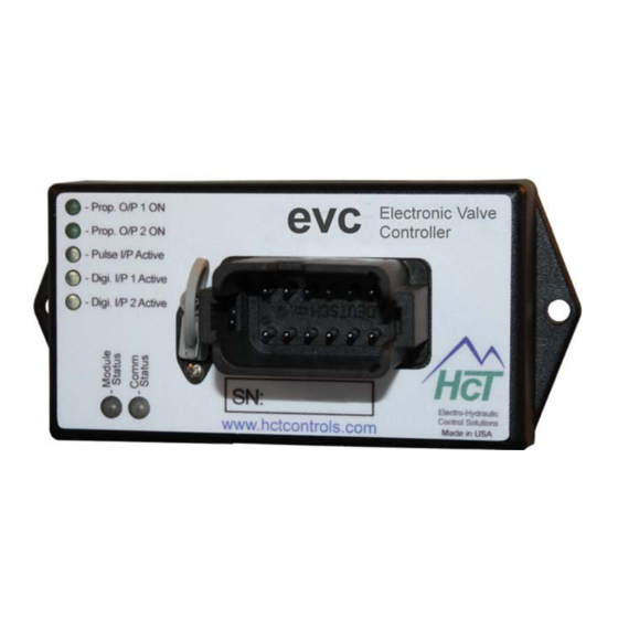
evc/epc Controller
With SAE J1939 Interface
evc/epc
Electronic Valve Controller
User Guide
High Country Tek, Inc. reserves the right to improve this product at any time and without notice. This manual
may contain mistakes and printing errors. The information in this publication is regularly checked and
corrections made in the next issue. Please check our website or contact our customer support for latest version.
HCT accepts NO liability for technical mistakes or printing errors or their consequence
1
023-00354-Rev1.4
evc/epc User Manual
Copyright © High Country Tek, Inc. – 2013
Advertisement
Table of Contents

Related Manuals for HCT evc


Summary of Contents for HCT evc
- Page 1 The information in this publication is regularly checked and corrections made in the next issue. Please check our website or contact our customer support for latest version. HCT accepts NO liability for technical mistakes or printing errors or their consequence ...
- Page 2 For our latest information, products, updates, guides and accessories, please visit us at: www.hctcontrols.com The information in this publication is intended as a guide only, and High Country Tek, Inc. (HCT) takes NO responsibility for usage and implementation in any user entered values into the provided GUI structure.
-
Page 3: Table Of Contents
Software Safety ............................... 5 Controller Specification ........................... 6 Controller Mounting Information ........................6 Controller Input vs Output ..........................7 Using the evc/epc with your PC ........................8 evc/epc GUI ..............................10 File ................................ 10 Default Settings ............................. 11 Environment ............................11 Password .............................. -
Page 4: Welcome
Introduction This manual explains the installation and use of the evc/epc Digital Controllers. Users need to understand the hazards in an electromechanical environment. Read this entire manual before installation. Pay particular attention to caution and safety information. -
Page 5: Product Application Guidelines
The GUI and controller software give the user flexibility and ease of use, even for novice users. The GUI is not intended to be connected to a non-evc/epc unit. Care must be taken to use the correct GUI and hardware combination. After program entries, cycle the power to ensure changes are accepted by the unit. -
Page 6: Controller Specification
With SAE J1939 Interface Controller Specification Housing Type HCT unique encapsulated block Power Supply Voltage 9 to 32V (Absolute Maximum) 125 mm Current Consumption Valve current + 50mA Quiescent (Max) Command Inputs SAE J1939 ‐ Prop. O/P 1 ON Electronic Valve 2x switches (ON/Off) ‐... -
Page 7: Controller Input Vs Output
= 0, I = 1A The input impedance is 100K. 0 to +10V Input: = 0, I = 1A The input impedance is 100K. NOTE: All tests conducted at 70F ambient, 24V supply with 8 coil and I set to zero and I set to 1A. max 023-00354-Rev1.4 evc/epc User Manual Copyright © High Country Tek, Inc. – 2013... -
Page 8: Using The Evc/Epc With Your Pc
System Requirements Windows XP, Vista or Windows7, 100MB or greater free disk space. Insert the CD into the PC drive and follow the on-screen instructions. This will install the evc/epc GUI, manual and help files. Install the Com Port drivers for the evc/epc. - Page 9 At start up the GUI searches the PC com ports for the evc/epc controller. The default MAC ID is 1. If the evc/epc has been programmed with a different Mac ID, you can search for the controller by “Find Module” or enter the Mac ID. The “Find Module” will restart the operation when the unit responds with its information and Mac ID.
-
Page 10: Evc/Epc Gui
Restore unit to last permanent settings saved: Reload RAM with settings stored in the EEPROM. This will undo all changes made since the last Permanent Save. Restore unit settings from data file (.dat): Load the data file from the PC to the evc/epc for different modes of operation. -
Page 11: Default Settings
In the Automotive Environment, load control is called “Anti-Stall” and in the Agriculture environment the same function is called “HP Limiting”. Password “Enter Password” unlocks certain features of the GUI. Passwords are ‘cAsE SeNsitivE’. 023-00354-Rev1.4 evc/epc User Manual Copyright © High Country Tek, Inc. – 2013... -
Page 12: Help
Manual: Will open the folder in C:\\HCT products/Digital Controllers, or browse to other locations. Exit Exits the evc/epc GUI and frees up the com port and memory used by the application. You can exit the GUI with or without saving the changes. Dashboard, Status and Graphing Windows... -
Page 13: Data Logging
Each log begins with a list of unit settings and is followed by real time operational information. The sample rate depends on the workload of the PC and the evc/epc at recording. A timestamp scales the logs appropriately. Subsequent logs may be stored in a new file or appended to the original log file by selecting the original file. - Page 14 Monitors RPM and adjusts the output accordingly. 3. Single Coil Pump Control / Valve Control Controls the single-coil pump/valve. 4. Dual Coil Pump Control / Valve Control Controls the dual-coil pump(s)/valve(s). 023-00354-Rev1.4 evc/epc User Manual Copyright © High Country Tek, Inc. – 2013...
-
Page 15: Dashboard
Supply Volts – Displays the voltage at the main Power Supply Input - (pin 1). G Average Coil Current – Applies averaging function to the displayed coil current. 023-00354-Rev1.4 evc/epc User Manual Copyright © High Country Tek, Inc. – 2013... -
Page 16: Output A Or B Coil Settings
Coil A/B Min Current (0 to 3Amps) Determines the min current or duty cycle when the demand is > 0. Fine tune it to balance machine safety and valve responsiveness. 023-00354-Rev1.4 evc/epc User Manual Copyright © High Country Tek, Inc. – 2013... - Page 17 When Current Feedback is “OFF”, the Coil A/B Min Current setting does not apply and is grayed out. The Max Current is used as a reference for the evc/epc to declare a coil short condition when the output current is 0.5A higher than the max setting.
- Page 18 100%. When Ignore Open is “OFF” and Current Feedback is “ON”, the evc/epc will declare an error when the output duty cycle reaches 100%. When Current Feedback is “OFF”, Ignore Open does not have any impact.
-
Page 19: Manual Mode
All settings on this tab are temporary and will immediately affect the outputs. In manual mode all limits and controls are bypassed. The evc/epc goes back to normal operation when exiting the GUI in manual mode. Cycling power on the unit will reset the controller and remove manual override. -
Page 20: Command & Error Settings
To use this feature, the Analog Center Active has to be “ON”. This safety feature ensures that the system will NOT immediately go to the previous settings after cycling the power. 023-00354-Rev1.4 evc/epc User Manual Copyright © High Country Tek, Inc. – 2013... - Page 21 0% output. For industrial applications, the input is ±5V or ±10V , please use a Command Signal Conditioner with the evc/epc controller. CSC-0505 – accepts ±5V and converts to 0-5V. CSC-1005 – accepts ±10V and converts to 0-5V.
- Page 22 Pot Maximum It sets the max command input. This demands 100% output. If the command input is > POT Maximum + the Command Margin, the evc/epc will declare an error and the outputs go to the default settings.
-
Page 23: Pulse Input Settings
RPM stop Set-Point or No Load RPM (1 to 65535) – The set-point where coil A current reaches 0 in Anti-Stall or HP limit modes. If auto-reverse is ON, reverse cycle will start at this rpm. 023-00354-Rev1.4 evc/epc User Manual Copyright © High Country Tek, Inc. – 2013... -
Page 24: Global Settings
“HP management with fixed command”. Recover from loss of signal When “ON”, the evc/epc automatically recovers after the pulse input and the analog input(s) are back in range. The evc/epc automatically recovers from a SAE J1939 message timeout error. -
Page 25: Factory Settings
OEM Password Users may change the OEM password. Just don’t forget it. When the GUI is purchased, the initial password is included. If lost, please contact HCT. 023-00354-Rev1.4 evc/epc User Manual Copyright © High Country Tek, Inc. – 2013... -
Page 26: Sae J1939
“ON”, the outputs will resume normal operation when the message is received. MAC ID – Displays and allows changing the MAC ID. It is the network address for this specific evc/epc. Report Analog Values – When “ON”, it does not force to change settings. -
Page 27: Operational Modes
Coil A and B outputs may be driven independently for two Single-Coil valves or for one Dual-Coil Valve. See Coil Settings, Command & Error, Global Settings sections. Dual Coil Valve or Pump Control Single Coil Valve or Pump Control Center (2.5V) Coil A max current Coil B min current Coil A min current Command Signal Input 023-00354-Rev1.4 evc/epc User Manual Copyright © High Country Tek, Inc. – 2013... -
Page 28: Anti-Stall Or Horsepower Management With Fixed Command
When the measured RPM starts to drop below the “RPM Slow”, Coil A current is reduced proportionally to the measured RPM. Coil A current becomes zero when the measured RPM reaches “RPM Stop”. (1500RPM). 023-00354-Rev1.4 evc/epc User Manual Copyright © High Country Tek, Inc. – 2013... - Page 29 If the Reverse Retry Count is depleted and the measured RPM remains below RPM Stop, the evc/epc will declare an error. At start-up the measured RPM must initially reach the “RPM Slow” to allow the evc/epc to ramp up Coil A. This ensures that the prime mover has started and is at a stable speed.
-
Page 30: Anti-Stall Or Horsepower Management With Variable Command
023-00354-Rev1.4 evc/epc User Manual Copyright © High Country Tek, Inc. – 2013... -
Page 31: Dual Output With Over Speed Protection
When the measured RPM ≥ Set-point A RPM, coil A ramps up to maximum current. When the measured RPM ≥ Set-point B RPM, coil B ramps up to maximum. 023-00354-Rev1.4 evc/epc User Manual Copyright © High Country Tek, Inc. – 2013... -
Page 32: Constant Flow Mode
Thus it maintains constant flow of the pump. When the measured RPM is 1500rpm, output A provides max current. When the measured RPM is 1800rpm, output A provides 0 current. 023-00354-Rev1.4 evc/epc User Manual Copyright © High Country Tek, Inc. – 2013... -
Page 33: Electrical Diagram
Manual Selection of Coil A or B Pin 10 Coil A Proportional output + (sourcing) Pin 11 Coil B Proportional output + (sourcing) Pin 12 0V power GND 023-00354-Rev1.4 evc/epc User Manual Copyright © High Country Tek, Inc. – 2013... -
Page 34: Led Flash / Diagnostic Codes
SAE J1939 set point message timeout RED 2 pulses --------------------------------------------- SAE J1939 engine rpm message timeout RED 3 pulses --------------------------------------------- Pot not centered at reset error ORANGE 1 pulse ---------------------------------------- State error 023-00354-Rev1.4 evc/epc User Manual Copyright © High Country Tek, Inc. – 2013... -
Page 35: Sae J1939 Can Bus
With SAE J1939 Interface SAE J1939 CAN Bus The evc/epc can be controlled by messages received over the SAE J1939 Bus. The EEC1 (PGN: 61444 SA: 0) engine RPM (SPN: 190) can be monitored for use in anti-stall and closed loop operations. -
Page 36: Status Message Format
System in Startup Mode 1 bit System in Shutdown Mode 1 bit not used 1 bit not used 2 Bytes Coil A Current (mA) 2 Bytes Coil B Current (mA) 023-00354-Rev1.4 evc/epc User Manual Copyright © High Country Tek, Inc. – 2013... -
Page 37: Analog Values Message
Operational Range 0 to 3000mA Data Length 2 Bytes Resolution 0.125 rpm/bit, 0 offset Data Range 0 to 8,031.875 rpm Operational Range 0 to 8,031.75 rpm 023-00354-Rev1.4 evc/epc User Manual Copyright © High Country Tek, Inc. – 2013... - Page 38 FF7C FFFC FF27 FFA7 FF52 FFD2 FF7D FFFD FF28 FFA8 FF53 FFD3 FF7E FFFE FF29 FFA9 FF54 FFD4 FF7F FFFF FF2A FFAA FF55 FFD5 FF2B FFAB FF56 FFD6 023-00354-Rev1.4 evc/epc User Manual Copyright © High Country Tek, Inc. – 2013...
-
Page 39: Problems Installing The Com Port Adapters
This allows device properties to be changed or devices to be uninstalled even though the device is not physically connected to the PC. Control Panel System Properties "Advanced" option and click "Environment Variables" In the System Variables sections, click "New" 023-00354-Rev1.4 evc/epc User Manual Copyright © High Country Tek, Inc. – 2013... - Page 40 When you connect PC to the unit, give the computer time to find and install the driver. Option 2 In control panel, “Add or Remove Programs” Remove old versions of FTDI software. Remove Windows Driver Package - FTDI CDM Driver Package. 023-00354-Rev1.4 evc/epc User Manual Copyright © High Country Tek, Inc. – 2013...
- Page 41 Demolition Equipment Cooling Solutions Military Apparatus Specialty Use Remote Control HCT Product Sales and Support: Power Generation Emission Controls For a full list of authorized distributors worldwide, please visit: Integrated Drivers www.hctcontrols.com/distributors/index.htm ...
Need help?
Do you have a question about the evc and is the answer not in the manual?
Questions and answers