
Related Manuals for HCT MVP-R Series


Summary of Contents for HCT MVP-R Series
- Page 1 MVP-R MVP-R Proportional Valve Ramping Controller User Manual www.enovationcontrols.com 021-MVP-R Rev C Copyright © High Country Tek by Enovation Controls - 2019...
-
Page 2: Revision Record
MVP-R Revision Record Description Date Released Last Updated by Rev A Initial Revision 16-Dec-13 Rev B Upgrade to 32V and IP65 ratings 14-Oct-14 Rev C Removed 2.5A Option 15-Feb-19 021-MVP-R Rev C Copyright © High Country Tek by Enovation Controls - 2019... -
Page 3: Table Of Contents
MVP-R Contents Revision Record ..............................2 HCT Introduction ..............................4 Product Use Limitations ............................4 Product Application Guidelines ..........................5 MVP-R Ramping Controller ............................ 6 Operating Specifications ..........................6 Physical Description ............................7 User Interface ..............................7 Configuration ..............................8 Parameter List ............................... -
Page 4: Hct Introduction
HCT products are encapsulated in solid flame resistant material for maximum durability, electrical integrity and complete environmental security. HCT is a market leader in many application arenas, including hydraulic generator, e-Fan and hydraulic fan system controls. These controllers facilitate significant fuel, emission and operational savings. -
Page 5: Product Application Guidelines
MVP-R Cautions Changing setup values or operating modes while a machine is running may cause unintended machine movement. It could lead to possible injury or death. Any moving parts should be disabled prior to changing setup values or operating modes. In every case, exercise caution and work should be completed only by qualified personnel. Product Application Guidelines ALWAYS do the following •... -
Page 6: Mvp-R Ramping Controller
The MVP-R controller drives proportional solenoid valves with adjustable ramp times. Once configured, the settings are permanently stored in the controller memory. MVP-R Features Easily configured using HCT Graphical User Interface (GUI) or HCT Hand Held Interface (HHI) LED indication of power, output current and fault status ... -
Page 7: Physical Description
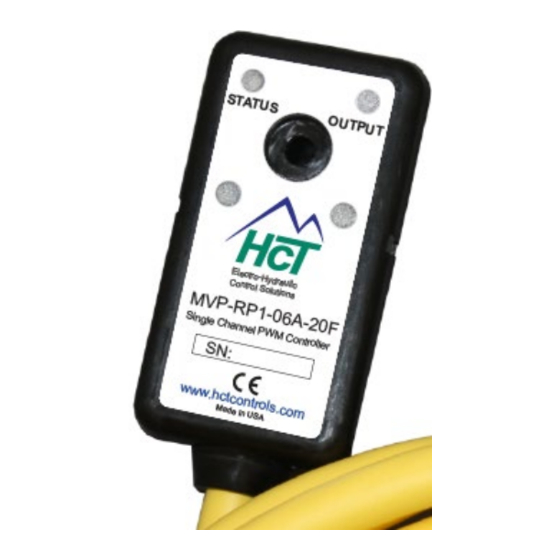
MVP-R Physical Description 60mm 30mm 19mm 43650 Form A There are two indicator LEDs: STATUS and OUTPUT. The STATUS LED is green when the applied voltage is within the operating range. The OUTPUT LED is yellow and the brightness will vary with the output current. In the case of a fault the STATUS LED will flash red with a flash code. -
Page 8: Configuration
The GUI has 4 buttons: Lock, Unlock, Up, and Down. There are short-cut keys: ‘/’(lock), ‘*’(unlock), ‘+’(up), and ‘- ‘(down). The HCT Hand Held Interface has the same 4 buttons and a 2-line LCD display. Use the up and down arrows to navigate through the parameter list. The display will show the next parameter in the list when pressed. - Page 9 MVP-R When the lock button is pressed, the changes take effect immediately. Change values only when the machine is running. “Read settings from controller” displays a static table of values from non-volatile memory. The changes made to the settings by selecting “lock” are not updated in the table unless “read settings from controller” is selected again. To save the settings into a file for future use, click “read settings from controller”...
- Page 10 MVP-R When uploading settings from a data file, the static table shows the settings from the data file, but they are not in the controller yet. Click “write settings to controller” before clicking “read settings from controller”. After this step, the static table will display the MVP settings from the data file.
-
Page 11: Parameter List
MVP-R Parameter List The following table outlines the MVP-R parameters as well as the limits and units of measure for each parameter. Parameter Limits Units MVP-RPx-xxx Version # Ramp time factor X1, /10 Mode # Ramp up time 0.0 to 120.0 Seconds Ramp down time 0.0 to 120.0... - Page 12 MVP-R MVP-RPx-xxx The title parameter is fixed. It displays the model number and the firmware version. RAMP TIME FACTOR Sets the rate of change for the output current. If the Ramp Time Factor is x1, the ramp time will match the ramp time settings. If it is set to 1/10, the ramp time will be 1/10 of the ramp time setting.
-
Page 13: Wiring
MVP-R Wiring MVP-RP2 Wiring MVP-RP1 Wiring Terminal Function Terminal Function Brown Brown Blue PWR GND Blue PWR GND Black Enable Input GRN/YEL Connector GND White Not Used Not Used GRN/YEL Connector GND Order Information M V P - R P 1 - 0 6 A - 1 0 F 10F = 10ft cable 20F &... -
Page 14: Application Examples
MVP-R Application Examples Single Solenoid Control The MVP can drive a single solenoid. Set the dither and output settings according to the valve specifications. Output Current +V Power Input 9 - 32VDC FUSE Brown PWR + Blue GND Prop. PWM (Sourcing) MVP-RP1 Seconds Electronic Valve... - Page 15 MVP-R 021-MVP-R Rev C Copyright © High Country Tek by Enovation Controls - 2019...
Need help?
Do you have a question about the MVP-R Series and is the answer not in the manual?
Questions and answers