Gazebo penguin W1207-12 Assembly Instructions Manual
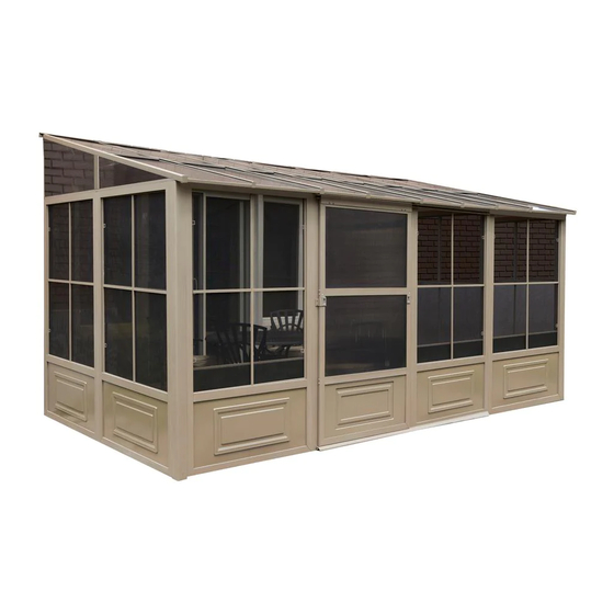
8 x 12 solarium
Hide thumbs
Also See for W1207-12:
- Assembly instructions manual (14 pages) ,
- Instruction manual (39 pages)
Advertisement
Quick Links
W1207-12 / W1207-32
8 X 12 SOLARIUM
ASSEMBLY INSTRUCTIONS
DO NOT DESTROY THE BOXES UNTIL COMPLETELY ASSEMBLED
PLEASE VERIFY THE CONTENT OF EACH BOX AGAINST THE LIST OF PARTS
Assembly by two or three adults is suggested.
Requires 96" clearance at the wall
Base Dimensions 144''x 94 1/2'', Largest Dimensions 144''x98 1/2'' (see pg.12)
W1207.1207-18.EN.doc
WEB VERSION
1
Advertisement

Related Manuals for Gazebo penguin W1207-12


Summary of Contents for Gazebo penguin W1207-12
- Page 1 W1207-12 / W1207-32 8 X 12 SOLARIUM ASSEMBLY INSTRUCTIONS DO NOT DESTROY THE BOXES UNTIL COMPLETELY ASSEMBLED PLEASE VERIFY THE CONTENT OF EACH BOX AGAINST THE LIST OF PARTS Assembly by two or three adults is suggested. Requires 96” clearance at the wall Base Dimensions 144’’x 94 1/2’’, Largest Dimensions 144’’x98 1/2’’...
-
Page 2: Tools Required
TOOLS REQUIRED: Screwdriver (Philips #2) Knife File (smooth) Needle-nosed pliers Rubber mallet Step ladder (minmum 6' in height) Spatula Power drill Tube of silicon Drill bit 5/16" cement (according to surface) BEFORE STARTING: Ensure that you have a solid base, such as concrete or wooden deck,... - Page 3 STEP #3 Assemble ML-3, N-3, O-3, and MR-3 as shown ASSEMBLE PIECES and position evenly above vertical guides, at 96’’ BEFORE SCREWING from the ground. Secure wall track and vertical THEM TO THE WALL tracks to brick or cement wall by drilling through the aluminum and using screws Xx-3.
- Page 4 STEP #5 Set right rafter T-3 over last bracket then secure it with Bb-3 screw and continue screwing through joint K-3 with the Bb-3 screw. Secure to Q-3 bracket with self-tapping screw (PQ-3). Repeat on left side with rafter S-3. STEP #6 Set U-3 rafters over the middle of each panel with Bb-3 screws at the top and...
- Page 5 STEP #7 Remove protective film from two (2) sides of each panel and make sure the top side of the panel faces the sunlight. Insert and slide on the top groove of the rafters all the way to the end. Pp-3 should go first and last with the Qq-3 panels in between.
- Page 6 STEP #9 Insert the second row of panels into the lower groove on the rafter. Slide panels until they reach the aluminum pieces between the panels and gently tap on the panel to guide it into the aluminum groove. Use a spatula if needed to make it fit.
- Page 7 STEP #11 On the inside of the solarium under each rafter there are two rows of inserts with threads. Start the upper row with a Jj-3 at either end and screw it with Ff3 and in between the Kk-3 panels. Use Ff-3 screws at the lower row Ll-3 at the 2 ends then the others in between the Mm-3 panels.
- Page 8 STEP #13 Lift up door and track inside of solarium then set it over the door opening by screwing at the top. First use bolts (Ww) and washers (Gg-3) on the inside and female bolts (Cc-3-2) on the outside for the top assembly.
-
Page 9: Special Notes
STEP #14 Anchor the solarium to the deck or floor securely using screws and shields supplied. See diagram below. SPECIAL NOTES To remove a screen, remove the two (2) screws at the top of the frame then pull sideways to the opposite end of the handles to remove. - Page 10 W1207-12 SAND PARTS LIST PACKED PACKED DESCRIPTION DRAWING DESCRIPTION DRAWING IN BOX IN BOX 10-497-12 10-496-12 FRAME NEXT REGULAR TO DOOR FRAME (Has more holes) 10-499-12 10-498-12 SLIDING DOOR SLIDING DOOR FRAME 11-544-12 11-545-12 CONNECTING TOP DOOR PIECE RAIL 11-546-12...
- Page 11 PACKED PACKED DESCRIPTION DRAWING DESCRIPTION DRAWING IN BOX IN BOX 10-510-12 10-511-12 LEFT SIDE RIGHT SIDE RAFTER RAFTER 10-512-12 10-513-12 REGULAR MIDDLE RAFTER ROOF JOINT 10-514-12 10-515-12 MIDDLE ROOF EDGING JOINT 10-516-12 08-156-12 EDGING SCREW 08-158-12 08-161-12 BOLT BOLT Bb-3 Cc-3 08-169-12 12-037-12...
- Page 12 PACKED PACKED DESCRIPTION DRAWING DESCRIPTION DRAWING IN BOX IN BOX 10-518-12 10-519-12 REGULAR ROOF TOP ROOF REINFORCE CROSSBAR Ll-3 Kk-3 10-520-12 08-134-12 ROOF TOP UPPER DOOR REINFORCE RAIL END CAP Mm-3 10-521-12 ( 51 ½” X 24 ½”) 08-135-12 SCREW LEFT+RIGHT Oo-3 ROOF PANEL...
- Page 13 W1207-32 SLATE PARTS LIST PACKED PACKED DESCRIPTION DRAWING DESCRIPTION DRAWING IN BOX IN BOX 10-497-32 10-496-32 FRAME NEXT REGULAR TO DOOR FRAME (Has more holes) 10-499-32 10-498-32 SLIDING SLIDING DOOR DOOR FRAME 11-544-32 11-545-32 CONNECTING TOP DOOR PIECE RAIL 11-546-32 08-138-32 BOTTOM DOOR PLASTIC...
- Page 14 PACKED PACKED DESCRIPTION DRAWING DESCRIPTION DRAWING IN BOX IN BOX 10-510-32 10-511-32 LEFT SIDE RIGHT SIDE RAFTER RAFTER 10-512-32 10-513-32 REGULAR MIDDLE RAFTER ROOF JOINT 10-514-32 10-515-32 MIDDLE ROOF EDGING JOINT 10-516-32 08-156-32 EDGING SCREW 08-158-32 08-161-32 BOLT BOLT Bb-3 Cc-3 08-169-32 12-037-32...
- Page 15 PACKED PACKED DESCRIPTION DRAWING DESCRIPTION DRAWING IN BOX IN BOX 10-518-32 10-519-32 REGULAR ROOF TOP ROOF REINFORCE CROSSBAR Ll-3 Kk-3 10-520-32 08-134-32 ROOF TOP UPPER DOOR REINFORCE RAIL END CAP Mm-3 10-521-32 ( 51 ½” X 24 ½”) 08-135-32 SCREW LEFT+RIGHT Oo-3 ROOF PANEL...
- Page 16 W1207.1207-18.EN.doc WEB VERSION...
-
Page 17: Maintenance Notes
Warranty set forth below, it is warranted to be free of material and manufacturing defects for a period of one year from the date of purchase. Should the product become damaged, or the warranty period has expired, please contact Gazebo Penguin Customer Service Department for a complete schedule of replacement parts and prices.
Need help?
Do you have a question about the W1207-12 and is the answer not in the manual?
Questions and answers