
Related Manuals for Wacker Neuson ST11


Summary of Contents for Wacker Neuson ST11
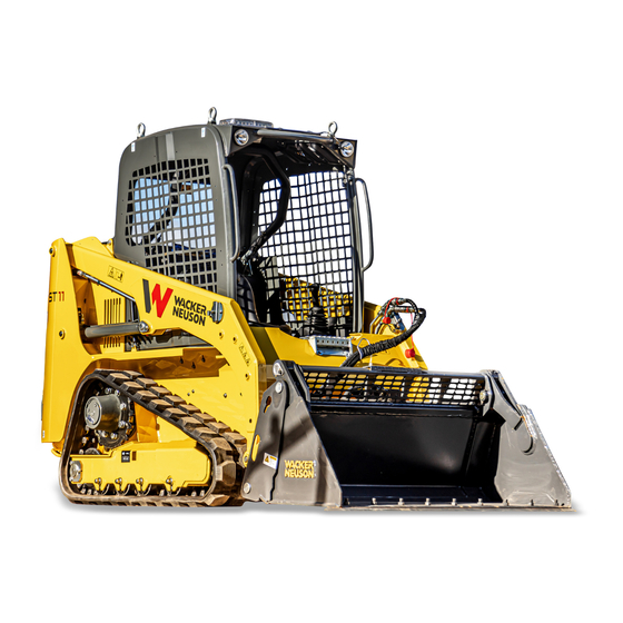
- Page 1 OPERATION & MAINTENANCE MANUAL Compact Track Loader ST11 Item 8009641121 Revision Date March 2022...
- Page 2 PRELIMINARY INFORMATION This manual is supplied together with the spare parts manual with each machine. The manual was created and formulated in conformity with the EEC regulations and in particularwith the UNI-ISO 6750 regulation. The manual supplies information about the operation of the machine, with particular reference tothe safety procedures to adopt during its use.
-
Page 3: Table Of Contents
Table of Contents PRESENTATION OF THE MACHINE GENERAL SAFETY REGULATIONS OPERATER CONTROLS EQUIPMENT AND ACCESSORIES MAINTENANCE Page 3 of 61 Item – Rev(s): 8009641121– 101... -
Page 4: Presentation Of The Machine
01 – PRESENTATION OF THE MACHINE The loading shovel has been designed and built for loading and unloading earth, gravel, sand, debris and other loose material and is however suitable to operate in compliance with the features and performance indicated in this manual. It is a machine with Diesel internal combustion motorisation with hydrostatic transmission, joy-stick type servo-controls for traversing and manoeuvre of the arms and the bucket. - Page 5 TECHNICAL DATA ENGINE Brand and model Kubota V1505T Calibration Power at 2800 rpm HP/Kw 41/30 Cylinders Nº Displacement 1498 Cooling water HYDRAULIC SYSTEM: Hydrostatic drive with double axial piston pump and variable cylinders connected to two two- speed geared motors, one for each track roller. Negative braking system on the geared motors Main variable-cylinder axial piston pump Lt/min...
- Page 6 OVERALL DIMENSIONS TRANSPORT AND HANDLING LOADING WITH RAMPS AND TRANSPORT BY TRUCK The machine loading and unloading operations must be carried out on a compact and level surface. Check that the transport vehicle is in perfect condition. Apply the hand brake and insert safety wedges at the front and rear of the rear axle tyres.
- Page 7 The ascent and descent operations must always be carried out with the machine running and the hydraulic oil at operating temperature. Do not use the ramps as a gangway for crossing from one vehicle to the next. For loading and unloading of the machine it is recommended to ascend in reverse gear and descend in forward gear.
- Page 8 If the eyebolts are removed, close the four seats with the plastic caps supplied. Any infiltration of water could seriously damage the electrical system of the right-hand and left-hand dashboard. Restrict the lifting area, prohibiting access to foreign personnel. Do not pass over persons or things and ensure that the loading area is free of any obstacles (electric and telephone cables, etc.).
- Page 9 PRESCRIPTIONS Working system commands must be blocked. Involuntary lifting of arms is prevented by the hydraulic block inserted on start-up of the machine. Disconnection and insertion is controlled by a button (ref. 4) on the right command panel. Obligation for approved yellow flashing light. This functions even when the use of a lighting device is not obligatory.
-
Page 10: General Safety Regulations
02 – GENERAL SAFETY REGULATIONS The plates applied, other than indicating the various manoeuvres for machine control and use, serve to point out the risks connected with machine operation. An operator who wears glasses mustuse them to read the plates. Keep all the plates clean and legible paying particular attention to the safety warnings indicated. - Page 11 SAFETY REGULATIONS FOR STARTING The machine must only be driven by qualified staff that are at least 18 years old. Before getting on, inspect the machine. To enter or exit the cabin it is advisable to always turn towards the vehicle. Use the steps and the handles.
- Page 12 REARWINDOW: To remove the glass pull the relative peg (ref. 1) positioned on the central part of the rubber seal and remove the insert it includes. Push the glasstowards the outside with force (ref. 2) and exit from the vehicle. The rear window safety exit is not suitable for use in environments where polar clothing is required.
- Page 13 WITH EMPTY SHOVEL IN ASCENT IN DESCENT SAFETY REGULATIONS FOR STOPPING AND PARKING Never leave the machine with the engine running. After leaving the driver’s seat, and after ascertaining that there are no persons near the machine, slowly lower and rest the equipment on the ground. Set the controls in the rest position. If possible, park the machine in an area where no other machines are operating and where there is no vehicle traffic.
- Page 14 ATTENTION In case of EMERGENCY it is possible to block arm descent by pressing the same button again (Ref. 5). This operation must be carried out exclusively to make the lifting arms safe. FIRE-EXPLOSION PREVENTION REGULATIONS Flames or sparks can cause the battery and fuel to explode and therefore set fire to the machine.
-
Page 15: Operater Controls
03 – OPERATOR CONTROLS DRIVER’S SEAT The driver’s seat must not be adjusted while the vehicle is moving. Danger of accidents! Always fasten the seatbelts. The driver’s seat is important for good health. Therefore it must be maintained integral. The driver’s seat can be adjusted longitudinally using the special lever positioned low on the right hand side. - Page 16 CONTROL AND AUXILIARY INSTRUMENTS CONTROL PANEL Fig. 1 Page 16 of 61 Item – Rev(s): 8009641121– 101...
- Page 17 FUEL LEVEL INDICATOR Switching on of the warning light signals the entry into the use of reserve fuel, which allows a residual autonomy of about 1 hour. KEY IGNITION SWITCH To start the machine proceed as follows: a. Insert the key in the ignition switch (Ref. 2 of fig.1) and turn clockwise to position “1”...
- Page 18 1. – POWER TAKE OFF INSERTION WARNING LIGHT (PTO) 2. – POWER TAKE OFF INSERTION WARNING LIGHT (PTO) 3. – GLOW PLUGSPRE-HEATING INDICATOR The warning light switches on after clockwise rotation of the key in the ignition block. The machine must always be started-up after the warning light switches off. 4.
- Page 19 10 – FLASHLIGHT DEVICE SWITCH Commands the device positioned above the cabin connected through a plug at the side of the left working light. ALWAYS SWITCHED ON DURING CIRCULATION ON ROADS 11 – WORKING LIGHT SWITCH Commands the working lights situated on the front part of the cabin. 12–...
- Page 20 MACHINE START-UP AND SHUTDOW Operator correctly positioned inside the driver’s cabin for use of the machine both in the transfer phase and for working. STARTING - For proper starting follow the instructions described above and as indicated below. - Once the engine has started, gradually move the accelerator (Ref.
- Page 21 MOVEMENT AND MARCH: MOVEMENT Traversing of the machine is controlled by the left joy-stick. The various joy-stick positions, de- pending on the manoeuvre to be carried out, are represented below. STRAIGHT LINE MOVEMENT Position A: FORWARD movement Position B: REVERSE movement (an acoustic safety device is activated) CHANGE OF DIRECTION Position F: 90°...
- Page 22 Position H: PROGRESSIVE RIGHT TURN IN FORWARD MOVEMENT PositionG: PROGRESSIVE LEFT TURN IN REVERSE MOVEMENT (an acoustic safety device is activated) Position E: 90° LEFT TURN Page 22 of 61 Item – Rev(s): 8009641121– 101...
- Page 23 PositionC: PROGRESSIVE LEFT TURN IN FORWARD MOVEMENT PositionD: PROGRESSIVE RIGHT TURN IN REVERSE MOVEMENT (an acoustic safety device is activated) CONTROL OF THE LIFTING ARM Position I: ARMS DESCENT Position L: ARMS ASCENT Page 23 of 61 Item – Rev(s): 8009641121– 101...
- Page 24 SHOVEL CONTROL Position M: SHOVEL CLOSURE PositionN: SHOVEL OPENING COMMANDS ON RIGHT AND LEFT JOY-STICK GRIP O: HORN control button S: Insert fast speed button T: Insert slow speed button P,Q: Power take off P.T.O. control button Page 24 of 61 Item –...
- Page 25 USE OF THE MACHINE FILLING AND EMPTYING OF THE SHOVEL FILLING To fill the shovel follow the warnings below: 1 - Lower the lifting arms completely. 2 - Turn the shovel until it touches the ground slightly with the point slightly inclined forwards 3- Advance slowly penetrating the stock pile and at the same time turn the shovel backwards until it is completely filled.
- Page 26 With the shovel in high position, move near to the vehicle to be loaded and turn the shovel forwards to carry out complete unloading. Ifthe shovel should not empty completely, open and close the shovel alternately to help the material to escape LEVELLINGTHE GROUND The machine is equipped with a floating valve,which renders the lifting arms “idle”.
- Page 27 Proceed in reverse gear and the bucket will follow the profile of the ground spreading the previously accumulated material. DIGGING AND FILLING IN DIGGING The machine is not an excavator therefore digging is only allowed on loose ground, without stones and masses and which is generally easyto penetrate with the shovel.
- Page 28 LIMITS FOR QUICKCOUPLING UTILISATIONANDRELATED EQUIPMENT, BUCKET INCLUDED. With the lifting arms in maximum collection position, and in contact with the frame, it is strictly prohibited to rotate the bucket completely towards the ground as the pivot of the quick coupling of the bucket and the bucket itself, when the rotation of the track rollers is tampered with, can cause damage to same.
-
Page 29: Equipment And Accessories
04 – EQUIPMENT AND ACCESSORIES SHOVEL REPLACEMENT OR REPLACEMENT OF OTHERACCESSORIES PREPARED FOR QUICK FITTING SHOVEL ASSEMBLY – Go to the shovel lying on the roundas shown in the diagram, turn the quick fit device forward and turn the attachment lever to the outside. - Page 30 HYDRAULIC POWER TAKEOFF (PTO) The quick couplings are positioned in the internal part of the left lifting arm and have the following features: Plane face quick couplings: 3/8” Work pressure: 180 bar Pump capacity: 39 l/min. RANGER OF SCALDING Pay particular care during the quick engagement connection and release operations as the high oil temperature could heat the points excessively and therefore render grip difficult.
- Page 31 HEATING PLANT Use the switch to control the two-speed fan in machines equipped with the heating system (ref. 13). While for functioning of the plant open tap “R” positioned above the diesel engine, corresponding to thealternator. POSITIONA: CLOSED POSITIONB: OPEN POSITION A POSITION B The cabin and driver’s position are adequatefor use in...
- Page 32 USE OF LIFTING FORKS The forks must always and only be used with the self-levelling valve installed. It is prohibited to exceed the indicated nominal capacity. Non-compliance of capacities consented by the Manufacturer causes the loss of stability of the machine or even overturning.
- Page 33 Do not operate if there is not sufficient visibility or the minimum safety requirements for the work to be carried out are not present. Never leave the machine with the engine running and the load raised from the ground. Control wear and pressure of the tracks as any failure could unbalance the load with its loss or worse, overturn the machine.
-
Page 34: Maintenance
05 – MAINTENANCE PRELIMINARY INFORMATION The maintenance operations must be done exclusively by a qualified personnel. To facilitate the control, the machine is equipped with an hour counter placed on the dashboard, which registers the functioning time and work. Only with perfect maintenance can the machine be maintained in perfect condition allowing to work well and in safety. - Page 35 LUBRICATION AND GREASING MAINTENANCESAFETY When for maintenance requirements or other, it is necessary to raise the cabin, it must always be blocked using the special supplied base level moving it from Position1 to Position 2. Analogue safety system (ref. 3), fixed inside of the engine hood, which must be installed every time the shovel lifting arms are raised to prevent uncontrolled descent.
- Page 36 The engine hood is supplied with a lever “A” that allows shutdown and blocking in a completely open position. For closure, turn lever “A”. DANGEROF SHEARING Never place any part of the body between the fixed part and the open hood as sudden closure could cause serious injury or mutilation.
- Page 37 GREASE POINTS In the scheme beside are indicated the principal greasing points: they must be supplied every 8 hours except for those with a different indication. Note: the track supporting rollers are of the permanently lubricated type, thereforethey do not need to be periodically greased. Page 37 of 61 Item –...
- Page 38 STOPPING AND RESTARTING AFTER INACTIVITY MACHINE STOPPING DUE TO INACTIVITY When anticipating a long period of machine inactivity, it is recommended to place it under cover in a dry place. Below follows some advice and precautions to take before shutting down the machine. Thoroughly clean and wash the machine with pressurised water and dry it, especially in the zones not protected by paint or without special protections.
- Page 39 SPECIAL CONDITIONS OF USE Muddy, humid, snowy terrain: Check hermetic seal of the caps and valves. Clean and check the machine overall, tightness of the nuts and screws,and check for any sagging due to knocks or formation of cracks, etc. Marine terrain: Check hermetic seal of the caps and valves.
- Page 40 REFILLING, INSPECTIONS AND CHECKS A - Pressurised filling cap (0.7 bar) to restore the level of engine cooling liquid. B - Engine cooling liquid level indicator. C - Radiator filling cap (supply complete). D - Hydraulic oil introduction cap. (38 spanner). E - Fuel introduction cap FUEL SUPPLY SYSTEM The fuel tanks are situated on the rear left and right sides of the machine;...
- Page 41 SUPPLYING, VERIFICATIONS, DIESEL MOTOR COOLING SYSTEM CONTROLS: The radiator is situated in the rear part of the machine, above the diesel engine. For capacity and filling refer to the RE-FUELLING TABLES A special warning light (Fig.1 - ref. 7), on the left dashboard, signals the inefficiency of the diesel engine cooling circuit.
- Page 42 DIESEL ENGINE LUBRICATION SYSTEM Concerning use, refilling, engine oil and coolant check, starting and stopping, air filter inspection and cleaning, and everything to do with maintenance, follow the instructions in the USE AND MAINTENANCE manual of the engine manufacturer, supplied with the machine. The instructions in this manual were taken from the use and maintenance manual of the engine manufacturer and used to simplify the topics discussed, in order to give a more complete and immediate view.
- Page 43 7. Re-attach cover “B” to the filter body “E” using handles “C”. ATTENTION It is however recommended to replace the cartridge every 6/8 months, according to the work environment. DRIVE TRANSMISSION Every tracks is activated by a hydrostatic motor-reducer. For oil checks, filling, replacement in the wheel reducers refer to that specified below. Periodically check (see MAINTENANCE TABLE) that there are no leaks and that with the machine at a standstill and the reducers positioned as indicated below, the oil reaches the envisioned level;...
- Page 44 Level checks and restoration, filling and emptying must be carried out with the machine level and horizontal and the engine at a standstill. Insert a container under the unload tap which is big enough to collect the oil. The entire operation can be made easier by dismounting the tyre after having fixed the machine opportunely.
- Page 45 TRACK TENSION CONTROLS AND ADJUSTMENT On the external sides of the track support, an opening is placed inside which a valve, greased, is positioned to adjust the tension of the track. The exact tension of both tracks is essential for the good functioning of the machine, both in driving and working phases.
- Page 46 In the event that one or both tracks need further adjustment after the machine has been restarted, repeat the operations described previously, starting from machine lifting and taking the required precautions. Re-insert the head on the valve and begin to pump oil within the device until correct track roller tension is achieved.
- Page 47 The abrasions, tears, cuts on the external surface of the track (that in contact with the ground) are in most cases due to contact with sharp stones or cutting materials (plating, glass, nails, tile chips) which cause cuts and complete or partial shredding of parts of the track.
- Page 48 HYDRAULIC SYSTEM The oil tank is situated in the rear central part of the machine, with the filling cap “D” positioned in the rear left side and accessible with the cabin raised. The visual level indicator “A” is situated on the tank’s left lateral wall. This is used to control the level of liquid container.
- Page 49 HYDRAULIC SYSTEM PRESSIONS CALIBRATION Every skid steer loader or part of it is scrupulously controlled and inspected so as to supply the client with a perfectly efficient and functional plant from a mechanical, electrical and hydraulic pointof view. To make the inspection of the hydraulic system as easy as possible, the machine is equipped with M16 x 2 quick-coupling fittings on which the pressure calibration values of the single mechanisms may be checked.
- Page 50 MECHANISMS PRESSURE TRAVERSING: (for every detection point 1; 2; 3; 4) 300 bar SERVICES: detection point 5 (arms and bucket) 180 bar SERVO-CONTROLS: detection point 6 (joy-stick) 24 bar Do not arbitrary modify the valves calibration values, because they could be the reason of malfunctionings or damages, which could compromise the machine safety.
- Page 51 ELECTRICAL SYSTEM BATTERY The machine is equipped with a battery housed in the compartment under the seat. It is visible when the cabin is raised and has the following features: VOLTAGE 12 V ABSORPTION 80 Ah If it will be necessary a battery substitution, thenew battery will have the same characteristics of the ones indicated.
- Page 52 In case of stops for a long period at low temperatures, it is recommended to protect the battery or store it in a hot and sheltered place. REMOVE THE PROTECTION BEFORE START-UP; DANGEROF FIRE. The machine is fitted with a switch located in the engine compartment, which allows disconnecting the battery for any EMERGENCY, and in case of extended stops (more than 4 hours).
- Page 53 POSITIONING OF LIGHTS 1 - DIPPED-BEAMHEADLIGHTS base H4 BULB: 12 V 60/55 W 2 - ANTEROLATERAL DIRECTION INDICATORS BULB: 12 V 21 W base BA 15S 3 - WORKINGLIGHTS BULB: 12 V 50 W base GE 886 4 - FLASHINGLIGHT base H1 BULB: 12 V...
- Page 54 SUPPLY TABLE PART Qty. FUEL: BRAND and TYPE FUEL TANK DIESELFUEL 42 lt HYDROSTATIC AND 30 lt HYDRAULIC SYSTEM AGIPARNICA46 TRAVERSINGMOTOR AGIP ROTRA MP 80W90 0,7 lt cad. REDUCERS DIESEL AGIP SIGMA S SAE 30 6,0 Kg ENGINE AGIPANTIFREEZE ENGINERADIATOR 9,0 lt COOLINGLIQUID ARTICULATIONS, PINSAND...
- Page 55 MAINTENANCE TABLE OPERATIONTO COMPONENT FREQUENCYINHOURS 1000 PERFORM CONCERNED • AIR FILTER - CARTRIDGE • RADIATOR - FINNING • SILENCER AND SHOVEL CLEANING • GAS OIL FILTER CUP • DIESEL FUEL TANK • HYDRAULIC OIL TANK MOTOR CUP OIL LEVEL • COOLANT LEVEL •...
- Page 56 FAULTS: CAUSES AND REMEDIES ENGINE FAULT CAUSE REMEDY BATTERY DISCONNECTED CONNECT BATTERY FLAT RECHARGE, REPLACE BATTERY TERMINALS OXIDISED, CLEAN, CONNECT, TIGHTEN DISCONNECTED OR LOOSE GLOW PLUG FUSE TRIPPED REPLACE FUSE STARTING MOTOR INEFFICIENT INSPECT AND REPLACE IF NECESSARY INJECTION PUMP, DIRTY, FAULTY CLEAN OR REPLACE THE FAULTY INJECTORS COMPONENT...
- Page 57 BREAKAGE OF ENGINE COOLING FAN INSPECT, REPLACE CONTROL PUMP BREAKAGE OF ENGINE COOLING FAN ENGINE OIL LEVEL TOO LOW CHECK AND TOP UP PRESSURE LOW PIPE AND CONNECTOR OIL LEAKS CHECK, REPLACE OR TIGHTEN ENGINE OIL ENGINE OIL FILTER BLOCKED REPLACE OIL LEAK CHECK, LOOK FOR THE CAUSES, FILL UP...
- Page 58 HYDRAULIC SYSTEM FAULT CAUSE REMEDY UNSUITABLE HYDRAULIC OIL USE RECOMMENDED OIL HYDRAULIC PIPES BLOCKED CALL AN AUTHORISED WORKSHOP HYDRAULIC FILTER CLOGGED REPLACE HYDRAULIC PUMPS DAMAGED CHECK, CALL AN AUTHORISED WORKSHOP MAX. PRESSURE VALVES FAULTY, NOT CHECK, CALIBRATE AND REPLACE IF CALIBRATED NEEDED HYDRAULIC OIL LEVEL LOW...
- Page 59 HYDRAULIC PUMP DAMAGED INSPECT AND REPLACE IF NECESSARY (CALL AN AUTHORISED WORKSHOP) HYDRAULIC OIL LEVEL LOW CHECK AND RESTORE IF NECESSARY POOR EFFICIENCY SERVOCONTROLS HYDRAULIC SUCTION FILTER BLOCKED INSPECT AND REPLACE IF NECESSARY PIPES, CONNECTORS FAULTY OR LOSE INSPECT AND REPLACE OR TIGHTEN IF NECESSARY CURSOR DAMAGED INSPECT, REPLACE...
- Page 60 MAINTENANCE NOTES HOURS DATE WORK DONE PARTS CONCERNED WORKED Page 60 of 61 Item – Rev(s): 8009641121– 101...
- Page 61 MAINTENANCE NOTES HOURS DATE WORK DONE PARTS CONCERNED WORKED Page 61 of 61 Item – Rev(s): 8009641121– 101...
Need help?
Do you have a question about the ST11 and is the answer not in the manual?
Questions and answers