Table of Contents
Advertisement
Quick Links
Advertisement
Table of Contents

Related Manuals for Digium TE400 Series


Summary of Contents for Digium TE400 Series
- Page 1 TE400 Series TE420B/TE420/412P/410P/407P/405P User Manual 601-00009 Rev. B...
- Page 2 Digium, Inc. Digium, Inc. has made every effort to ensure that the instructions contained in this document are adequate and error free. The manufacturer will, if necessary, explain issues which may not be covered by this documentation.
- Page 3 Note: Shielded T1/E1/J1 cables are required for compliance purposes. 47 CFR Part 15, Subpart B / 47 CFR Part 15, Subpart B, Class B EN 55022:1998 Class B / EN 55022:1998 Class B Radiated and Conducted EN 55024:1998 / IEC 61000 Digium, Inc. Page 3...
- Page 4 Federal Communications Commission Part 68 This equipment complies with Part 68 of the FCC rules and the requirements adopted by the ACTA. On the back of the TE400 Series printed circuit board is a label that contains, among other information, a product identifier in the format US:AAAEQ##TXXXX.
- Page 5 Industry Canada Compliance Information Notice: The Industry Canada label applied to the product (identified by the Industry Canada logo or the "IC:" in front of the certification/ registration number) indicates that the Industry Canada technical specifications were met. Digium, Inc. Page 5...
-
Page 6: Table 1: Te400 Series Cards
Introduction to TE400 Series Documentation This manual is a user guide for Digium’s TE400 Series cards. The Digium TE400 Series cards are a T1/E1 capable card series created for voice and data. The cards in this series are as follows:... - Page 7 Document Organization The TE400 Series user’s guide is organized in the following manner: Chapter/ Title Description Appendix Overview Identifies the features of the card you received. This chapter covers applications and uses of the TE400 Series cards in the real world.
- Page 8 (ESD) wrist strap while handling the device. The Electrical Hazard Symbol indicates a possibility of electrical shock when operating this unit in certain situations. To reduce the risk of damage or injury, follow all steps or procedures as instructed. Digium, Inc. Page 8...
- Page 9 To reduce the risk of damaging the unit or your equipment, do not attempt to open the enclosure or gain access to areas where you are not instructed to do so. Refer servicing to qualified service personnel. Save these instructions for future reference. Digium, Inc. Page 9...
-
Page 10: Table Of Contents
Installing Asterisk ........38 Chapter 3 Digium, Inc. Page 10... - Page 11 Glossary and Acronyms ........66 Digium, Inc.
- Page 12 Insert the Card ......32 Figure 11: Example dmesg Output ..... . 55 Digium, Inc. Page 12...
- Page 13 List of Tables Table 1: TE400 Series Cards ..... . . 6 Table 1: Card Identifiers ......36 Table A-1: RJ45 Telco Port Connector .
-
Page 14: Overview
Signaling), CCS (Common Channel Signaling), E&M, Primary Rate ISDN (PRI), and several data modes (PPP, HDLC, Cisco HDLC, and frame relay). The TE400 Series cards are capable of running in E1, T1, or J1 modes. They are also capable of DACSing channels from one span to another. - Page 15 – – EuroISDN – 4ESS (AT&T) – 5ESS (Lucent) – DMS100 – – Q.SIG E&M Wink – Feature Group B – – Feature Group D FXO and FXS Ground Start – – Loop Start Digium, Inc. Page 15...
- Page 16 Loop Start with Disconnect Detect – The TE400 Series cards can be used to connect your Asterisk machine to the PSTN world, your channel bank, or even another PBX. This is accomplished via a T1/E1 interface. The cards allow Asterisk software to connect to your network, creating a professional telephony environment.
-
Page 17: Figure 1: Sample Legacy Phone Application
Chapter 1: Overview CLEC Asterisk Server Legacy Legacy Phones Legacy Channel Bank Analog Phones Figure 1: Sample Legacy Phone Application Digium, Inc. Page 17... -
Page 18: Figure 2: Sample Channel Bank Application
Chapter 1: Overview CLEC Asterisk Channel Bank Server Channel Bank Channel Bank Analog Phones Figure 2: Sample Channel Bank Application Digium, Inc. Page 18... -
Page 19: Figure 3: Sample Ip Phone Application
Chapter 1: Overview Switch ASTERISK SERVER CLEC Phones Figure 3: Sample IP Phone Application Digium, Inc. Page 19... -
Page 20: Echo-Cancellation
Chapter 1: Overview Echo-Cancellation Users connecting their TE400 Series cards to the PSTN or other devices are likely to be placing calls that will result, at some point, in an unbalanced 4-wire/2-wire hybrid. The result of this hybrid is the reflection of a near-end echo to the calling party. -
Page 21: What Is Asterisk
It can also be built out as the heart of a media gateway, bridging the legacy PSTN to the expanding world of IP telephony. Asterisk’s modular architecture allows it to convert between a wide range of communications protocols and media codecs. Digium, Inc. Page 21... -
Page 22: Asterisk In The Call Center
Asterisk have helped reduce costs and enabled flexibility. Asterisk Everywhere Asterisk has become the basis for thousands of communications solutions. If you need to communicate, Asterisk is your answer. For more information on Asterisk visit http://www.asterisk.org http:// www.digium.com. Digium, Inc. Page 22... -
Page 23: Card Installation
Hardware Installation on page 32 Software Installation on page 33 Note: The TE400 Series card installation instructions are written so that they will apply to any card in the series. Examples and card specific information are included as needed. Digium, Inc. -
Page 24: Unpacking The Card
B or connected to a socket-outlet that has been checked to ensure that it is reliably earthed in accordance with the National Electrical Code. Shipment Inspection The following items are included in shipment of the TE400 Series: TE400 Series card (TE405P/407P/410P/412P/420/420B) Digium, Inc. -
Page 25: Identifying Communication Ports
Chapter 2: Card Installation Identifying Communication Ports The TE400 Series cards consists of four RJ45 ports and four status LEDs. The ports are used for connecting T1, E1, or J1 cables. Refer to Figure 4 on page 25 or Figure 5 on page 26 to locate the ports and LEDs. -
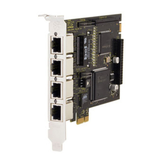
Page 26: Figure 5: Te420 Card
Chapter 2: Card Installation Timing Port Ports Status LEDs Jumpers Ident Wheel PCI Express Connector Figure 5: TE420 Card Digium, Inc. Page 26... -
Page 27: T1/E1 Selection
E1 mode. Figure 6: T1/E1 Jumpers Identifying Multiple Cards If multiple TE400 Series cards are installed in the same machine, then the wheel can be used to control the order the cards are recognized. The Ident... -
Page 28: Connecting Timing Cables
Figure 7: Ident Wheel Connecting Timing Cables The timing port allows up to four TE400 Series cards to share the same sync (timing) source from the T1 line provider, or provide a consistent sync source across multiple cards. This is a useful feature for data and fax modes and some voice applications to prevent corruption due to timing slips on the second, third or fourth TE400 Series cards. -
Page 29: Figure 8: Timing Ports Example
Chapter 2: Card Installation Figure 8: Timing Ports Example Caution. Only qualified service personnel should continue with hardware installation and configuration of the TE400 Series card. Non-qualified personnel should not attempt to perform these functions themselves. Digium, Inc. Page 29... -
Page 30: Slot Compatibility
Figure 9 on page 30. Slot Number: 0: AGP Pro Slot 1: 64-bit 5.0 volt PCI Slot 2: 64-bit 3.3 volt PCI Slot 3: 32-bit 5.0 volt PCI Slot 4: PCI Express X1 Slot Slots Figure 9: Motherboard Slots Digium, Inc. Page 30... - Page 31 PCI Express compliant slot, including lane lengths X4, X8, and X16. This means that in the motherboard shown in Figure 9, the TE420/TE420B will only fit into Slot 4. The TE420/TE420B can not be used in Slots 1 through 3. Digium, Inc. Page 31...
-
Page 32: Hardware Installation
Express slot. See Figure 10 for an example of card installation. Figure 10: Insert the Card Replace the cover to your computer. Plug all T1 or E1 equipment cables into the RJ45 ports as needed. Note: It is recommended that you use shielded cables. Digium, Inc. Page 32... -
Page 33: Software Installation
For the latest information on setting up and configuring DAHDI drivers for your Digium hardware product, please refer to the latest release of this manual which is available from the product-specific documentation section at: http://www.digium.com Digium, Inc. - Page 34 It is recommended that you use the most recent version of the Asterisk, DAHDI, and libpri software for the best results. If you have previously installed any of these, Digium recommends that you upgrade to the latest “-current” version of each.
- Page 35 PCI bus: # lspci -n Confirm that the output from lspci lists a device with Digium’s PCI vendor ID which is “d161”. The screen output should be similar to the following: 0000:01:0e.0 ISDN controller: Unknown device d161:<card identifier>...
-
Page 36: Card Identifiers
0405 TE405P 0405 A Digium TE400 Series (TE420B/TE420/412P/410P/407P/405P) card identifier should be listed. If a matching card identifier is not listed, then your machine is not PCI 2.2 (or higher) or PCI Express compatible, and the card will not work with your motherboard. - Page 37 # make install Download the latest DAHDI drivers with tools. DAHDI is available for download from: http://downloads.digium.com/pub/telephony/dahdi-linux-complete # wget http://downloads.digium.com/pub/telephony/ dahdi-linux-complete/dahdi-linux-complete- current.tar.gz Expand the downloaded file, compile its contents, and install the drivers and tools. Substitute the version of DAHDI for the X.X.X in the command lines below.
-
Page 38: Installing Asterisk
1.6.0.1 (or later). Substitute the version of Asterisk for the X.X in the command below. Asterisk is available for download from: http://downloads.digium.com/pub/telephony/asterisk # wget http://downloads.digium.com/pub/telephony/ asterisk/asterisk-X.X-current.tar.gz Expand the downloaded file, compile its contents, and install the application. Substitute the version of Asterisk for the the X.X and X.X.X in the command lines below. - Page 39 If your installation has failed, it may be because you are missing one or more of the build dependencies, the kernel headers, or the development tools. Please contact your reseller where the card was purchased, or call Digium Technical Support (+1.256.428.6161) for assistance. Complete instructions for installing Asterisk are available at www.asterisk.org.
-
Page 40: Configuration
Chapter 3 Configuration The TE400 Series cards have a variety of configuration options. This chapter provides configurations for PRI, channel bank, E&M wink, and finally, data mode. These sample configurations are provided to assist you in familiarizing yourself with the flexibility of editing the configuration files to meet your specific needs. -
Page 41: Configuring Card Features
By default, and when setting to "yes," echo cancellation is enabled and set to 16 ms (128 taps). Echo cancellation is explicitly disabled by setting: echocancel = no Digium does not recommend that users set echo cancellation to "no." Users of open source Asterisk-based echo cancelers also have the following options: echocancel = 128 (this sets 128 taps or 16ms) Digium, Inc. - Page 42 If audio quality is affected, reduce the taps length or combine your TE400 Series card with Digium's VPMOCT128. Users of Digium's VPMOCT128 hardware echo cancellation module will have 128ms of echo cancellation performed at all times unless explicitly disabled by setting the echocancel variable equal to "no."...
- Page 43 = fxo_ks group = 1 context = phones channel => 1-24 E1 channel bank signalling = fxo_ks group = 1 context = phones channel => 1-15,17-31 Note: More detailed troubleshooting information is provided on http:// www.asterisk.org. Digium, Inc. Page 43...
-
Page 44: Configuring T1/E1 Lines
=> <Number>,<Timing>,<Line Build Out>,<Framing>,<Coding>[,Yellow] Number: This is the port the T1/E1 line is plugged into. Port 1 being the furthest span from the PCI bus. The port numbers are noted on the PCI bracket. Digium, Inc. Page 44... - Page 45 2: 266-399 feet (DSX-1) 3: 399-533 feet (DSX-1) 4: 533-655 feet (DSX-1) 5: -7.5db (CSU) 6: -15db (CSU) 7: -22.5db (CSU) Framing: T1 utilizes framing set for D4 (SF) or ESF. E1 utilizes CAS or CCS. Digium, Inc. Page 45...
- Page 46 The echo cancellers are compiled and installed as part of the dahdi- linux package. You can specify the echo canceller to be used for each channel. The default behavior is for there to be no echo canceller on Digium, Inc. Page 46...
- Page 47 = <echocanceller name>,<channel(s)> A list of valid echo cancellers are specified in the sample system.conf file. The following is a typical setup for a T1 PRI in the US using software- based echo cancellation: echocanceller = mg2,1-23 Digium, Inc. Page 47...
- Page 48 1-24. fxo_ks /etc/dahdi/system.conf: loadzone = us defaultzone = us span = 1,0,0,esf,b8zs fxoks = 1-24 echocanceller = mg2,1-24 /etc/asterisk/chan_dahdi.conf: group = 1 echocancel = yes context = channelbank signalling = fxo_ks channel = 1-24 Digium, Inc. Page 48...
- Page 49 DID, but there are many other E&M options; E&M_W, E&M, Feat_B, etc. /etc/dahdi/system.conf: loadzone = us defaultzone = us span = 1,1,0,esf,b8zs e&m = 1-24 echocanceller = mg2,1-24 /etc/asterisk/chan_dahdi.conf: group = 1 echocancel = yes context = incoming signalling = feat_d channel = 1-24 Digium, Inc. Page 49...
- Page 50 = us defaultzone = us span = 1,1,0,esf,b8zs bchan = 1-23 dchan = 24 echocanceller = mg2,1-23 /etc/asterisk/chan_dahdi.conf: group = 1 echocancel = yes signalling = pri_cpe switchtype = national context = incoming channel = 1-23 Digium, Inc. Page 50...
- Page 51 = es defaultzone = es span = 1,1,0,ccs,hdb bchan = 1-15,17-31 dchan = 16 echocanceller = mg2,1-15,17-31 /etc/asterisk/chan_dahdi.conf: group = 1 echocancel = yes signalling = pri_cpe switchtype = euroisdn context = incoming channel = 1-15,17-31 Digium, Inc. Page 51...
- Page 52 [*] Wan interfaces support ---> <M> Generic HDLC support <M> Cisco HDLC support Note: Digium recommends using Linux kernel version 2.6.8 or later. The HDLC implementation in Linux kernel versions prior to 2.6.8 may not be reliable or function at all.
- Page 53 # make sethdlc # make install Load and configure the driver: # modprobe wct4xxp # dahdi_cfg to bring up the interface: sethdlc # sethdlc hdlc0 cisco Assign the interface an address: # ifconfig hdlc0 192.168.0.1 netmask 255.255.255.0 Digium, Inc. Page 53...
-
Page 54: Testing Your Configuration
(i.e., eth0) in Linux. Testing Your Configuration Load DAHDI drivers into the kernel using the modprobe utility. The appropriate driver for the TE400 Series cards is . Users in all wct4xxp countries except Australia should use the following modprobe command:... -
Page 55: Figure 11: Example Dmesg Output
Figure 11: Example dmesg Output Note: Output as shown above may vary depending on the TE400 Series card you use. from the command line and see if the span turns dahdi_tool green for each span you have connected. # dahdi_tool Digium, Inc. Page 55... - Page 56 Chapter 3: Configuration Execute the following Asterisk command to see if the span came up successfully. # asterisk # asterisk -vvvr Digium, Inc. Page 56...
-
Page 57: Chapter 4 Troubleshooting
This chapter provides frequently asked questions as identified from Digium Technical Support and possible resolutions. Multiple resources are available to obtain more information about Asterisk and Digium products. These resources are listed on page 62. What do the Status LED colors indicate? Green - Card is in-sync with the far end. - Page 58 D channel? Enter the following command: *CLI> PRI debug span X where X is the port from which you are connected. This command will show you the PRI messages coming across your D channel for that span. Digium, Inc. Page 58...
- Page 59 Stop Asterisk and edit by removing the lines defined for system.conf your card and replacing them with the following: span => 1,0,0,esf,b8zs clear = 1-24 Or if you have an E1 span: span => 1,0,0,ccs,hdb3 clear = 1-31 Digium, Inc. Page 59...
- Page 60 The second argument is the duration in seconds to run the test. This runs a pattern looptest for 60 seconds. If you receive any failures, it is possible you have a bad card and will need to call Digium Technical Support (+1.256.428.6161) How can I enable more features?
- Page 61 Use this command to set the drives into UDMA2 mode: hdparm -d 1 -X udma2 -c 3 /dev/[IDE Device] If you are still having problems, contact your reseller from which the card was purchased, or Digium Technical Support (+1.256.428.6161). Digium, Inc. Page 61...
- Page 62 Asterisk experts. Pricing on Subscription Services may be obtained from your nearest reseller or you may call Digium Sales for referral to your nearest reseller at +1.256.428.6000 or e-mail sales@digium.com.
-
Page 63: Appendix A Pin Assignments
Appendix A Pin Assignments All four ports on the TE400 Series card bracket are 8-pin RJ45 ports. The pin assignments are identified in Table A-1. Table A-1: RJ45 Telco Port Connector Description Not used Pin 1 Pin 8 Not used... -
Page 64: Specifications
Appendix B Specifications This appendix provides specifications, required environmental conditions, and maximum power consumption for the TE400 Series cards. Physical (All Cards). Size: 5” × 3.75” × 0.63” (12.7 x 9.53 x 1.6 cm) PCB size, does not include the PCI bracket Weight: 3.5 oz (100gm) - Without Echo Cancellation Module... -
Page 65: Table B-2: Maximum Power Consumption
Table B-2: Maximum Power Consumption Model Power TE420B 3.3V 5 Watts TE420 3.3V 2.5 Watts TE412 3.3V 3.0 Watts 0.5 Watts TE410 3.3V 2.0 Watts 0 Watts TE407 3.3V 3.0 Watts 0.5 Watts TE405 3.3V 2.0 Watts 0 Watts Digium, Inc. Page 65... -
Page 66: Appendix C Glossary And Acronyms
The smallest element of information in a digital system. A bit can be either a zero or a one. bits per second A measurement of transmission speed across a data connection. Digium, Inc. Page 66... - Page 67 100 MHz but adheres to stricter quality specifications. CLEC competitive local exchange carrier A term for telephone companies established after the Telecommunications Act of 1996 deregulated the LECs. CLECs compete with ILECs to offer local service. See also LEC and ILEC. Digium, Inc. Page 67...
- Page 68 Digium Asterisk Hardware Device Interface A telephony project dedicated to implementing a reasonable and affordable computer telephony platform into the world marketplace. Also, the collective name for the Digium-provided drivers for Digium telephony interface products. Digital Signal, Level 0 A voice grade channel of 64 Kbps. The worldwide standard speed for digitizing voice conversation using PCM (Pulse Code Modulation).
- Page 69 Electromagnetic Interference Unwanted electrical noise present on a power line full duplex Data transmission in two directions simultaneously. Foreign Exchange Office Receives the ringing voltage from an FXS device. Foreign Exchange Station Initiates and sends ringing voltage. Digium, Inc. Page 69...
- Page 70 (ITU-T) for multimedia communications over packet-based networks. Inter-Asterisk eXchange The native VoIP protocol used by Asterisk. It is an IETF standard used to enable VoIP connections between Asterisk servers, and between servers and clients that also use the IAX protocol. Digium, Inc. Page 70...
- Page 71 Asterisk is supported exclusively on Linux. loopback A state in which the transmit signal is reversed back as the receive signal, typically by a far end network element. Digium, Inc. Page 71...
- Page 72 A POP is usually a network node serving as the equivalent of a CO to a network service provider or an interexchange carrier. POTS plain old telephone service Standard phone service over the public switched telephone network (PSTN). This service provides analog bandwidth of less than 4 kHz. Digium, Inc. Page 72...
- Page 73 Voice over IP, gradually replacing H.323. A dedicated digital carrier facility which transmits up to 24 voice channels (DS0s) and transmits data at 1.544 Mbps. Commonly used to carry traffic to and from private business networks and ISPs. Digium, Inc. Page 73...
- Page 74 The wires are wrapped loosely around each other to minimize radio frequency interference or interference from other pairs in the same bundle. volts VoIP Voice over IP Technology used for transmitting voice traffic over a data network using the Internet Protocol. Digium, Inc. Page 74...
Need help?
Do you have a question about the TE400 Series and is the answer not in the manual?
Questions and answers