Table of Contents
Advertisement
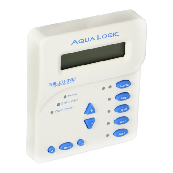
Aqua Logic
Aqua Logic
Aqua Logic
Aqua Logic
Aqua Logic
G
LDLINE
CONTROLS INC.
Automation and Chlorination
(actuators & remote display not included on some models - order separately)
Operation Manual
AQ-LOGIC-P-4
AQ-LOGIC-PS-4
for models
(all datecodes)
(0401 & earlier)
www.goldlinecontrols.com
888-921-7665
Advertisement
Table of Contents

Related Manuals for Goldline Aqua Logic AQ-LOGIC-P-4


Summary of Contents for Goldline Aqua Logic AQ-LOGIC-P-4
- Page 1 Aqua Logic Aqua Logic Aqua Logic Aqua Logic Aqua Logic Automation and Chlorination (actuators & remote display not included on some models - order separately) Operation Manual for models AQ-LOGIC-P-4 (all datecodes) AQ-LOGIC-PS-4 (0401 & earlier) LDLINE www.goldlinecontrols.com 888-921-7665 CONTROLS INC.
- Page 2 IMPORTANT SAFETY INSTRUCTIONS When using this electrical equipment, basic safety precautions should always be followed, including the following: READ AND FOLLOW ALL INSTRUCTIONS • • WARNING: Disconnect all AC power during installation. • WARNING: Water in excess of 100 degrees Fahrenheit may be hazardous to your health.
-
Page 3: Table Of Contents
Table of Contents System Overview Block Diagram............... 1 Automation................1 Chlorination................2 Default Display..............Manual System Filter Pump................3 Operation Lights, Aux1, and Aux2............3 Pool/Spa valves..............4 Service................... Automatic System Using the Programming Buttons.......... 5 Operation Programming Menu Flow Chart........... 6 (Programming) Settings Menu................ -
Page 4: System Overview Block Diagram
System Overview The Aqua Logic is a multifunction pool controller used to fully manage your pool/spa system. The Aqua Logic can control pumps, valves, lighting, heaters, and chlorination. Although the Aqua Logic is easy to use, it is important to completely read through this operating manual before attempting to operate the control. -
Page 5: Chlorination
Chlorination The Aqua Logic is also an automatic chlorine generation system for pool and/or spa sanitization. The operation requires a low concentration of salt (sodium chloride) in the pool/spa water. The Aqua Logic automatically converts the salt into free chlorine which kills bacteria and algae in the pool/spa. Chlorine will revert back to sodium chloride after killing bacteria. -
Page 6: Manual System Filter Pump
Manual System Operation While the main objective of the Aqua Logic is to automate the operation of your pool/spa system, there may be certain times when you want to override the automatic operation and control the equipment manu- ally. To operate the pool equipment manually while keeping the automation active, perform the following procedures. -
Page 7: Pool/Spa Valves
Pool/Spa Valves Pool-only or spa-only systems: The POOL/SPA button has no function. Pool and Spa systems without spa spillover: In pool-only mode (the left LED illuminated), press the POOL/SPA button to switch to spa-only operation (right LED illuminated). Pressing the POOL/SPA button again will switch back to pool-only. -
Page 8: Automatic System Using The Programming Buttons
Automatic System Operation The Aqua Logic controls most of your pool equipment automatically in order to minimize the time spent working on your pool. Most of the pool equipment can be programmed to operate on a timeclock basis. In addition, the desired pool and spa temperatures and pool and spa chlorinator settings can be pro- grammed. -
Page 9: Operation Programming Menu Flow Chart
Programming Menu Flowchart The Aqua Logic’s five menus have many items in each menu that allow you to customize the operation of your pool/spa equipment. The chart below shows the Aqua Logic’s five menus as well as each menu’s specific settings. The Default Menu is a series of informative displays (temperatures, salt levels, chlorinator settings, etc.) with nothing to set. -
Page 10: (Programming) Settings Menu
The Settings Menu and the Timers Menu are the menus you will be using most often to adjust the operation of your pool. The Configuration Menu is used when the system is installed and defines what equipment is connected to each output and the operational logic that will control the equipment. This menu is normally “locked”... - Page 11 Turn super chlorinate on or off Super Chlorinate > Move to previous/next menu item When you have an unusually high bather load, a large amount of rain, a cloudy water condition, or any other condition that requires a large amount of chlorine to be introduced to the pool, activate the Aqua Logic Super-Chlorinate function.
-
Page 12: Timer Menu
Toggle between Always On and On for 60 sec. Display Light > On for 60 sec. Move to previous/next menu item This function controls the blue backlight on the display. If the “60 seconds” option is selected, then the backlight will automatically turn off 60 seconds after the last key is pressed and will stay off until next time a key is pressed. - Page 13 The Countdown timer is programmed in increments of 5 minutes from “0:00” to a maximum of “21:00”. When “0:00” is programmed, the countdown timer is disabled and the output will be manually controlled. When a countdown timer is greater than “0:00”, pressing the appropriate output button will turn the output on and start the timer.
- Page 14 precedence over all other automatic functions, only manual operation of the filter button or pool/spa valve button will override this function. Refer to page 9 for general notes regarding timeclock programming. If your pool has a separate jet pump or blower controlled by Aux1 and/or Aux2 , you will have to program those separately (see below).
-
Page 15: Configuration Menu
Adjust time setting Adjust time s Set Day and Time Valve3-all days > > Wednesday 10:37P 8:30A to 4:00P Move between start and stop times & to previous/next menu item Adjust time setting Valve3-weekends > 8:30A to 4:00P Move between start and stop times & to previous/next menu item Adjust time setting Valve3-weekdays >... - Page 16 Configuration Menu Items Each item needs to be programmed and may contain additional sub-menu items. Refer to the following pages for information on programming. Filter Config. Push to access pump options + to view/change > Move to previous/next configuration menu Filter Pump Toggle between 1-speed (default) and 2-speed options 1 Speed...
- Page 17 Heater Extend If “Enabled”, the filter extend logic keeps the filter pump running beyond the normal turn-off time if heat is still available. When heat is no longer available, both the valve/pump and filter pump will turn off simultaneously. Heater extend will NOT cause the filter pump to turn on, it will only delay the turn off time when the heater is operating.
- Page 18 Pool/Spa Setup Push to access Pool/Spa options > + to view/change Move to previous/next configuration menu item Rotates between Pool and Spa, Spa Only, and Pool Only (default) options Pool/Spa Setup Pool and Spa > Move to next menu item if “Pool and Spa”...
- Page 19 Note that Aux1 and Aux2 configuration are identical. Follow the steps below to program either output. Aux1 Config. Push to access Aux1 options > + to view/change Move to previous/next configuration menu item Rotates between Manual On/Off, Countdown Timer, Timeclock, Solar, and Aux1 Function Low speed of a 2-speed pump options...
- Page 20 Valve3 Config. Push to access Valve3 options > + to view/change Move to previous/next configuration menu item Rotates between Timeclock, Solar (default) , and In-Floor Cleaner Valve3 Function > Solar Move to next menu item for all functions except solar Toggle between Enabled and Disabled (default) Valve3 Interlock Valve3 Interlock >...
- Page 21 Toggle between 12 hour AM/PM (default) and 24 hour time format options Time Format > 12 hour AM/PM Move to previous/next configuration menu item Toggle between ºF and PPM (default) and ºC and g/L (Metric) options Units > ºF and PPM Move to previous/next configuration menu item Reset Config.
-
Page 22: Quick "How To" Operate The Spa - Manually
Quick “How To” Guide Operate the Spa—manually 1. Press the “Pool/Spa” button to go to “spa-only” operation (right LED illuminated). In some cases, this may take more than one press of the button. 2. If the filter pump is not already on, press the “Filter” button to turn it on. 3. -
Page 23: Start/Stop Superchlorination
3. Press the “+” or “-“ buttons repeatedly to adjust the setting. If you adjust the setting to 0% the chlorinator will be off all the time Note: Separate chlorinator output levels for the pool and spa must be set. If the valves are in the pool-only or spa spillover positions, then the chlorinator will operate per the pool setting. -
Page 24: Enter/Exit Service Mode
Enter/Exit Service (or Service—Timed) mode 1. Go to Aqua Logic main unit (normally mounted near the pool equipment) 2. Pressing the “Service” button rotates through normal operation (red LED off), service mode (red LED on continuously) and service-timed mode (red LED flashing). Note: This operation can only be performed at the main Aqua Logic unit. -
Page 25: Chlorinator Operation/Saturation Index
Chlorinator Operation / Pool Chemistry The table below summarizes the levels that are recommended by the National Spa and Pool Institute (NSPI). The only special requirements for the Aqua Logic are the salt level and stabilizer. It is important to maintain these levels in order to prevent corrosion or scaling and to ensure maximum enjoyment of the pool. -
Page 26: Pool Chemistry Salt Level
Salt Level Use the chart on page 18 to determine how much salt in pounds or (Kgs) need to be added to reach the recommended levels. Use the equations below (measurements are in feet/gallons and meters/liters) if pool size is unknown. Liters Gallons (pool size in meters) -
Page 29: System Maintenance Servicing And Cleaning The Aqua Cell
System Maintenance To maintain maximum performance, it is recommended that you open and visually inspect the cell every 3 months or after cleaning your filter. The Aqua Logic will remind you to do this by displaying the message “Inspect/Clean Cell” after approximately 500 hours of operation. The Aqua Logic electrolytic cell has a self cleaning feature incorporated into the electronic control’s logic. -
Page 30: Troubleshooting & Service Mode
While both of the features are primarily intended for the use of the professional service technician, their function is fully explained below. If you believe your system is not operating properly or have questions regarding the operation, call the Goldline Technical Service Dept. from Monday through Friday, 8AM to 8PM EST at 888-9221-7665. -
Page 31: Diagnostic Menu
Diagnostic Menu To enter the Diagnostic Menu, press the “Menu” button repeatedly until the display shows “Diagnostic Menu”. At this point, you can use either the “<” or “>” buttons to scroll through the various menu items which are described below: Press to switch chlorinator operation to opposite polarity (15 second delay) +23.45 Set Day and Time... -
Page 32: Water, Air, Solar Temperature
Display: r1.27 Move to previous/next menu item If you call the Goldline Technical Service Dept. for assistance, they may ask for the software revisions of both the main unit and each of the display/keypads that are attached to the system. Note that it is possible that different display/keypads have different software revision levels. -
Page 33: Warranty Aqua Logic Warranty
Goldline Controls will, at its option, either repair or replace the defective product and return it freight prepaid. If the defective product is returned freight prepaid to Goldline more than three (3) years but within five (5) years of the date of the initial system installation, Goldline, at its option, will either repair or replace the defective product and will charge sixty percent (60%) of the current list price for such repairs or replacements, plus shipping charges. - Page 34 TEST IDEAL RANGE ADJUSTMENT REQUIRED Free Chlorine 1.0 - 3.0 ppm Turn output dial up to increase, down to decrease -OR- increase or decrease pump filtration time. Too high - add muriatic acid 7.2 - 7.6 Too low - add soda ash. Add baking soda to increase.
Need help?
Do you have a question about the Aqua Logic AQ-LOGIC-P-4 and is the answer not in the manual?
Questions and answers
System unable check water temp. whether in spa or pool mode. Heater will not come on.
@Paul Bunnell
If the Goldline Aqua Logic AQ-LOGIC-P-4 system is unable to check water temperature and the heater will not turn on in spa or pool mode, possible issues include:
1. Temperature Sensor Problem: The system uses a 10K ohm thermistor-type water temperature sensor. If this sensor is missing, damaged, or not connected properly, the system cannot detect water temperature and the heater will not activate.
2. Heater Not Enabled: If Heater1 is set to "Disabled" in the configuration menu, it will not operate.
3. Heater Not in Correct Valve Position: The heater only turns on when the pool/spa valves are in the “pool only” or “spa spillover” position and the filter pump is running.
4. Filter Pump Not Running: The heater requires the filter pump to be running. If it's off, the heater won’t activate.
5. Solar Priority Enabled Without Solar Heat: If solar priority is enabled and solar heat is not available, the conventional heater will not operate.
6. Freeze Protection Mode Active: If freeze protection is active, the pump may run but the heater will not operate unless other conditions are met.
7. Heater Set to Remote and Displaying “OFF”: If the heater is being controlled remotely by Aqua Logic, it may display “OFF.” If manually changed to “POOL” or “SPA” on the heater, remote control is disabled and the system may not function as expected.
Check these conditions to identify the cause.
This answer is automatically generated