Table of Contents
Advertisement
Prior to installation, thoroughly familiarize yourself with this Installation Manual. Observe all safety warnings. During
It is your responsibility to install the product safely and to educate the customer on its safe use.
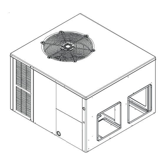
These installation instructions cover the outdoor
installation of self contained package air conditioners
and heating units. See the Specification Sheets
applicable to your model for information regarding
accessories.
is a registered trademark of Maytag Corporation or its related companies and is used under license. All rights reserved.
IOA-3013
02/2015
I
NSTALLATION
F
S
-C
OR
ELF
H
EAT
APH16 "M" SERIES
Affix this manual and Users Information Manual adjacent to the unit.
RECOGNIZE THIS SYMBOL AS A SAFETY PRECAUTION.
ATTENTION INSTALLING PERSONNEL
installation or repair, caution is to be observed.
Goodman Manufacturing Company, L.P.
5151 San Felipe, Suite 500, Houston, TX 77056
www.goodmanmfg.com
© 2015 Goodman Manufacturing Company, L.P.
I
NSTRUCTIONS
P
ONTAINED
P
U
UMP
NITS
*NOTE: Please contact your distributor or our
Specification Sheets referred to in this manual.
www.amana-hac.com
ACKAGE
website for the applicable
Advertisement
Table of Contents

Subscribe to Our Youtube Channel
Related Manuals for Amana APH16 M Series


Summary of Contents for Amana APH16 M Series
- Page 1 Maytag Corporation or its related companies and is used under license. All rights reserved. Goodman Manufacturing Company, L.P. IOA-3013 5151 San Felipe, Suite 500, Houston, TX 77056 www.goodmanmfg.com www.amana-hac.com 02/2015 © 2015 Goodman Manufacturing Company, L.P.
-
Page 2: Table Of Contents
INDEX SHIPPING INSPECTION ..............................4 REPLACEMENT PARTS ............................... 4 ................................4 RDERING ARTS SAFETY INSTRUCTIONS ..............................4 CODES AND REGULATIONS ............................... 5 EPA R ................................5 EGULATIONS ................................5 ATIONAL ODES MAJOR COMPONENTS ............................... 5 PRE-INSTALLATION CHECKS ............................. 5 ............................5 LEARANCES AND CCESSIBILITY .................................. - Page 3 MAINTENANCE .................................. 14 SERVICE .................................... 15 ............15 OMMON AUSES OF NSATISFACTORY PERATION OF UMP ON THE EATING YCLE ....................15 NADEQUATE OLUME HROUGH NDOOR ........................15 UTSIDE IR INTO ETURN .............................. 15 NDERCHARGE “T ” S ......................15 ERMINATING ENSOR CONTACT : ................
-
Page 4: Shipping Inspection
NSTALLER Carefully read all instructions for the installation prior to installing unit. Make sure each step or procedure is understood and any special considerations are taken into account before starting installation. Assemble all tools, hardware and supplies needed to complete the installation. Some items may need to be purchased locally. -
Page 5: Codes And Regulations
Rated performance is achieved after 72 hours of operation. Rated performance is delivered at the specified airflow. See outdoor unit specification sheet for split system models or product specification sheet for packaged and light commercial models. Specification sheets can be found at www.amana- ®... -
Page 6: Ground Level Pre -Installation Details
ROUND EVEL NSTALLATION ETAILS The unit should be set on a solid, level foundation - preferably a concrete slab at least 4 inches thick. The slab should be above ground level and surrounded by a graveled area for good drainage. Any slab used as a unit’s foundation should not adjoin the building as it is possible that sound and vibration may be transmitted to the structure. -
Page 7: Rigging Details
IGGING ETAILS Rigging IMPORTANT: If using bottom discharge with roof curb, duct work should be attached to the curb prior to installing the unit. Lower unit carefully onto roof mounting curb. While rigging unit, center of gravity will cause condenser end to be lower than supply air end. -
Page 8: Piping
cleaning. When installing filters, ensure the air flow arrows on the filter MINIMUM FILTER SIZE are pointing toward the circulator blower. NOMINAL SIZE (INCHES) NOMINAL AREA (SQ. FT.) Refer to the unit filter size chart below for filter size information. 10x20 14x20 14x25... -
Page 9: Low Voltage Wiring
OLTAGE IRING APH1624-48 • Heat Pumps. Connect 24V wires from the thermostat to the Terminal Thermostat corresponding wires in the control box using No. 18 AWG as follows: R (24V) NOTE: All APH16 units have two-stage cooling and require two-stage Green G (fan) heat/cool with optional third stage electric heat thermostat. -
Page 10: Final System Checks
4. If the outdoor ambient is above 80°F, the unit may trip on its high pressure cut out when on heating. The compressor should stop. The heating cycle must be thoroughly checked, so postpone the test to another day when conditions are more suitable. DO NOT FAIL TO TEST. -
Page 11: Heat Pump Operation
Indoor Blower Motor This is activated by the room thermostat by COOLING or FAN ON position. For APH models, the motor is energized by the fan control board for ECM motors. ECM motors are constant CFM motors with very low power consumption. This motor is energized by a 24V signal from the thermostat. -
Page 12: Air Flow Measurement And Adjustment
Suggested Field Testing/Trouble Shooting 1. Run unit in the heating mode (room thermostat calling for heat). 2. Check unit for proper charge. NOTE: Bands of frost on the condenser coil indicate low refrigerant charge. 3. Shut off power to unit. 4. -
Page 13: Aph Humidity Control
APH H UMIDITY ONTROL When using a Humidistat (normally closed), cut jumper PJ6 on the control board. The Humidistat will only affect both low stage and high stage cooling air flow by adjusting the Air flow to 85%. APH T TAGE EATING When using staged electric heat, cut jumper PJ4 on the control board. -
Page 14: System Charging Heating Mode
d. If subcooling is high and superheat is low, adjust TXV valve superheat and remove charge to lower the subcooling. NOTE: Do NOT adjust the charge based on suction pressure unless there is a gross undercharge. 4. Disconnect manifold set, installation is complete. Refrigerant Charge Check (Units with Fixed Orifice Devices) After completing airflow measurements and adjustments the unit’s Design Superheat &... -
Page 15: Service
SERVICE THE FOLLOWING INFORMATION IS FOR USE BY QUALIFIED SERVICE AGENCY ONLY: OTHERS SHOULD NOT ATTEMPT TO SERVICE THIS EQUIPMENT. OMMON AUSES OF NSATISFACTORY PERATION OF UMP ON THE EATING YCLE NADEQUATE OLUME HROUGH NDOOR When a heat pump is in the heating cycle, the indoor coil is functioning as a condenser. The return air filter must always be clean, and sufficient air volume must pass through the indoor coil to prevent excessive discharge pressure, and high pressure cut out. -
Page 16: Appendix
APPENDIX... -
Page 17: Troubleshooting Chart
TROUBLESHOOTING CHART HIGH VOLTAGE! Disconnect ALL power before servicing or installing this unit. Multiple power sources may be present. Failure to do so may cause property damage, personal injury or death. POSSIBLE CAUSE REMEDY SYMPTOM High head - low suction a. -
Page 18: Aph16 Blower Performance Data
APH16 BLOWER PERFORMANCE DATA APH1624M41 APH1630M41 Cooling/HP Adjust Electric Adjust Cooling/HP Adjust Electric Adjust CFM* CFM* CFM* CFM* Speed Heat Speed Heat Minus Minus Minus Minus Normal Normal Normal Normal Plus Plus Plus Plus Minus Minus Minus Minus Normal Normal Normal 1,000 Normal... -
Page 19: Aph16 Cfm Output And Dip Switch Settings
APH16 CFM OUTPUT AND DIP SWITCH SETTINGS CFM Output CFM Output for DIP Switch Combinations 1-2 (Electric Heat) for DIP Switch Combinations 5-6 (Cooling/Heating). SPEED SWITCH SWITCH COOLING/HP SPEED SW ITCH SW ITCH ELECTRIC MODEL MODEL HEAT (CFM) 1050 1050 APH1624 APH1624 1250... -
Page 20: Minimum Clearances
DIMENSIONS POWER WIRE ENTRANCE 4 1/8 2 1/8 1 3/8 5 ½ 6 ½ 2 34 BLOWER ACCESS PANEL RETURN SUCTION/LIQUID PRESSURE PORT SUPPLY CONDENSATE DRAIN CONTROL 18 7/8 CONNECTION WIRE 3/4” NPT FEMALE ENTRANCE MEDIUM CHASSIS APH1624M41* APH1630M41* APH1636M41* LARGE CHASSIS APH1642M41* APH1648M41*... -
Page 21: Start-Up Checklist
Start-up Checklist *Store in job file Date: ___________________________________ Location: __________________________________________ Model Number: ___________________________________ __________________________________________ Serial Number: ___________________________________ __________________________________________ Technician: ___________________________________ Unit #: __________________________________________ Pre Start-Up (Check each item as completed) Verify all packaging material has been removed. Remove all shipping brackets per installation instructions. Verify the job site voltage agrees with the unit serial plate. - Page 22 Start-up Checklist Start-Up (Insert the values as each item is completed.) ELECTRICAL Supply Voltage L1 - L2 L2 - L3 L3 - L1 Circuit 1 Compressor Amps Circuit 2 Compressor Amps Blower Amps Condenser Fan Amps Fan 1 Fan 2 Fan 3 BLOWER EXTERNAL STATIC PRESSURE Return Air Static Pressure...
- Page 23 THIS PAGE LEFT INTENTIONALLY BLANK...
- Page 24 Goodman Manufacturing Company, L.P. 5151 San Felipe, Suite 500, Houston, TX 77056 www.goodmanmfg.com www.amana-hac.com © 2015 Goodman Manufacturing Company, L.P.
Need help?
Do you have a question about the APH16 M Series and is the answer not in the manual?
Questions and answers