Advertisement
Quick Links
Service and Troubleshooting
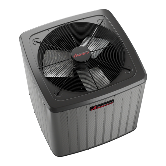
ALXS3, ALXS4, ALXS5, GLXS3, GLXS4, GLXS5 Condensing Units.
Pride and workmanship go into every product to provide
our customers with quality products. It is possible, however,
that during its lifetime a product may require service.
Products should be serviced only by a qualified service
technician who is familiar with the safety procedures
required in the repair and who is equipped with the proper
tools, parts, testing instruments and the appropriate service
manual. REVIEW ALL SERVICE INFORMATION IN THE
APPROPRIATE SERVICE MANUAL BEFORE
BEGINNING REPAIRS.
ONLY PERSONNEL THAT HAVE BEEN TRAINED TO INSTALL,
ADJUST, SERVICE, MAINTENANCE OR REPAIR
(HEREINAFTER, "SERVICE") THE EQUIPMENT SPECIFIED IN
THIS MANUAL SHOULD SERVICE THE EQUIPMENT.
THIS EQUIPMENT IS NOT INTENDED FOR USE BY
PERSONS (INCLUDING CHILDREN) WITH REDUCED
PHYSICAL, SENSORY OR MENTAL CAPABILITIES, OR LACK
OF EXPERIENCE AND KNOWLEDGE, UNLESS THEY HAVE
BEEN GIVEN SUPERVISION OR INSTRUCTION CONCERNING
USE OF THE APPLIANCE BY A PERSON RESPONSIBLE FOR
THEIR SAFETY.
CHILDREN SHOULD BE SUPERVISED TO ENSURE THAT
THEY DO NOT PLAY WITH THE EQUIPMENT.
THE MANUFACTURER WILL NOT BE RESPONSIBLE FOR
ANY INJURY OR PROPERTY DAMAGE ARISING FROM
IMPROPER SUPERVISION, SERVICE OR SERVICE
PROCEDURES. IF YOU SERVICE THIS UNIT, YOU ASSUME
RESPONSIBILITY FOR ANY INJURY OR PROPERTY
DAMAGE WHICH MAY RESULT. IN ADDITION, IN
JURISDICTIONS THAT REQUIRE ONE OR MORE LICENSES
TO SERVICE THE EQUIPMENT SPECIFIED IN THIS
MANUAL, ONLY LICENSED PERSONNEL SHOULD SERVICE
THE EQUIPMENT. IMPROPER SUPERVISION, INSTALLATION,
ADJUSTMENT, SERVICING, MAINTENANCE OR REPAIR OF
THE EQUIPMENT SPECIFIED IN THIS MANUAL, OR
ATTEMPTING TO INSTALL, ADJUST, SERVICE OR REPAIR
THE EQUIPMENT SPECIFIED IN THIS MANUAL WITHOUT
PROPER SUPERVISION OR TRAINING MAY RESULT IN
PRODUCT DAMAGE, PROPERTY DAMAGE, PERSONAL
INJURY OR DEATH.
Brand is a registered trademark of Maytag Corporation or its related companies and is used under license. All rights reserved.
®
ALZS4, ALZS5, GLZS4, GLZS5 Heat Pumps
With Refrigerant Blowers, Coils, & Accessories
WARNING
©2019-2024 Daikin Comfort Technologies Manufacturing, L.P.
Do not bypass safety devices.
All maintenance staff and others working in the local area
shall be instructed on the nature of work being carried out.
Work in confined spaces shall be avoided.
No person carrying out work in relation to a REFRIGERATING
SYSTEM which involves exposing any pipe work shall use
any sources of ignition in such a manner that it may lead to
the risk of fire or explosion. All possible ignition sources,
including cigarette smoking, should be kept sufficiently far
away from the site of installation, repairing, removing and
disposal, during which refrigerant can possibly be released
to the surrounding space. Prior to work taking place, the
area around the equipment is to be surveyed to make sure
that there are no flammable hazards or ignition risks. "No
Smoking" signs shall be displayed.
WARNING
WARNING
WARNING
RS6200301r1
August 2024
Advertisement

Subscribe to Our Youtube Channel
Related Manuals for Amana ALXS3


Summary of Contents for Amana ALXS3
- Page 1 Service and Troubleshooting ALXS3, ALXS4, ALXS5, GLXS3, GLXS4, GLXS5 Condensing Units. ALZS4, ALZS5, GLZS4, GLZS5 Heat Pumps With Refrigerant Blowers, Coils, & Accessories Pride and workmanship go into every product to provide our customers with quality products. It is possible, however, that during its lifetime a product may require service.
- Page 2 IMPORTANT INFORMATION SYSTEM EVACUATION ..........35 TABLE OF CONTENTS DEEP VACUUM METHOD ........36 TRIPLE RVACUATION METHOD ......36 IMPORTANT INFORMATION ..........2 CHARGING ...............37 PRODUCT IDENTIFICATION ..........5 FINAL CHARGE ADJUSTMENT ......38 PRODUCT DESIGN ............10 FIXED ORFICES ............40 SYSTEM OPERATION ...........13 EXPANSION VLAVE SYSTEM ........40 SERVICING ..............16 SUPERHEAT ADJUSTMENT ........40 CHECKING VOLTAGE ..........16...
- Page 3 IMPORTANT INFORMATION IMPORTANT NOTICES WARNING RECOGNIZE SAFETY SYMBOLS, WORDS AND To avoid possible injury, explosion or death, practice safe LABELS handling of refrigerants. WARNING To prevent the risk of property damage, personal injury, of WARNING death, do not store combustible materials or use gasoline or other flammable liquids or vapors in the vicinity of this The compressor POE oil for units is extremely...
- Page 4 The manual contains specific information for service The following checks shall be applied to installations using personnel FLAMMABLE REFRIGERANTS: Checks to the area • the actual REFRIGERANT CHARGE is in accordance Prior to beginning work on systems containing with the room size within which the refrigerant FLAMMABLE REFRIGERANTS, safety checks are containing parts are installed;...
- Page 5 PRODUCT IDENTIFICATION NOMENCLATURE...
- Page 6 PRODUCT IDENTIFICATION NOMENCLATURE...
- Page 7 PRODUCT IDENTIFICATION NOMENCLATURE...
- Page 8 PRODUCT IDENTIFICATION NOMENCLATURE...
- Page 9 Initial release of Amana® Brand 14.6-15.9 S EE R2 AC R32 ( All Regions) ALZS 4BA**10AA Initial release of Amana® Brand 13.8-14.5 S E E R2 HP R32 ( All Regions) ALZS 4NA**10AA Initial release of Amana® Brand 13.8-14.5 S E E R2 HP R32 (North) ALZS 5BA**10AA Initial release of Amana®...
- Page 10 PRODUCT DESIGN This section gives a basic description of cooling unit This appliance can be installed in the vertical or left operation, its various components and their basic horizontal position without modification. The horizontal right operation. Ensure your system is properly sized for heat and downflow positions require product modification.
- Page 11 PRODUCT DESIGN • “Ultratech” Series scroll compressors use “POE” or polyolester oil which is NOT compatible with mineral oil based lubricants like 3GS. “POE” oil must be used if additional oil is required. • Compliant scroll compressors perform “quiet” shutdowns that allow the compressor to restart immediately without the need for a time delay.
- Page 12 PRODUCT DESIGN Unloader Solenoid A nominal 24-volt direct current coil activates the internal unloader solenoid. The input control circuit voltage must be 18 to 28 volt ac. The coil power requirement is 20 VA. The external electrical connection is made with a molded plug assembly.
- Page 13 SYSTEM OPERATION Cooling Cycle For heat pumps, during cooling cycle the reversing valve is For legacy room thermostat: When the room thermostat energized as the room thermostat closes “O” terminal to R calls for cool, the contacts of the room thermostat close and the microprocessor on the UC board responds to such making terminals R to Y1 &...
- Page 14 SYSTEM OPERATION Heating Cycle This draws in the normally open contact CC, starting the Reversing Valve The reversing valve on the models is energized in the compressor condenser fan motors. At the same time, (Energized) cooling cycle through the “O” terminal on the room contacts RFC close, starting the indoor fan motor.
- Page 15 Operation Operation Most expansion valves used in current Amana Brand Heat Pump products use an internally checked expansion valve. This type of expansion valve does not require an external check valve as shown above. Restrictor Orifice Assy in Cooling Operation...
- Page 16 SERVICING Checking Voltage Checking Wiring 1. Remove outer case, control panel cover, etc., from unit WARNING being tested. With power ON: High Voltage! Disconnect all power before servicing or installing. Multiple power sources may be present. WARNING Failure to do so may cause property damage, personal injury or death.
- Page 17 SERVICING Resistance Heaters Checking Contactor And/Or Relays 1. Set room thermostat to a higher setting than room WARNING temperature so both stages call for heat. 2. With voltmeter, check for 24 volts at each heater relay. 3. No voltage indicates the trouble is in the thermostat or High Voltage! Disconnect all power before servicing or wiring.
- Page 18 SERVICING Checking Fan Relay Contacts Test 1. Testing High Pressure Control in Cooling Mode 1. Connect refrigerant gages to unit. WARNING 2. Disconnect power to outdoor unit. 3. Remove control panel cover. 4. Disconnect black wire from condenser fan motor High Voltage! Disconnect all power before servicing or (single stage units) or remove plug from control board...
- Page 19 (close) at approximately 50 PSIG. 7. If low pressure switch does not operate in these parameters replace switch. Copeland Coresense™ Diagnostics - 3-Wire module Applies to Amana Brand ALXS and ALZS units WARNING High Voltage! Disconnect all power before servicing or installing.
- Page 20 SERVICING Once attached, CoreSense™ provides around-the-clock monitoring for common electrical problems, compressor defects and broad system faults. If a glitch is detected, an LED indicator flashes the proper alert codes to help you quickly pinpoint the problem. See Diagnostic Table: 2-Wire Comfort Alert™...
- Page 21 SERVICING Diagnostics Table: Coresense™ Module Flash code number corresponds to the number of LED flashes, followed by a pause and then repeated. TRIP and ALERT LEDs flashing at the same time mean control circuit voltage is too low for operation. Status Description Troubleshooting Information...
- Page 22 SERVICING Diagnostics Table: Coresense™ Module Flash code number corresponds to the number of LED flashes, followed by a pause and then repeated. TRIP and ALERT LEDs flashing at the same time mean control circuit voltage is too low for operation. Status Description Troubleshooting Information...
- Page 23 SERVICING Table 1 - Quick Reference Table Alert Code Alert Condition Lock Level Lock Indication Normal Run Normal operation, no trip Solid Yellow Code1 Long run time. Compressor is on running for more than 18 Yellow Flash 1 hours. (Code1 is disabled in Heat Pump mode.) Compressor (pressure) trip.
- Page 24 Only hard start kits approved by Amana® brand or Copeland should be used. “Kick Start” and/or “Super Boost” kits are not approved start assist devices.
- Page 25 SERVICING To prevent the compressor from short cycling, a Time Delay LEAK DETECTION SYSTEM INSTALLED. UNIT MUST BE Relay (Cycle Protector) has been added to the low voltage POWERED EXCEPT FOR SERVICE. circuit. RED LED'S STATUS (REFER I/O FOR RECOMMENDED ACTION) Testing a Run Capacitor Under Load MODE...
- Page 26 SERVICING RED LED'S STATUS MODE Definition LED Flashing Pattern Recommended actions Notes: Slow LED flashing pattern Normal Operation No faults to report No action (2 seconds on and 2 seconds off) R32 leak is The controls and sensor are working R32 Leak Alarm currently being Fast LED Flashing Pattern...
- Page 27 SERVICING Checking High Efficiency Motors Instruction to replace A2L PCB: Take off the blower access panel, disconnect the PCB The motor is a one piece, fully encapsulated, 3 phase harness and R32 sensor wire connected to the PCB, brushless DC (single phase AC input) motor with ball detach the defective PCB from the 4 plastic standoffs, bearing construction.
- Page 28 SERVICING EEM Blower Replacement For New AWST/AWSF R32 Air Handlers. 1. Disconnect power at main electrical panel. 2. Remove front access panel. 3. Remove the two screws on each side holding the lower control box and move out of the way to give access to the blower assembly 6.
- Page 29 SERVICING Resistance Test Each compressor is equipped with an internal overload. The line break internal overload senses both motor amperage and winding temperature. High motor temperature or amperage heats the disc causing it to open, breaking the common circuit within the compressor on single phase units.
- Page 30 SERVICING If either winding does not test continuous, replace the compressor. NOTE: If an open compressor is indicated, allow ample time for the internal overload to reset before replacing compressor. Ground Test If fuse, circuit breaker, ground fault protective device, etc., has tripped, this is a strong indication that an electrical problem exists and must be found and corrected.
- Page 31 SERVICING 3. If clicks can’t be heard, shut off power to the unit and remove the control circuit molded plug from the WARNING compressor and measure the unloader coil resistance (connections on the compressor). The solenoid coil Line voltage now present. should have continuity and not be grounded or have •...
- Page 32 SERVICING Troubleshooting the Reversing Valve for If voltage is registered at the coil, tap the valve body lightly while switching the system from HEATING to COOLING, Electrical Failure etc. If this fails to cause the valve to switch positions, 1. Place unit into the cooling mode. Test for 24 volts at the remove the coil connector cap and test the continuity of solenoid.
- Page 33 SERVICING 4. Check the temperature at which the control opens its The system CFM can be determined by measuring the contacts by raising the temperature of the control. Part static pressure external to the unit. The installation manual #0130M00009P which is used on 2 and 2.5 ton units supplied with the blower coil, or the blower performance should open at 60°F ±...
- Page 34 SERVICING WARNING TEMPERATURE RISE (°F) @ 240V 14.4 19.2 24.0 28.8 High Voltage! Disconnect all power before servicing or installing. Multiple power sources may be present. Failure to do so may cause property damage, personal injury or death. 1. Remove the wiring from the control terminals. 1000 2.
- Page 35 SERVICING 2. Plug or cap all openings. Using dry nitrogen, pressurize the system to 450 PSIG. 3. Remove all burrs and clean the brazing surfaces of the Allow the pressure to stabilize and hold for 15 minutes tubing with sand cloth or paper. Brazing materials do (minimum).
- Page 36 SERVICING CAUTION 5000 4500 Prolonged operation at suction pressures less than 20 psig 4000 for more than 5 seconds will result in overheating of the LEAK(S) scrolls and permanent damage to the scroll tips, drive 3500 PRESENT bearings and internal seal. 3000 2500 Deep Vacuum Method (Recommended)
- Page 37 SERVICING Charging NOTE: These are not back-seating valves. It is not necessary to force the stem tightly against the rolled WARNING lip. REFRIGERANT UNDER PRESSURE! Break vacuum by fully opening liquid service valve. • Do not overcharge system with refrigerant. •...
- Page 38 SERVICING 1. 3/8” valve to 5 - 10 in-lbs NOTE: Superheat adjustments should not be made until indoor ambient conditions have stabilized. 2. 5/8” valve to 5 - 20 in-lbs 3. 3/4” valve to 5 - 20 in-lbs This could take up to 24 hours depending on indoor 4.
- Page 39 SERVICING SATURATED SUCTION PRESSURE SATURATED LIQUID PRESSURE TEMPERATURE CHART TEMPERATURE CHART LIQUID SATURATED SUCTION SUCTION SATURATED SUCTION PRESSURE TEMPERATURE ºF PRESSURE TEMPERATURE ºF PSIG R-32 PSIG R-32 NOTE: Specifications And Performance Data Listed Herein Are Subject To Change Without Notice.
- Page 40 SERVICING Superheat Adjustment Fixed Orifice 1. Purge gauge lines. Connect service gauge manifold NOTE: Units matched with indoor coils equipped with a to base-valve service ports. Run system at least 10 TXV should be charged by Subcooling only. minutes to allow pressure to stabilize. 2.
- Page 41 SERVICING The condition of the scroll flanks is checked in the following Superheat Settings for Expansion Valve Systems manner. SC at Tonnage SH at Compressor OD Liq 1. Attach gauges to the high and low side of the system. 1.5-2.5T 10-14°F 7-9°F 2.
- Page 42 If the pressure indicates a higher temperature than that NOTE: The Flushing Method using R-11 refrigerant of the coil temperature, non-condensables are present. is no longer approved by Amana® Brand Heating- Cooling. Non-condensables are removed from the system by first removing the refrigerant charge, replacing and/or installing liquid line drier, evacuating and recharging.
- Page 43 SERVICING Suction Line Drier Clean-Up Method POE oils maintain a consistent viscosity over a large temperature range which aids in the oil return to the The POE oils used with R32 refrigerant is an excellent compressor; however, there will be some installations solvent.
- Page 44 SERVICING Furnace External Static Pressure To determine proper airflow, proceed as follows: 1. With clean filters in the furnace, using a Inclined Manometer or Magnehelic gauge measure the static pressure of the return duct at the inlet of the furnace (Negative Pressure).
- Page 45 SERVICING 2. Using garden hose, spray coil vertically downward with The refrigerant charge shall only be recovered into constant stream of water at moderate pressure. Keep a cylinder labeled for use with R-32. Ensure that the nozzle at a 15 to 20° angle, about 3 in. from coil face. refrigerant cylinder(s) are capable of holding the total Spray so debris is washed out of coil and base pan.
- Page 46 SERVICING • recovery equipment and cylinders conform to the appropriate standards. d. Pump down refrigerant system, if possible. e. If a vacuum is not possible, make a manifold so that refrigerant can be removed from various parts of the system. Make sure that cylinder is situated on the scales before recovery takes place.
- Page 47 Troubleshooting Air Handler - EEM Motor EEM Motor Equipped Air Handler 240 volts at EEM Check breaker or fuses and motor on terminals wiring L & N Check for 24 volts Make sure thermostat is calling between C & and for fan operation.
- Page 48 Troubleshooting Auxiliary Electric - Heating No Heat 240 Volts at Check Power Check indoor Panel Breakers or at Disconnect Contactors Check wiring Replace breaker or wiring to Breaker or Contactor Proceed to low voltage check 24 Volts at Replace Transformer transformer 24 Volts on W Check Thermostat and Wiring...
- Page 49 Troubleshooting Condenser - Cooling No Cool Wiring to Contactor Compressor Repair or Replace Wiring Compressor Open Running Run Capacitor Replace Capacitor Good Compressor Compressor Check for Locked Compressor Overload Windings Open Open Replace Compressor Compressor Replace Compressor Warm to Touch Did Compressor Replace Compressor Restart After...
- Page 50 Troubleshooting Heat Pump - Cooling (1 Stage) No Cool Wiring to Compressor Contactor Repair or Replace Wiring Compressor Running Open Run Capacitor Replace Capacitor Good Compressor Compressor Check for Stuck Compressor Overload Windings Open Open Replace Compressor Compressor Replace Compressor Warm to Touch Did Compressor...
- Page 51 Troubleshooting Heat Pump - Cooling (1 Stage) Repair or replace Metering Metering Device Device Working Properly Check for proper charge. Check subcooling and/or superheat...
- Page 52 Troubleshooting Heat Pump - Heating (1 Stage) No Heat Wiring to Compressor Contactor Repair or Replace Wiring Compressor Running Open Run Capacitor Replace Capacitor Good Compressor Compressor Check for Stuck Compressor Overload Windings Open Open Replace Compressor Compressor Replace Compressor Warm to Touch Did Compressor...
- Page 53 Troubleshooting Heat Pump - Heating (1 Stage) Check Thermostat and Thermostat in Thermostat Wires Cool Mode Switch Thermostat to Heat Mode...
- Page 54 WIRING DIAGRAMS ALXS3BN**10AA/ALXS4BA**10AA Wiring is subject to change. Always refer to the wiring diagram on the unit for the most up-to-date wiring.
- Page 55 WIRING DIAGRAMS ALXS460NA10AA Wiring is subject to change. Always refer to the wiring diagram on the unit for the most up-to-date wiring.
- Page 56 WIRING DIAGRAMS ALXS560BA10AA Wiring is subject to change. Always refer to the wiring diagram on the unit for the most up-to-date wiring.
- Page 57 WIRING DIAGRAMS ALZS4**BA10AA Wiring is subject to change. Always refer to the wiring diagram on the unit for the most up-to-date wiring.
- Page 58 WIRING DIAGRAMS ALZS60BA10AA Wiring is subject to change. Always refer to the wiring diagram on the unit for the most up-to-date wiring.
- Page 59 WIRING DIAGRAMS ALZS4**NA10AA Wiring is subject to change. Always refer to the wiring diagram on the unit for the most up-to-date wiring.
- Page 60 WIRING DIAGRAMS AMST24-48*U1300AA Wiring is subject to change. Always refer to the wiring diagram on the unit for the most up-to-date wiring.
- Page 61 WIRING DIAGRAMS AMST60*U1300AA Wiring is subject to change. Always refer to the wiring diagram on the unit for the most up-to-date wiring.
- Page 62 WIRING DIAGRAMS ACSF18-301300AA Wiring is subject to change. Always refer to the wiring diagram on the unit for the most up-to-date wiring.
- Page 63 WIRING DIAGRAMS AWST/AWSF18-24**1300AA Wiring is subject to change. Always refer to the wiring diagram on the unit for the most up-to-date wiring.
- Page 64 WIRING DIAGRAMS AWST/AWSF30**1300AA Wiring is subject to change. Always refer to the wiring diagram on the unit for the most up-to-date wiring.
- Page 65 WIRING DIAGRAMS AWST/AWSF36**1300AA Wiring is subject to change. Always refer to the wiring diagram on the unit for the most up-to-date wiring.
- Page 66 WIRING DIAGRAMS GLXS3BN**10AA/GLXS4**BA10AA Wiring is subject to change. Always refer to the wiring diagram on the unit for the most up-to-date wiring.
- Page 67 WIRING DIAGRAMS GLXS418-48BA Wiring is subject to change. Always refer to the wiring diagram on the unit for the most up-to-date wiring.
- Page 68 WIRING DIAGRAMS GLXS560BA10AA Wiring is subject to change. Always refer to the wiring diagram on the unit for the most up-to-date wiring.
- Page 69 WIRING DIAGRAMS GLZS4**BA/GLSZ4MA**10AA Wiring is subject to change. Always refer to the wiring diagram on the unit for the most up-to-date wiring.
- Page 70 WIRING DIAGRAMS GLZS560BA10AA Wiring is subject to change. Always refer to the wiring diagram on the unit for the most up-to-date wiring.
Need help?
Do you have a question about the ALXS3 and is the answer not in the manual?
Questions and answers