
Related Manuals for Kenwood TM-D710GE


Summary of Contents for Kenwood TM-D710GE
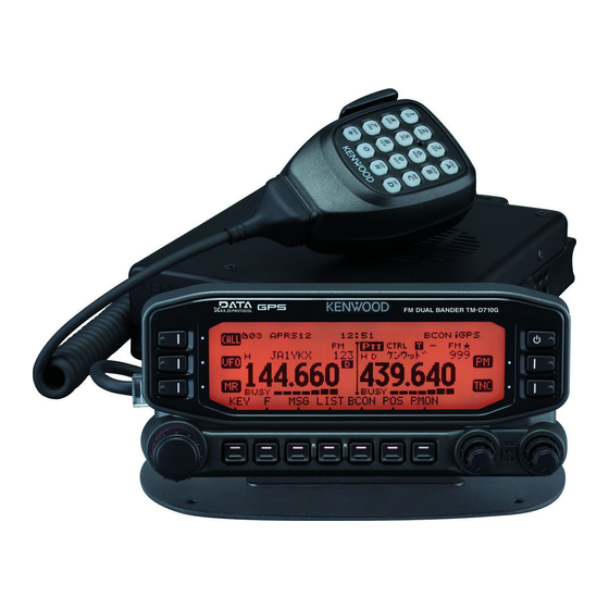
- Page 1 INSTRUCTION MANUAL 144/440 MHz FM DUAL BANDER TM-D710GA 144/430 MHz FM DUAL BANDER TM-D710GE Version: 1.01 ©...
-
Page 2: Table Of Contents
CONTENTS OPERATING THROUGH REPEATERS ......................REPEATER- REPEATER ACCESS ..............................1 Selecting an Offset Direction ............................ 1 Selecting an Offset Frequency ..........................1 Activating the Tone Function ............................ 1 Selecting a Tone Frequency ............................. 2 Automatic Repeater Offset ............................2 TRANSMITTING A 1750 Hz TONE ..........................3 REVERSE FUNCTION .............................. - Page 3 Using Visual Scan ..............................4 CTCSS/ DCS/ CROSS TONE ..........................SIGNALING- USING CTCSS ................................1 CTCSS FREQUENCY SCAN ............................2 USING DCS .................................. 2 DCS CODE SCAN ................................ 3 USING CROSS TONE ..............................3 Selecting a Cross Tone mode ........................... 3 DUAL TONE MULTI-FREQUENCY (DTMF) ......................DTMF- MANUAL DIALING ................................
- Page 4 Microphone Keys ..............................5 Frequency Direct Entry ............................. 5 KEY LOCK ..................................5 Microphone Key Lock ............................... 5 AUTOMATIC POWER OFF (APO) ..........................6 PC PORT SPEED ................................. 6 DISPLAY PARTITION BAR ............................6 POWER ON PASSWORD ............................. 6 GPS (GLOBAL POSITIONING SYSTEM) ........................ GPS-1 INTERNAL GPS FUNCTION ON/OFF ..........................
- Page 5 DISPLAY FILTER FUNCTION ............................6 RECEIVING A MESSAGE ............................. 6 ENTERING A MESSAGE .............................. 7 ACCESSING RECEIVED APRS MESSAGES ......................7 TRANSMITTING A MESSAGE ............................. 8 BASIC SETTINGS ................................. 8 My Callsign <MY CALLSIGN> ..........................8 Beacon Type <BEACON TYPE> ..........................8 APRS Lock <APRS LOCK>...
- Page 6 NETWORK ..................................15 VOICE ALERT ................................15 WEATHER STATION DATA OUTPUT ..........................16 Transmit <TX> ................................16 Transmit Interval Time <TX INTERVAL> ........................16 SETTING AS A DIGIPEATER ............................16 DIGIPEAT ................................. 16 UICHECK ................................. 16 UIDIGI ..................................16 UIFLOOD ................................. 17 UITRACE ..................................
- Page 7 TRANSCEIVER RESET ............................RESET- KEY OPERATION ................................. 1 MENU MODE ................................1 VGS-1 (OPTIONAL) OPERATION ..........................VGS- VOICE ANNOUNCEMENTS ............................1 Voice Announcement Language ..........................2 Voice Announcement Volume ........................... 2 Voice Announcement Speed ............................ 2 VOICE RECORDER ..............................2 Voice Memos ................................
-
Page 8: Operating Through Repeaters
OPERATING THROUGH REPEATERS Repeaters are often installed and maintained by radio clubs, sometimes with the cooperation of local businesses involved in the communications industry. Compared to simplex communication, you can usually transmit over much greater distances by using a repeater. Repeaters are typically located on mountain tops or other elevated locations. -
Page 9: Selecting A Tone Frequency
– 5 MHz offset 82.5 136.5 225.7 450.000 MHz and higher: No offset 85.4 141.3 229.1 (Simplex operation) 88.5 146.2 233.6 TM-D710GE 91.5 151.4 241.8 Under 145.600 MHz: No offset 94.8 156.7 250.3 (Simplex operation) 97.4 162.2 254.1 145.600 ~ 145.799 MHz: –... -
Page 10: Transmitting A 1750 Hz Tone
TRANSMITTING A 1750 Hz TONE Note: ◆ Pressing [PTT] will cause the icon to stop blinking. ◆ Most repeaters in Europe require that a transceiver transmit a ASC does not function if you are using simplex operation. ◆ 1750 Hz tone. On a E type model, simply pressing Microphone ASC does not function while scanning. -
Page 11: Memory Channels
MEMORY CHANNELS In Memory channels, you can store frequencies and related data that you often use. Then you need not reprogram the data every time. You can quickly recall a programmed channel by simple operation. A total of 1000 Memory channels are available for bands A and B. SIMPLEX &... -
Page 12: Storing Odd-Split Repeater Frequencies
STORING ODD-SPLIT REPEATER FREQUENCIES RECALLING A MEMORY CHANNEL Press [MR] to enter Memory Recall mode. Some repeaters use a receive and transmit frequency pair with a non-standard offset. To access those repeaters, store Rotate the Tuning control to select your desired Memory two separate frequencies in a memory channel. -
Page 13: Naming A Memory Channel
NAMING A MEMORY CHANNEL CHANNEL DISPLAY FUNCTION You can name Memory channels using up to 8 characters. When Use this function when you want to use only Memory channels. you recall a named Memory channel, its name appears on the When this function is switched ON, the transceiver displays only display. - Page 14 Key Name [KEY] [F], [KEY] [KEY] (1s) While Transmitting [KEY] + Power ON Power ON/OFF Power ON/OFF Power ON/OFF Power ON/OFF – – – – – DX PacketClusters – – – – Monitor ON/OFF CALL Call mode – Call Scan –...
-
Page 15: Programmable Memory (Pm)
PROGRAMMABLE MEMORY (PM) Programmable Memory (PM) stores virtually all settings currently set on the transceiver. This transceiver provides 5 PM channels to store 5 sets of transceiver confi gurations. Later, you can quickly recall any one of these channels, depending on the operations you have in mind or the operating environment. -
Page 16: Storing Data In Pm Channels
PM CHANNEL RESET STORING DATA IN PM CHANNELS To reset the PM channels to their default settings: 1 Confi rm that the following conditions have been satisfi ed: • The transceiver is in receive mode. 1 Turn the transceiver power OFF. •... -
Page 17: Scan
SCAN Scan is a useful feature for hands-off monitoring of your favorite frequencies. Becoming comfortable with all types of Scan will increase your operating effi ciency. This transceiver provides the following types of scans: Scan Type Scan Range VFO Scan Scans all frequencies on the current band. -
Page 18: Vfo Scan
VFO SCAN GROUP SCAN VFO Scan monitors all frequencies tunable on the band, using For the purpose of Group Scan, the 1000 Memory channels are the current frequency step size. divided into 10 groups, with each group containing 100 channels. Group Scan monitors only the 100 channels which belong to the 1 Select your desired band. -
Page 19: Program Scan
■ Using Program Scan PROGRAM SCAN 1 Select your desired band. Program Scan is identical to VFO Scan except that you select a frequency range for the scan. 2 Press [VFO]. 3 Rotate the Tuning control to select a frequency within ■... -
Page 20: Visual Scan
VISUAL SCAN Note: ◆ You cannot use the Visual Scan Function under the following circumstances: While you are receiving, Visual Scan allows you to monitor • When the APRS/NAVITRA or Packet mode is turned frequencies near the current operating frequency. Visual Scan graphically and simultaneously shows how all frequencies in the •... -
Page 21: Ctcss/ Dcs/ Cross Tone
CTCSS/ DCS/ CROSS TONE CTCSS You may sometimes want to hear calls only from specifi c persons. The Continuous Tone Coded Squelch System (CTCSS) allows you to ignore (not hear) unwanted calls from other persons who are using the same frequency. To do so, select the same CTCSS tone as selected by the other persons in your group. -
Page 22: Ctcss Frequency Scan
CTCSS FREQUENCY SCAN USING DCS This function scans through all CTCSS frequencies to identify 1 Select your desired band. the incoming CTCSS frequency on a received signal. You may 2 Press [TONE] 3 times to activate the DCS function. fi nd this useful when you cannot recall the CTCSS frequency that •... -
Page 23: Dcs Code Scan
5 Enter your desired DCS code using the microphone keypad. USING CROSS TONE • Refer to the table below for DCS codes. You can set separate signaling types by TX and RX for when you DCS Code access a repeater that uses different Encode/ decode signaling. To turn the Cross Tone function On: Press [TONE] 4 times to activate the Cross Tone function. -
Page 24: Dual Tone Multi-Frequency (Dtmf)
DUAL TONE MULTI-FREQUENCY (DTMF) The keys on the microphone keypad function as DTMF keys; the 12 keys found on a push-button telephone plus 4 additional keys (A, B, C, D). This transceiver provides 10 dedicated memory channels. You can store a DTMF code with up to 16 digits. Some repeaters in the U.S.A. -
Page 25: Transmitting Stored Dtmf Codes
■ Transmitting Stored DTMF Codes ■ Selecting a Pause Duration 1 Press and hold the microphone [PTT]. You can change the pause duration stored in DTMF Memory channels; the default is 500 msec. 2 While transmitting, press the Tuning control. 1 Enter Menu mode and access Menu 303. -
Page 26: Echolink
® EchoLink WHAT IS EchoLink? EchoLink allows you to communicate with other amateur radio stations over the internet, using VoIP (voice-over-IP) technology. The EchoLink software program allows worldwide connections to be made between stations, or from computer to station, greatly enhancing your communications capabilities. -
Page 27: Selecting A Transmit Speed
■ Selecting a Transmit Speed EchoLink Sysop Mode ON EchoLink Sysop Mode OFF Some repeaters may not respond correctly if a code is transmitted at fast speed. If this happens, change the terminal terminal EchoLink transmission speed from FAST (default) to SLOW. ... -
Page 28: Other Operations
OTHER OPERATIONS KEY BEEP SELECTING AN OUTPUT POWER You can turn the transceiver beep function ON or OFF as It is a good idea to select lower transmit power if communications desired. is still reliable. This lowers the risk of interfering with others on the band. -
Page 29: External Speaker Configuration
Choosing the correct frequency step size is essential in selecting your exact frequency. The default step size on the 144 MHz band is 5 kHz (TM-D710GA) or 12.5 kHz (TM-D710GE). The default on the 430/440 MHz band is 25 kHz. -
Page 30: Switching Fm/Am Mode
■ Squelch Hang-up Time SWITCHING FM/AM MODE When using S-meter Squelch, you may want to adjust the This transceiver is also capable of receiving (not transmitting) in time interval between when the received signals drop and AM on band A. The default mode on the 118 MHz band is AM when the squelch closes. -
Page 31: Time-Out Timer (Tot)
TIME-OUT TIMER (TOT) DISPLAY ILLUMINATION It is sometimes necessary or desirable to restrict a single You can manually change the display illumination to suit the transmission to a specifi c maximum time. You may use this lighting conditions where you are operating. function to prevent repeater time-outs when accessing repeaters, 1 Enter Menu mode and access Menu 901. -
Page 32: Programmable Function Keys
■ Frequency Direct Entry PROGRAMMABLE FUNCTION KEYS If the desired operating frequency is far from the current ■ Transceiver Front Panel frequency, using the microphone keypad is the quickest way to change the frequency. One of the microphone PF keys must There are 2 PF (Programmable Function) keys on the fi... -
Page 33: Automatic Power Off (Apo)
AUTOMATIC POWER OFF (APO) POWER ON PASSWORD Automatic Power Off is a background function that monitors If power on password is activated, you cannot operate the whether or not any operations have been performed (keys transceiver without fi rst entering your password, after turning the pressed, Tuning control turned, etc.), and turns the transceiver transceiver power ON. -
Page 34: Gps (Global Positioning System)
GPS (GLOBAL POSITIONING SYSTEM) WHAT IS GPS? GPS stands for Global Positioning System, and is common nowadays. Following is a brief introduction. Although the American Defense Department originally developed GPS for military operations, the system is available for use by the general public. -
Page 35: Internal Gps Function On/Off
INTERNAL GPS FUNCTION ON/OFF The sky view shows the satellites you are receiving. The satellite signal-strength bars indicate the strength of each satellite you are receiving. A solid bar indicates that the GPS satellite is Press [GPS] to turn the Internal GPS receiver ON or OFF. ready for use. -
Page 36: Track Log
TRACK LOG 2 Select “ON” or “OFF”. • Selecting “ON” will allow old data to be overwritten with new All movement is saved in the GPS Logger ( Internal GPS only) data. Saved information includes latitude, longitude, altitude, travel direction, speed, time, and date. The log can retain up to 5000 points of data. -
Page 37: Target Point
TARGET POINT MARK WAYPOINT You can register positional information for a target point. You can register up to 100 points with the location’s latitude, longitude, altitude, time, name, and icon. You can edit names 1 Enter Menu mode and access Menu 504. and icons manually. -
Page 38: Mark Waypoint List
■ Mark Waypoint List ■ Detailed Display of a Mark Waypoint The information registered with the Mark Waypoint is confi rmed. 1 Press [MARK] to display the Mark Waypoint list. • The list of Mark waypoints appears. a: Latitude, longitude b: Altitude c: Grid square locator •... -
Page 39: Packet
PACKET Connect this transceiver to your personal computer via a Terminal Node Controller (TNC). You can send messages or commands to far away stations, obtain a variety of information via your local bulletin boards, or enjoy other Packet applications. Reference material for starting Packet operation should be available at any store that handles Amateur Radio equipment. -
Page 40: Data Band
■ SQC Output Setting DATA BAND You can set the condition for which the SQC output terminal Select how data will be transmitted and received on your becomes active. transceiver. 1 Enter Menu mode and access Menu 921. 1 Enter Menu mode and access Menu 930. 2 Set the SQC output activation method to one of the 2 Set the data band to A-BAND (A band receives and following:... -
Page 41: Tnc Commands List
TNC COMMANDS LIST The commands supported by the built-in TNC are listed below. You must enter a space between a command name (or short-form) and a parameter, or between two parameters; ex. AU OFF, BEACON EVERY 18. Command Name Short Description Parameter Default... - Page 42 Command Name Short Description Parameter Default Causes the TNC to display the current status of all the commands. You can also specify a class identifi er A, C, H, I, L, M, or T to display the status of only the desired command class.
- Page 43 Command Name Short Description Parameter Default If set to EVERY, sends GPS data at intervals of the specifi ed EVERY/ AFTER n LOCATION period (n). If set to AFTER, sends GPS data only once after EVERY 0 (n = 0 ~ 250) the specifi...
- Page 44 Command Name Short Description Parameter Default Causes the TNC to use the PERSIST/SLOTTIME method PPERSIST ON/ OFF when ON, or the DWAIT method when OFF. − − RAMTEST RAMTEST Checks the RAM after clearing it. Specifi es one or more message numbers to be read from the −...
- Page 45 Command Name Short Description Parameter Default The command name must be followed by up to 5 alphanumeric characters; normally WIDE or TRACE. Causes − − UITRACE the TNC to forward received UI packets which include WIDEN-N or TRACEN-N parameters. Specifi es callsigns to send a packet in Unprotocol mode. Call1 (VIA call2, UNPROTO Call1 is the callsign of the destination.
-
Page 46: Aprs
Offi cial APRS Website: http://www.aprs.org NAVITRA DATA COMMUNICATION (NAVITRA BEACON) ◆ The Navitra system was introduced by KENWOOD in the 1990’s, for use within Japan. CALLSIGN AND BEACON TYPE SETTINGS ◆ When an APRS/NAVITRA beacon is created, set the callsign and beacon type (APRS/NAVITRA) (Menu No. 600). -
Page 47: Connecting With A External Gps Receiver Or Weather Station
CONNECTING WITH A EXTERNAL GPS RECEIVER OR ADJUSTING THE INTERNAL CLOCK WEATHER STATION When the internal GPS function is turned ON, the year, month, day, and time are automatically set from the GPS satellite The GPS jack on this transceiver accepts a 2.5 mm (1/10") information. -
Page 48: Receiving Aprs Data
RECEIVING APRS DATA Note: ◆ The APRS programs for PCs have entry fi elds for a position comment and status text. The data entered to these two fi elds are transmitted as separate Each time a new APRS packet is received, the frequency display packets. -
Page 49: Cursor Control
CURSOR CONTROL Page 2 (Mobile station) Select a cursor control setting for reception. 1 Display the station list. 2 Press [TOP] to change the curser control between Followed mode and Fixed mode. The cursor display changes according to the selected mode. a: Moving direction Followed mode ( ): On the list screen, the cursor... -
Page 50: Sort Function
This transceiver is capable of displaying the following icons as SORT FUNCTION station IDs. This function allows you to sort the station list according to the <APRS> callsign, date time, or distance. 1 Display the station list. <NAVITRA> Some icons may appear with overlay characters as below if the 2 Press [SORT]. - Page 51 Only Object Stations are displayed. message is marked as read. For each message you view, then number (XX) decreases by 1. When only 1 message is unread (“ Only KENWOOD TH-D7, TH- 01”), viewing this message will cause the icon to be removed from...
- Page 52 ENTERING A MESSAGE 9 Press the Tuning control to complete the setting. The keypad on the microphone also is available to enter To transmit a message, fi rst enter the callsign of the target alphanumeric characters in steps 3 and 6. station.
- Page 53 [CLR]: Cancels further transmissions of the current BASIC SETTINGS message. Enter Menu mode and access Menu 600. The table below shows the meanings of the symbols to be shown in step 2. ■ My Callsign <MY CALLSIGN> Sequence Not-yet-read indicator Program your callsign using a maximum of 9 alphanumeric Time/ Date <...
- Page 54 SETTING INTERNAL TNC SETTING GPS PORT Enter Menu mode and access Menu 601. Enter Menu mode and access Menu 602 ■ Data Band <DATA BAND> ■ Baud Rate <BAUD RATE> On this transceiver you can select data band for APRS mode Set the communication speed of the external GPS or other independent of the selection for Packet mode.
- Page 55 [MAGELLAN]: The data which is output from the GPS ■ Name Entry <NAME> terminal using the " $PMGNWPL" format. [KENWOOD]: The data which is output from the GPS You can enter alphanumeric characters plus special ASCII terminal using the " $PKWDWPL" format.
- Page 56 SELECTING A POSITION COMMENT QSY FUNCTION Enter Menu mode and access Menu 607. The QSY function uses AFRS (Automatic Frequency Reporting System) to report a frequency on which voice communications can be established. A station using the QSY function embeds the frequency information in a position beacon transmission.
- Page 57 SSID. You can display and set the following 2 Set the TONE/NARROW to [ON] or [OFF]. icons for the TM-D710G. 3 Set the SHIFT/OFFSET to [ON] or [OFF]. KENWOOD (\K) Eyeball (/E) ■ Operation when Receiving a QSY Lighthouse (\L)
- Page 58 APRS supports approximately 200 icons. It allows users to select SETTING BEACON TX ALGORITHM each icon by specifying a combination of two ASCII codes, for example, ! and /. One is a symbol code, and the other is a table Enter Menu mode and access Menu 611.
- Page 59 ■ TX Interval Time <TX INTERVAL> PROGRAMMING A PACKET PATH You can change the interval for automatically transmitting Enter Menu mode and access Menu 612. APRS packets. Access <TX INTERVAL > and select 0.2, 0.5, 1, 2, 3, 5, 10, 20, 30 or 60 minutes. The default is 3 minutes. Note: ◆...
- Page 60 NETWORK [STATE/SECTION/REGION]: Use this method when the packet is being relayed within only a Enter Menu mode and access Menu 613. limited area. Packet paths are specifi ed using ABBR (abbreviations). (In America, for example, CA represents California, AZ represents Arizona, etc.) 1 Set the TYPE to [STATE/SECTION/REGION], then press [USE].
- Page 61 Note: SETTING AS A DIGIPEATER ◆ When the built-in data band is set to cross band, the Voice Alert function does not operate. ■ DIGIPEAT ◆ Voice alert takes precedence even when TONE, CTCSS and DCS are set. ◆ When Voice alert is ON, you cannot perform TONE or CTCSS frequency Enter Menu mode and access Menu 616.
- Page 62 ■ UIFLOOD ■ UITRACE When using the TM-D710G as a digipeater, set whether or When using the TM-D710G as a digipeater, set whether or not UIFLOOD digipeat runs. not UITRACE digipeat runs. When the received UI Frame character string matches the When the received UI Frame character string matches the entered alias (for example, CA), the number of hops (for entered alias (for example, WIDE), the number of hops (for...
- Page 63 STORING AUTO MESSAGE REPLY PROGRAMMING A MESSAGE GROUP CODE Enter Menu mode and access Menu 622. Enter Menu mode and access Menu 623. ■ Auto Answer Reply <REPLY> Use a message group code to exchange messages only among your group members. With one or more message group codes While you are driving, for example, you cannot immediately programmed, you will receive messages that include the same answer to received messages.
- Page 64 SETTING SOUND SETTING INTERRUPT DISPLAY Enter Menu mode and access Menu 624. Enter Menu mode and access Menu 625. ■ RX Beep Type <RX BEEP> ■ Display Area <DISPLAY AREA> This transceiver beeps each time it receives any type of Selects the Display area.
- Page 65 SELECTING A DISPLAY UNIT (1) SETTING SmartBeaconing Enter Menu mode and access Menu 626. Enter Menu mode and access Menu 630 and 631. ■ Speed, Distance <SPEED, DISTANCE> Select to [mi/h, mile], [km/h, km], or [knots, nm] . ■ Altitude, Rainfall <ALTITUDE, RAIN> Set to use [SmartBeaconing] (Menu No.611) with APRS data Select to [feet, inch] or [m, mm].
- Page 66 SmartBeaconing Operation: PACKET MONITOR DISPLAY Transmission Corner Speed This transceiver presents Terminal Window mode to display raw Pegging Interval data of received APRS packets. It displays up to 155 characters Above the HIGH Operates per page and holds up to 10 pages. FAST RATE SPEED normally...
- Page 67 ■ Connecting TM-D710G with the HF Transceiver DX PACKETCLUSTERS MONITOR In order to connect TM-D710G to the HF transceiver, you DX PacketClusters are networks which consist of nodes and need to prepare three cables by yourself. For the connection stations who are interested in DXing and contesting. If one between the PC/ COM connectors on the two transceivers, station fi...
-
Page 68: Transceiver Reset
TRANSCEIVER RESET There are 4 types of transceiver reset available: VFO Reset Use to initialize the VFO and accompanying settings. PARTIAL (Partial) Reset Use to initialize all settings other than the Memory channels, the DTMF memory, and the PM channels. PM Reset Use to reset only the Programmable Memory channels to their default values. -
Page 69: Voice Announcements
VGS-1 (OPTIONAL) OPERATION When using the optional VGS-1 voice guide & storage unit, you gain access to the voice recorder and voice announcement functions. VOICE ANNOUNCEMENTS AUTO: Announcements are made automatically when changing a When changing modes, frequencies, settings, etc., an audio voice mode/frequency/setting. -
Page 70: Voice Announcement Language
VOICE RECORDER AUTO: Announcements are made automatically when changing a The voice recorder provides you with 3 VGS channels for mode/frequency/setting. recording voice memos, along with a single VGS channel for Operation Announcement continuous recording. You can also prepare automated message responses to received calls. -
Page 71: Continuous Recording
■ Continuous Recording ■ Playback Received signals on the control band are continuously 1 Press the PF key programmed as [VGS]. recorded, with the memory retaining the last 30 seconds of recorded signals. 1 Enter Menu mode and access Menu 009. •... -
Page 72: Cross-Band/ Locked-Band Operation (Tm-D710Ga Only)
CROSS-BAND/ LOCKED-BAND OPERATION (TM-D710GA ONLY) This transceiver is capable of receiving signals on one band and retransmitting signals on the other band. This function repeats signals originating from one band, using the other band. For example, a signal received on band A (VHF) is retransmitted on band B (UHF). Similarly, a signal received on band B (UHF) is retransmitted on band A (VHF). -
Page 73: Wireless Operation (Tm-D710Ga Only)
WIRELESS OPERATION (TM-D710GA ONLY) If you also have a compatible KENWOOD handy transceiver, you may use it as a remote control for this mobile transceiver. You will control one band on the mobile while sending DTMF tones to the other band from the handheld. This function is useful, for example, when you want to control the mobile from a location outside your vehicle. -
Page 74: Weather Alert (Tm-D710Ga Only)
WEATHER ALERT (TM-D710GA ONLY) The Weather Alert is available only in the USA and Canada. When activated, this function will check for a received NOAA 1050 Hz tone. When the tone is received, the weather alert tone will sound. WEATHER ALERT SCAN WEATHER ALERT ON/ OFF The memory channel only for the weather alert is scanned. -
Page 75: Sky Command System Ii
SKY COMMAND SYSTEM II The SKY COMMAND SYSTEM II allows remote control of a TS-990S, TS-2000, TS-2000X, TS-B2000, TS-480HX, TS-480SAT, TS- 570D, TS-570S, TS-590S, or TS-870S HF transceiver. You will use one transceiver as a control station called “Commander”. The transceiver connected with the HF transceiver is called “Transporter”. -
Page 76: Preparation Flow
PREPARATION FLOW 8 <On the Transporter> Access Menu 703 and select “TRANSPORTER”. The following steps should guide you to a good start of Sky Command operation. First connect the Transporter to the HF transceiver. 1 <On the Commander and Transporter> Select the same VHF and UHF frequencies. -
Page 77: Programming Callsigns
PROGRAMMING CALLSIGNS CONTROL OPERATION The built-in TNCs of the Commander and Transporter When in the Sky Command mode, the Microphone keys of communicate each other when you send a control command the Commander will function as below. First switch ON the HF from the Commander.
Need help?
Do you have a question about the TM-D710GE and is the answer not in the manual?
Questions and answers