Table of Contents
Advertisement
Quick Links
Advertisement
Table of Contents

Related Manuals for Apogee Instruments MQ-510


Summary of Contents for Apogee Instruments MQ-510
-
Page 1: Owner's Manual
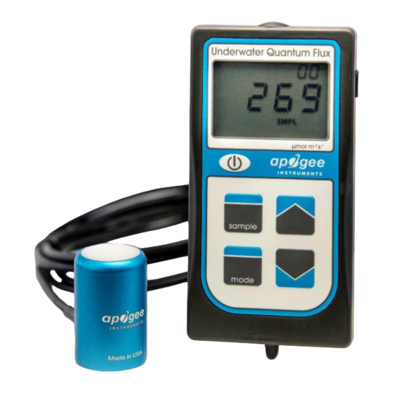
OWNER’S MANUAL UNDERWATER QUANTUM METER Models MQ-510 Rev: 2-Feb-2022 APOGEE INSTRUMENTS, INC. | 721 WEST 1800 NORTH, LOGAN, UTAH 84321, USA TEL: (435) 792-4700 | FAX: (435) 787-8268 | WEB: APOGEEINSTRUMENTS.COM Copyright © 2022 Apogee Instruments, Inc. -
Page 2: Table Of Contents
TABLE OF CONTENTS Owner’s Manual ....................................1 Certificate of Compliance ................................. 3 Introduction ..................................... 4 Sensor Models ..................................5 Specifications ................................... 6 Deployment and Installation ..............................9 Battery Installation and Replacement ............................ 10 Operation and Measurement ..............................11 Apogee AMS Software ................................17 Maintenance and Recalibration ............................. -
Page 3: Certificate Of Compliance
RoHS 3 compliant using exemption 6c. Further note that Apogee Instruments does not specifically run any analysis on our raw materials or end products for the presence of these substances, but we rely on the information provided to us by our material suppliers. -
Page 4: Introduction
The immersion effect correction factor for Apogee full-spectrum quantum sensors (model MQ-500 and SQ-500 series) is 1.25. The MQ-510 quantum meter is designed for underwater measurements, and already applies the immersion effect correction factor to the meter’s readings through firmware. -
Page 5: Sensor Models
SENSOR MODELS Apogee MQ series quantum meters covered in this manual are self-contained and come complete with handheld meter and sensor. A sensor’s model number and serial number are located on a label on the backside of the handheld meter. -
Page 6: Specifications
SPECIFICATIONS MQ-510 Calibration Uncertainty ± 5 % (see calibration Traceability below) Measurement Range 0 to 4000 µmol m Measurement Less than 0.5 % Repeatability Long-term Drift Less than 2 % per year (Non-stability) Non-linearity Less than 1 % (up to 4000 µmol m... - Page 7 Spectral Response Mean spectral response measurements of six replicate Apogee SQ-100X (original X) and MQ-500 (full-spectrum) series quantum sensors. Spectral response measurements were made at 10 nm increments across a wavelength range of 300 to 800 nm with a monochromator and an attached electric light source.
- Page 8 Cosine Response Directional (cosine) response is defined as the measurement error at a specific angle of radiation incidence. Error for Apogee MQ-500 series quantum sensors is approximately ± 2 % and ± 5 % at solar zenith angles of 45° and 75°, respectively. Mean directional (cosine) response of seven apogee MQ-500 series quantum sensors.
-
Page 9: Deployment And Installation
To accurately measure PFFD incident on a horizontal surface, the sensor must be level. The AL-100 accessory leveling plate is recommended for use with the MQ-510 to ensure the sensor is level when attached to a cross-arm. The bubble-level in the plate makes leveling simple and accurate. -
Page 10: Battery Installation And Replacement
BATTERY INSTALLATION AND REPLACEMENT Use a Phillips head screwdriver to remove the screw from the battery cover. Remove the battery cover by slightly lifting and sliding the outer edge of the cover away from the meter. To power the meter, slide the included battery (CR2320) into the battery holder, after removing the battery door from the meter’s back panel. -
Page 11: Operation And Measurement
OPERATION AND MEASUREMENT MQ series quantum meters are designed with a user-friendly interface allowing quick and easy measurements. Press the power button to activate the LCD display. After two minutes of non-activity the meter will revert to sleep mode and the display will shut off to conserve battery life. Press the mode button to access the main menu, where manual or automatic logging are selected, and where the meter can be reset. - Page 12 Reset: To reset the meter, in either SMPL or LOG mode, push the mode button three times (RUN should be blinking), then while pressing the down button, press the mode button once. This will erase all of the saved measurements in memory, but only for the selected mode. That is, performing a reset when in SMPL mode will only erase the manual measurements and performing a reset when in LOG mode will only erase the automatic measurements.
- Page 13 Spectral Error The combination of diffuser transmittance, interference filter transmittance, and photodetector sensitivity yields spectral response of a quantum sensor. A perfect photodetector/filter/diffuser combination would exactly match the defined plant photosynthetic response to photons (equal weighting to all photons between 400 and 700 nm, no weighting of photons outside this range), but this is challenging in practice.
- Page 14 Yield Photon Flux Density (YPFD) Measurements Photosynthesis in plants does not respond equally to all photons. Relative quantum yield (plant photosynthetic efficiency) is dependent on wavelength (green line in figure below) (McCree, 1972a; Inada, 1976). This is due to the combination of spectral absorptivity of plant leaves (absorptivity is higher for blue and red photons than green photons) and absorption by non-photosynthetic pigments.
- Page 15 Correlation between photosynthetic photon flux density (PPFD) and yield photon flux density (YPFD) for multiple different radiation sources. YPFD is approximately 90 % of PPFD. Measurements were made with a spectroradiometer (Apogee Instruments model PS-200) and weighting factors shown in the previous figure were used to calculate PPFD and YPFD.
- Page 16 The MQ-510 sensor has an immersion effect correction factor of 1.25. The immersion effect correction factor is already accounted for in the MQ-510 meter firmware so there is no need to apply the correction factor to your measurements. If you wish to use your meter to make measurements in air, simply divide the measured number by the immersion effect (1.25).
-
Page 17: Apogee Ams Software
APOGEE AMS SOFTWARE Downloading data to a computer requires the AC-100 communication cable and the free ApogeeAMS software. The meter outputs data using the UART protocol and requires the AC-100 to convert from UART to USB, so standard USB cables will not work. The most recent version of ApogeeAMS software can be downloaded at http://www.apogeeinstruments.com/downloads/. - Page 18 “Daily Totals” shows all of the saved Daily Light Integral (DLI) totals per day. Click “30 Min Avg” to see the meter’s 99, 30-minute averages. To analyze the data, click on “File” and “Save As” to save the data as a .csv file. Or, you can highlight the numbers, copy, and paste them into a blank Excel spreadsheet.
-
Page 19: Maintenance And Recalibration
3. Salt deposit accumulation from evaporation of sea spray or sprinkler irrigation water. Apogee Instruments upward-looking sensors have a domed diffuser and housing for improved self-cleaning from rainfall, but active cleaning may be necessary. Dust or organic deposits are best removed using water, or window cleaner, and a soft cloth or cotton swab. - Page 20 Homepage of the Clear Sky Calculator. Two calculators are available: one for quantum sensors (PPFD) and one for pyranometers (total shortwave radiation). Clear Sky Calculator for quantum sensors. Site data are input in blue cells in middle of page and an estimate of PPFD is returned on right-hand side of page.
-
Page 21: Troubleshooting And Customer Support
TROUBLESHOOTING AND CUSTOMER SUPPORT Verify Functionality Pressing the power button should activate the LCD and provide a real-time PPFD reading. Direct the sensor head toward a light source and verify the PPFD reading responds. Increase and decrease the distance from the sensor to the light source to verify that the reading changes proportionally (decreasing PPFD with increasing distance and increasing PPFD with decreasing distance). - Page 22 Error Codes and Fixes Error codes will appear in place of the real-time reading on the LCD display and will continue to flash until the problem is corrected. Contact Apogee if the following fixes do not rectify the problem. Err 1: battery voltage out of range. Fix: replace CR2320 battery and perform master reset. Err 2: sensor voltage out of range.
-
Page 23: Return And Warranty Policy
RETURN AND WARRANTY POLICY RETURN POLICY Apogee Instruments will accept returns within 30 days of purchase as long as the product is in new condition (to be determined by Apogee). Returns are subject to a 10 % restocking fee. WARRANTY POLICY... - Page 24 84321, USA 5. Upon receipt, Apogee Instruments will determine the cause of failure. If the product is found to be defective in terms of operation to the published specifications due to a failure of product materials or craftsmanship, Apogee Instruments will repair or replace the items free of charge.
Need help?
Do you have a question about the MQ-510 and is the answer not in the manual?
Questions and answers