Table of Contents
Advertisement
Quick Links
Advertisement
Table of Contents

Related Manuals for Apogee Instruments MU-250


Summary of Contents for Apogee Instruments MU-250
-
Page 1: Owner's Manual
OWNER’S MANUAL ULTRAVIOLET METER Models MU-250 Rev: 1-Jun-2021 APOGEE INSTRUMENTS, INC. | 721 WEST 1800 NORTH, LOGAN, UTAH 84321, USA TEL: (435) 792-4700 | FAX: (435) 787-8268 | WEB: APOGEEINSTRUMENTS.COM Copyright © 2021 Apogee Instruments, Inc. -
Page 2: Table Of Contents
TABLE OF CONTENTS Owner’s Manual ....................................1 Certificate of Compliance ................................. 3 Introduction ..................................... 4 Sensor Models ..................................5 Specifications ................................... 6 Deployment and Installation ..............................7 Battery Installation and Replacement ............................8 Operation and Measurement ..............................9 Apogee AMS Software ................................11 Maintenance and Recalibration ............................. -
Page 3: Certificate Of Compliance
RoHS 3 compliant using exemption 6c. Further note that Apogee Instruments does not specifically run any analysis on our raw materials or end products for the presence of these substances, but rely on the information provided to us by our material suppliers. -
Page 4: Introduction
Most UV sensors designed for sunlight measurements are sensitive to UV radiation in the UV-A or UV-B ranges. Apogee Instruments MU-200 series UV-A meters detect UV radiation from 300 to 400 nm and are calibrated in energy flux density units of watts per square meter (W m , equal to Joules per second per square meter). -
Page 5: Sensor Models
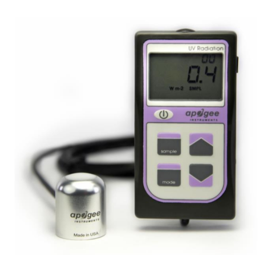
SENSOR MODELS Apogee MU series UV meters covered in this manual are self-contained and come complete with handheld meter and sensor. Sensor model number and serial number are located on a label on the backside of the handheld meter. MU-250... -
Page 6: Specifications
SPECIFICATIONS MU-250 Calibration Uncertainty ± 10 % (see Calibration Traceability below) Measurement Less than 0.5 % Repeatability Non-stability Less than 2 % per year (Long-term Drift) Non-linearity Less than 1 % Response Time Less than 1 ms Field of View 180°... -
Page 7: Deployment And Installation
MU model comes with a different option for mounting the sensor to a horizontal plane. The AL-100 leveling plate is recommended for use with the MU-250. To facilitate mounting to a cross arm, the AL-120 mounting bracket is recommended. -
Page 8: Battery Installation And Replacement
BATTERY INSTALLATION AND REPLACEMENT Use a phillips head screwdriver to remove the screw from the battery cover. Remove the battery cover by slightly lifting and sliding the outer edge of the cover away from the meter. To power the meter, slide the included battery (CR2320) into the battery holder, after removing the battery door from the meter’s back panel. -
Page 9: Operation And Measurement
OPERATION AND MEASUREMENT MU series quantum meters are designed with a user-friendly interface allowing quick and easy measurements. Press the power button to activate the LCD display. After two minutes of non-activity the meter will revert to sleep mode and the display will shut off to conserve battery life. Press the mode button to access the main menu, where the appropriate unit (photon flux or energy flux) and manual or automatic logging are selected, and where the meter can be reset. - Page 10 (http://www.apogeeinstruments.com/ac-100-communcation-cable/). UV-A Measurements and Spectral Errors Apogee Instruments model SU-200 UV-A sensors are calibrated to measure ultraviolet radiation from the sun between 300 and 400 nm in Watts per square meter. In addition to naturally occurring UV-A radiation from the sun, there are many electric light sources that emit UV-A radiation (e.g., cool white fluorescent, metal halide,...
-
Page 11: Apogee Ams Software
APOGEE AMS SOFTWARE Downloading data to a computer requires the AC-100 communication cable and the free ApogeeAMS software. The meter outputs data using the UART protocol and requires the AC-100 to convert from UART to USB, so standard USB cables will not work. The most recent version of ApogeeAMS software can be downloaded at http://www.apogeeinstruments.com/downloads/. - Page 12 “Daily Totals” shows all of the saved Daily Light Integral (DLI) totals per day. Click “30 Min Avg” to see the meter’s 99, 30-minute averages. To analyze the data, click on “File” and “Save As” to save the data as a .csv file. Or, you can highlight the numbers, copy, and paste them into a blank Excel spreadsheet.
-
Page 13: Maintenance And Recalibration
MAINTENANCE AND RECALIBRATION Moisture or debris on the sensor is a common cause of low readings. The sensor has a domed-shaped housing for improved self-cleaning from rainfall, but materials can accumulate on the photo-sensitive area (e.g., dust during periods of low rainfall, salt deposits from evaporation of sea spray or sprinkler irrigation water) and partially block the optical path. -
Page 14: Troubleshooting And Customer Support
TROUBLESHOOTING AND CUSTOMER SUPPORT Verify Functionality Pressing the power button should activate the LCD and provide a real-time UV measurement. Direct the sensor head toward the sun and verify the UV reading responds. Blocking all radiation from the sensor should force the UV reading to zero. - Page 15 Modifying Cable Length Although it is possible to splice additional cable to the separate sensor of the MU-250, note that the cable wires are soldered directly into the circuit board of the meter. Care should be taken to remove the back panel of the meter in order to access the board and splice on the additional cable, otherwise two splices would need to be made between the meter and sensor head.
-
Page 16: Return And Warranty Policy
RETURN AND WARRANTY POLICY RETURN POLICY Apogee Instruments will accept returns within 30 days of purchase as long as the product is in new condition (to be determined by Apogee). Returns are subject to a 10 % restocking fee. WARRANTY POLICY... - Page 17 84321, USA 5. Upon receipt, Apogee Instruments will determine the cause of failure. If the product is found to be defective in terms of operation to the published specifications due to a failure of product materials or craftsmanship, Apogee Instruments will repair or replace the items free of charge.
Need help?
Do you have a question about the MU-250 and is the answer not in the manual?
Questions and answers