Table of Contents
Advertisement
Quick Links
Advertisement
Table of Contents

Subscribe to Our Youtube Channel
Related Manuals for TECHVIEW QV-3147


Summary of Contents for TECHVIEW QV-3147
- Page 1 USER MANUAL...
-
Page 2: Table Of Contents
USER MANUAL Contents CHAPTER 1 FUNCTIONAL DESCRIPTIONS AND FEATURES ......1 CHAPTER 2 OVERVIEW OF DVR ............... 2 2.1 F ....................... 2 RONT ANEL 2.2 Rear Panel ......................3 2.3 R ) ........4 EMOTE ONTROLLER OR REFERENCE ONLY GOODS IN KIND PREVAIL CHAPTER 3 DVR CONNECTION ................ - Page 3 USER MANUAL 6.3.7 System ......................41 6.3.8 Advanced ...................... 43 6.3.9 Local Setting ....................46 6.3.10 Logout......................46 CHAPTER 7 APPENDIX ..................47 7.1 T ....................47 ROUBLESHOOTING 7.2 U ..................48 SAGE AINTENANCE 7.3 S ..................49 YSTEM ONNECTION IAGRAM 7.4 A ) ................
- Page 4 USER MANUAL SAFETY INSTRUCTION Please carefully read the following safety instruction so as to avoid personal injuries and prevent the equipment and other connection devices from being damaged. 1. Power sources (note: please use the power supply attached or specified by the manufacturer) Never operate the equipment by using unspecified power supply.
-
Page 5: Chapter 1 Functional Descriptions And Features
Chapter 1 Functional Descriptions and Features Function Brief Description Support output by monitor, VGA and HDMI, support real-time monitoring by Real time web application manager and mobile phone, and support electronic amplifier, monitoring multi-screen sequence and PIP display. Support video compression standard of H.264. The video quality, resolution of each channel and video frame rate are adjustable. -
Page 6: Chapter 2 Overview Of Dvr
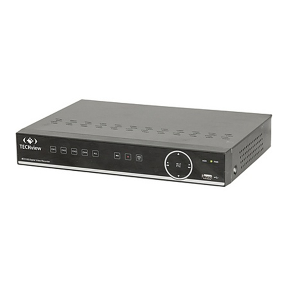
USER MANUAL Chapter 2 Overview of DVR 2.1 Front Panel Key or indicator Identification Functions If the “Green” indicator is on, DVR is getting power Power indicator normally. If the “Red” indicator flashes, the hard drive is being HDD indicator read or written to. -
Page 7: Rear Panel
USER MANUAL 2.2 Rear Panel Physical Interface Connection Audio output Audio signal output, RCA port Video input Connect with CH1-4 (analog) video input device, standard BNC port Audio input Connect with CH1-4 audio input signals, RCA port HDMI Port Connect to HDMI monitor VGA port Connect with VGA display devices, such as PC monitor USB port... -
Page 8: Remote Controller (For Reference Only, Goods In Kind Prevail)
USER MANUAL 2.3 Remote Controller (For reference only, goods in kind prevail) Key function Key title Channel select 1-8; Numeric key Numeric key; Clicking numeric “0” allow 9、0 you switch to output device Multiple display mode Menu Enter into Main menu/Exit Mute Mute on/off SUBMEN... -
Page 9: Power Supply Connection
USER MANUAL 3.3 Power Supply Connection Please use attached power adapter to connect DVR. Before power on, make sure the cables on the audio and video I/O ports and network port are well connected. For audio ports, please use microphone and other audio devices together with BNC connecting line to input or output audio signals. Chapter 4 DVR Boot up 4.1 System Initialization After connecting the power cable of DVR to wall outlet and pressing the power button, you will... -
Page 10: Main Interface
USER MANUAL 2. Record Schedule (Picture 4-4). It can set recording time and scheduled recording of DVR. Picture 4-4 3. HDD Management (Picture 4-5). It supports HDD format and overwrite type. Picture 4-5 4.3 Main Interface Picture 4-6 Note: When internal HDD is not connected to DVR, the character “H” will appear on the lower part of the main interface and accompany buzzer alarm. -
Page 11: Chapter 5 Dvr Menu
USER MANUAL Chapter 5 DVR Menu Popup Menu After finishing system initialization, click right key of mouse on preview interface or slide the mouse to the bottom of screen to enter into Pop-up Menu. Now you could perform parameter setting and operate on Main Menu, Multi-screen, Auto Cruise, Record Search, Sequence, Volume setting and Brightness setting, shown as Picture 5-1. -
Page 12: Main Menu Guide
USER MANUAL 5.1 Main Menu Guide Live Display Output Private Zone Record Record Schedule Mainstream Parameter Network Substream Email Network Email DDNS RTSP Main Menu Motion Alarm Alarm Record Record Event Search Device General Cloud Storage General Users System Info Maintenance Advanced Events... -
Page 13: Main Menu
USER MANUAL 5.2 Main Menu On LIVE mode, click the mouse button, or [Menu] button on the remote controller, or click [ ] icon on the toolbar to enter the main menu screen, as shown in Picture 5-2. If system interface is locked, refer to section 4.3 to unlock by inputting password. - Page 14 USER MANUAL 2. Output Go to “Main Menu”→ “Parameter”→ “Display”→ “Output” to enter into the interface shown as Picture 5-5. Video Output: Live Output Sequence Mode: Set sequence mode SEQ Time: Sequence time is set 5 seconds by default. User may set it as required VGA/HDMI Resolution: For VGA output or HDMI output, the optional resolution include 800×600, 1024×768, 1280×1024, 1440×...
- Page 15 USER MANUAL 5. Record Schedule Go to “Main Menu” → “Parameter” → “Record” → “Record Schedule” to enter into the Record Schedule interface to make record schedule for DVR, as shown in Picture 5-9. Select the channel and the date to be set. One week’s schedule can be set.
- Page 16 USER MANUAL 7. Network Go to “Main Menu” → “Parameter” → “Network” → “Network” to enter the interface shown as Picture 5-11. Select a kind of network connection (PPPOE, DHCP, Static) and set Port, and user may remotely control the monitoring, recording, playback or backup of DVR through network Take DHCP as an example.
- Page 17 USER MANUAL 9. E-mail Go to “Main Menu” → “Parameter” → “Network” → “Email” to enter into the menu interface. Receive or Send DVR alarm Email and set parameters like Email address, SSL, Email Enable, Interval and Email Schedule. The related parameter setting should be consistent with DVR local setting.
- Page 18 USER MANUAL 11. DDNS Go to “Main Menu” → “Parameter” → “Network” → “DDNS” to enter into the menu interface. User may set DDNS in any one of the above 3 network connection types after applying dynamic domain service. User may remotely access DVR through domain by using browser in the form of http://applied domain: mapped Web port number.
- Page 19 USER MANUAL 13. FTP Go to “Main Menu” → “Parameter” → “Network” → “FTP” Set IP, User Name and Password to view the captured pictures in the server (See Picture 5-18). Enter into ftp://relay.anw.ru/and input User Name and Password to view the captured pictures (See Picture 5-19) Picture 5-18 Picture 5-19...
- Page 20 USER MANUAL 15. Alarm Go to “Main Menu” → “Alarm” → “Alarm” to enter into the interface shown as Picture 5-22. It is the alarm management and setting of the machine. User may set alarms under different status in the interface. Please refer to Table 2-4. Alarm In: User may set four groups of alarm input.
-
Page 21: Record Search
USER MANUAL 5.2.2 Record Search 1. General Go to “Main Menu” → “Record Search” → “Record Search” to enter into the interface shown as Picture 5-23. Channel: Select the channel you want to search. Type: Select the type the playback record. There are two options, i.e. - Page 22 USER MANUAL Detailed Operation: Fixed time axis: If you select [ ] option, that means the processing control bar cover two-hour video content. The time range refers to 1 hour before and after the middle point. 2) Record clip and backup function and playback zoom in/out function. Picture 5-27 Picture 5-28 Clip and backup: When it is under single channel playback, the [...
- Page 23 USER MANUAL If you want to back up a record in the detailed file list, you may tick the checkbox at the left of the record (“√”means it has been selected) and click “Backup” to enter into “Select backup type” (Make sure U disk or other portable storage device are connected), as shown in Picture 5-30.
- Page 24 USER MANUAL : Play: Click to play file : Pause: Click to pause. : Stop: Click to stop playback. : Next: Click to play next file. : Previous: Click to play previous file Slow Playing: click to play at 1/2, 1/4, 1/8, 1/16 speed. Fast Playing: click to play at 2×, 4×, 8×, 16×...
-
Page 25: Device
USER MANUAL 5.2.3 Device 1. HDD Go to “Main Menu” → “Device” → “HDD” to enter into the interface shown as Picture 5-35. When HDD is connected, the system will automatically detect if HDD is normal or not; If HDD need to be formatted, status will be shown as “Not formatted”. -
Page 26: Ptz And Cloud Storage
USER MANUAL 5.2.4 PTZ and Cloud Storage 1. PTZ Go to “Main Menu” → “Device” → “PTZ” to enter into the interface shown as Picture 5-37. Select a PTZ channel and set PTZ protocol (Pelco-D, Pelco-P), Baudrate (1200, 2400, 4800, 9600), DataBit (8, 7, 6, 5) , StopBit (1, 2), Parity (None, Odd, Even Mark Space), Address and Cruise. -
Page 27: System
USER MANUAL 6) Click [Active Cloud] to activate Cloud and Email will receive the URL related to Cloud User input the registered user name to visit the above website and the following interface will be popped up. 7) Click the icon at the upper-left to view the folder(CloudDVR000) made in the 4 step . - Page 28 USER MANUAL 3. NTP Go to “Main Menu” → “System” → “General” → “NTP” to enter into the interface shown as Picture 5-42. NTP service: Enable/Disable NTP function. Server Address: Select NTP server (time.windows.com, time.nist.gov, pool.ntp.org). Time Zone: Corresponding time zones for various nations or regions.
- Page 29 USER MANUAL 5. User Edit User may enable or disable the function or set password (See Picture 5-45) Picture 5-45 6. Info Go to “Main Menu” → “System” → “Info” to enter into the interface shown as Picture 5-46. Picture 5-46 7.
-
Page 30: Advanced
USER MANUAL 5.2.6 Advanced 1. Maintain Go to “Main Menu” → “Advanced” → “Maintain” to enter into the interface shown as Picture 5-48. Auto Reboot: Enable the auto maintenance function reboot system regularly every day/week/month. When Auto Reboot is enabled, DVR should be in the main interface and no user operation. -
Page 31: Shutdown
USER MANUAL 5.2.7 Shutdown Go to “Main Menu” → “Shutdown” to enter into the interface shown as Picture 5-50. Picture 5-50 5.3 Menu Lock In consideration of system safety, user may click the icon on the toolbar when he leaves away from DVR and the system interface will be locked. -
Page 32: Mute
USER MANUAL Refer to former section for specific operating method. 5.6 Mute Click icon on the toolbar or Mute button on the panel or remote controller to control the mute of NVR. 5.7 Start Sequence After set channel sequence time, click Start Sequence icon on the toolbar to start sequence. -
Page 33: Web Application Manager Login
USER MANUAL Note: If the ActiveX control is not downloaded successfully, please check if your browser’s safety level or firewall setting is set too high. Please open IE browser → [Menu Bar]Tools → Internet options → Security → Internet → Custom Level → Enable the options (Refer to the Picture 6-1-1 and Picture 6-1-2). -
Page 34: Live Interface
USER MANUAL 6.3 Live Interface Log in and enter into the live interface, as shown in Picture 6-3. Picture 6-3 6.3.1 Menu Bar Menu Bar: Live, Replay, Configuration, Local Setting and Logout. 1. Live Display Log in the Web Application Manager, system will be defaulted to enter into <Live> interface shown as Picture 6-3. -
Page 35: Playback
USER MANUAL : Display previous group of channels : Display next group of channels : Click to maximize the current window to full screen. Right click to pop up menu option and select Exit Full Screen. 2. Video Control Picture 6-5 : Adjust the chromaticity of video : Adjust the brightness of video : Adjust the contrast of video... - Page 36 USER MANUAL 1. Record Search Record playback procedure Firstly, select the date you want to check and tick 1 to 4 channels. Any record files in current channel at current date will be displayed in the status bar of the interface. (See Picture 6-7) Picture 6-7 Secondly, select record type (Normal record, Alarm record and All) and channels, and then click “...
- Page 37 USER MANUAL icon to zoom in/out the time bar display ratio, as shown in Picture 6-8. 2. Playback Control Playback control bar, as shown in picture 6-9. Picture 6-9 Detailed brief description is shown as below list Description Description Play Enable the volume switch Pause Volume adjustment bar...
-
Page 38: Remote Setting
USER MANUAL Record file download Click download icon “ ” on the control bar to display all the matched record file according to the search conditions of channels, as shown in picture 6-11. Picture 6-11 Tick-select the record file you want to download and click [Start download] .System will download the record file in sequence and save to local PC. - Page 39 USER MANUAL 1. Display Unfold [Display] option to find its sub-options: Live and Privacy zone. 1) Live: You may change channel name, position, channel preview and relevant parameters. If show time is set as <disable>, current DVR system time will not appear on the screen on Live mode.
-
Page 40: Network
USER MANUAL 2) Record Schedule. The parameters should be consistent with DVR local setting, as shown in Picture 6-16. Picture 6-16 Green stands for Normal record; Yellow stands for Motion detection; Red stands for I/O trigger record. 3) Mainstream: User may set Mainstream, as shown in Picture 6-17. The relevant parameters should be consistent with DVR local setting. - Page 41 USER MANUAL 2. Substream User may set Mainstream, as shown in Picture 6-19. The relevant parameters should be consistent with DVR local setting. Picture 6-19 3. Email Email: Set DVR alarm Email configuration parameters, including Email address, SSL, Email Enable, Interval and Email Schedule, etc. Detailed parameters should be consistent with DVR local setting.
- Page 42 USER MANUAL 4. DDNS DDNS: After user applies for DDNS service, you could enable <DDNS> function under any one network type mode (Static, DHCP and PPPoE). And you may remotely visit the NVR through domain name (http://domain name: Web port No.). When visiting DVR by using DDNS, user should make sure port and current IP can be normally connected in public network.
-
Page 43: Alarm
USER MANUAL 6.3.5 Alarm Alarm setting includes Motion Detection and I/O Alarm Parameters. 1. Motion Detection Configure Sensitivity, Alarm out, Alarm Record and Alarm Capture, etc. Detailed setting should be consistent with DVR local setting (See Picture 6-24). Picture 6-24 2. -
Page 44: Device
USER MANUAL 6.3.6 Device Click <Device> to unfold its sub-options: HDD and PTZ 1. HDD User may check HDD status of DVR and overwritten time. Detail setting should be consistent with DVR local setting. Please refer to Picture 6-26. Picture 6-26 2. -
Page 45: System
USER MANUAL 3. Cloud Storage User may set the relevant parameters of Cloud Storage. Detail setting should be consistent with DVR local setting. Please refer to Picture 6-28-1 and 6-28-2. Picture 6-28-1 Picture 6-28-2 6.3.7 System Click <System> option to unfold its sub-options: General, Users and Information. 1. - Page 46 USER MANUAL 2. Users User may configure user name and password and detailed setting should be consistent with DVR local setting. Please refer to Picture 6-30. Picture 6-30 3. Information User may search device name, device number, device type, MAC address, software version, IE version and hardware version of DVR shown as Picture 6-31.
-
Page 47: Advanced
USER MANUAL 6.3.8 Advanced Click Advance to unfold its sub-options: Firmware Update, Load default, Events and Maintain. 1. Firmware Update User may remotely update DVR system, as shown in Picture 6-32. Picture 6-32 Updating procedure: Firstly, select the update file path. The file format is .sw. Please refer to Picture 6-33. Picture 6-33 Secondly, click “Start”... - Page 48 USER MANUAL 3. Events User may configure Event Type, Buzzer, Send Email, Show Message and other parameters shown as Picture 6-35. Detailed setting should be consistent with DVR local setting. Picture 6-35 4. Maintain Allow you remotely set auto maintain time for DVR shown as Picture 6-36. Detailed setting should be consistent with DVR local setting.
- Page 49 USER MANUAL 6. AVD Exception Detection Totally 8 kinds of detection items: Brightness detection, Definition, Noise, Freeze, Signal loss, Scene change, Artificial disturbance, PTZ lose control. Detailed setting should be consistent with DVR local setting. Refer to Picture 6-38. Picture 6-38 7.
-
Page 50: Local Setting
USER MANUAL 6.3.9 Local Setting User may set Record Path (save Live record and Playback clip file), Download Path for remote file, Snapshot Path for captured pictures, Interval for switching record files (Packaging time), and File type (H264 and AVI) shown as Picture 6-40. Picture 6-40 6.3.10 Logout Click... -
Page 51: Chapter 7 Appendix
USER MANUAL Chapter 7 Appendix 7.1 Troubleshooting Q: What can I do if the system does not detect the HDD? A: Check if the power supply system is properly connected and data cord and power cables are securely connected, and if something wrong with the HDD interface. Or you may check if your HDD is supported by referring to the specifications or descriptions. -
Page 52: Usage Maintenance
USER MANUAL Q: Why doesn’t dynamic detection work? A: Please check if the motion detection time and motion detection regional setting are correct and if the sensitivity is set too low. Q: Why doesn’t alarm work? A: Please check if the alarm setting, alarm connection and alarm input signals are correct. Q: Why does buzzer keep alarming? A: Please check the alarm setting, check if motion detection function is enabled and object motion is detected all the time and if I/O alarm is set as Always Off. -
Page 53: System Connection Diagram
USER MANUAL 7.3 System Connection Diagram 7.4 Accessories (Goods in kind prevail) Remote Conroller Power Adapter User Mannual (Good in kind prevail) USB mouse Warranty Card... - Page 54 USER MANUAL The material in this document is the intellectual property of our department . No part of this manual reproduced, copied, translated, transmitted, or published in any form or by any means without our department prior written permission. Our products are under continual improvement and we reserve the right to make changes without notice.
Need help?
Do you have a question about the QV-3147 and is the answer not in the manual?
Questions and answers