Table of Contents
Advertisement
GA-8I945GZME-RH
Intel
Pentium
®
®
User's Manual
Rev. 1003
12ME-945GZMER-1003R
* The WEEE marking on the product indicates this product must not be disposed of with user's other household waste
and must be handed over to a designated collection point for the recycling of waste electrical and electronic equipment!!
* The WEEE marking applies only in European Union's member states.
4 LGA775 Processor Motherboard
Advertisement
Table of Contents

Related Manuals for Gigabyte GA-8I945GZME-RH


Summary of Contents for Gigabyte GA-8I945GZME-RH
- Page 1 GA-8I945GZME-RH Intel Pentium 4 LGA775 Processor Motherboard ® ® User's Manual Rev. 1003 12ME-945GZMER-1003R * The WEEE marking on the product indicates this product must not be disposed of with user's other household waste and must be handed over to a designated collection point for the recycling of waste electrical and electronic equipment!!
- Page 3 Gigabyte's prior written permission. Specifications and features are subject to change without prior notice. Product Manual Classification In order to assist in the use of this product, Gigabyte has categorized the user manual in the following: For detailed product information and specifications, please carefully read the "User’s Manual."...
-
Page 4: Table Of Contents
Table of Contents Item Checklist ... 6 Optional Accessories ... 6 GA-8I945GZME-RH Motherboard Layout ... 7 Block Diagram ... 8 Chapter 1 Hardware Installation ... 9 Considerations Prior to Installation ... 9 Feature Summary ... 10 Installation of the CPU and CPU Cooler ... 12 1-3-1 Installation of the CPU ... - Page 5 Chapter 3 Install Drivers ... 49 Install Chipset Drivers ... 49 Software Applications ... 50 Driver CD Information ... 50 Hardware Information ... 51 Contact Us ... 51 Chapter 4 Appendix ... 53 Unique Software Utilities ... 53 4-1-1 EasyTune 5 Introduction ... 53 4-1-2 Xpress Recovery2 Introduction ...
-
Page 6: Item Checklist
Item Checklist IDE Cable x 1, FDD Cable x 1 SATA 3Gb/s Cable x 1 I/O Shield * The items listed above are for reference only, and are subject to change without notice. Optional Accessories 2 Ports USB2.0 Cable (Part Number: 12CR1-1UB030-51/R) COM Port Cable (Part Number: 12CF1-1CM001-31/R) 5.1/7.1 Surround Cable (Part Number: 12CF1-1AU004-01R ) - 6 -... -
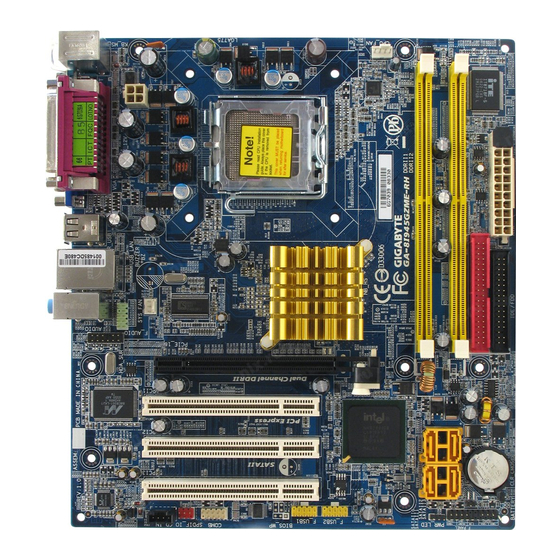
Page 7: Ga-8I945Gzme-Rh Motherboard Layout
GA-8I945GZME-RH Motherboard Layout KB_MS ATX_12V R_USB USB_LAN AUDIO SYS _FAN F_AUDIO HDA_SUR CODEC CD_IN SPDIF_IO CPU_FAN LGA775 Intel 945GZ PCI1 PCI2 PCI3 BIOS COMB F_USB1 F_USB2 - 7 - PCIE_16 SATAII2 SATAII3 ICH7 SATAII0 CLR_CMOS SATAII1 F_PANEL PWR_LED... -
Page 8: Block Diagram
Block Diagram LGA775 Processor Host Interface DDRII 533MHz DIMM Dual Channel Memory PCI-ECLK Intel (100MHz) 945GZ GMCH PCI Express x4 BIOS 4 Serial ATA Intel PCI Bus ICH7 ATA33/66/100 IDE Channel Marvell 8001 Floppy RJ45 LPT Port IT8718 CODEC COM Ports 8 USB PS/2 KB/Mouse Ports... -
Page 9: Chapter 1 Hardware Installation
2. Damage as a result of violating the conditions recommended in the user manual. 3. Damage due to improper installation. 4. Damage due to use of uncertified components. 5. Damage due to use exceeding the permitted parameters. 6. Product determined to be an unofficial Gigabyte product. - 9 - Hardware Installation... -
Page 10: Feature Summary
1 CD In connector 1 COMB connector 1 power LED connector 2 USB 2.0/1.1 connectors for additional 4 USB 2.0/1.1 ports by cables 1 SPDIF In/Out connector 1 HDA_SUR connector GA-8I945GZME-RH Motherboard Pentium 4 Processor ® ® (Note 1) ®... - Page 11 Micro ATX form factor; 24.4cm x 22.0cm (Note 1) For further CPU support information, please go to GIGABYTE's website. (Note 2) The GA-8I945GZME-RH supports up to PCI Express x4 mode. (please refer to the VGA cards support list on page 16) (Note 3) EasyTune functions may vary depending on different motherboards.
-
Page 12: Installation Of The Cpu And Cpu Cooler
Avoid twisting or bending motions that might cause damage to the CPU during installation.) GA-8I945GZME-RH Motherboard Fig. 2 Remove the plastic covering on the CPU socket. -
Page 13: Installation Of The Heatsink
1-3-2 Installation of the Heatsink Fig.1 Please apply an even layer of heatsink paste on the surface of the installed CPU. Fig. 3 Place the heatsink atop the CPU and make sure the push pins aim to the pin hole on the motherboard.Pressing down the push pins diagonally. -
Page 14: Installation Of Memory
Memory modules are designed so that they can be inserted only in one direction. The memory capacity used can differ with each slot. GA-8I945GZME-RH Motherboard Fig.1 The DIMM socket has a notch, so the DIMM memory mod- ule can only fit in one direction. -
Page 15: Installation Of Expansion Cards
Dual Channel Memory Configuration The GA-8I945GZME-RH supports the Dual Channel Technology. After oper- ating the Dual Channel Technology, the bandwidth of Memory Bus will double. Due to CPU limitation, if you wish to operate the Dual Channel Technology, follow the guidelines below: 1. -
Page 16: Graphics Card Support List
WinFast Gigabyte Gigabyte Gigabyte Gigabyte Gigabyte Gigabyte Gigabyte Gigabyte Gigabyte Gigabyte Gigabyte Gigabyte Gigabyte Gigabyte Gigabyte Gigabyte ASUS ASUS GA-8I945GZME-RH Motherboard Model Name GV-NX53128D GV-NX57128D GV-NX59128D GV-NX62128D GV-NX66256D GV-NX66T128VP GV-NX66T128D GV-NX68T256DH GV-NX55128DP GV-NX68U256D GV-NX62TC256D GV-NX62TC128D GV-NX66L128DP GV-NX68256D GV-NX78X256V-B GV-NX78T256V-B GV-NX79T256DP-RH... -
Page 17: I/O Back Panel Introduction
I/O Back Panel Introduction PS/2 Keyboard and PS/2 Mouse Connector To install a PS/2 port keyboard and mouse, plug the mouse to the upper port (green) and the keyboard to the lower port (purple). Parallel Port The parallel port allows connection of a printer, scanner and other peripheral devices. Serial Port (COMA) Devices like mouses, modems, and etc. -
Page 18: Connectors Introduction
Connectors Introduction ATX_12V ATX (Power Connector) CPU_FAN SYS_FAN SATAII0 / SATAII1 /S ATAII2 / SATAII3 PWR_LED F_AUDIO GA-8I945GZME-RH Motherboard F_PANEL CD_IN SPDIF_IO HDA_SUR F_USB1 / F_USB2 COMB CLR_CMOS - 18 -... - Page 19 1/2) ATX_12V/ATX (Power Connector) With the use of the power connector, the power supply can supply enough stable power to all the components on the motherboard. Before connecting the power connector, please make sure that all components and devices are properly installed. Align the power connector with its proper location on the motherboard and connect tightly.
- Page 20 Slave (for information on settings, please refer to the instructions located on the IDE device). Before attaching the IDE cable, please take note of the foolproof groove in the IDE connector. GA-8I945GZME-RH Motherboard Pin No. Definition...
- Page 21 6) FDD (FDD Connector) The FDD connector is used to connect the FDD cable while the other end of the cable connects to the FDD drive. The types of FDD drives supported are: 360KB, 720KB, 1.2MB, 1.44MB and 2.88MB. Before attaching the FDD cable, please take note of the foolproof groove in the FDD connector.
-
Page 22: Front Audio Connector
By default, the audio driver is configured to support HD Audio. To connect an AC97 front panel audio module to this connector, please refer to the instructions on Page 65 about the software settings. GA-8I945GZME-RH Motherboard Pin No. Definition MPD+... - Page 23 10) F_PANEL (Front Panel Jumper) Please connect the power LED, PC speaker, reset switch and power switch etc of your chassis front panel to the F_PANEL connector according to the pin assignment below. HD (IDE Hard Disk Active LED) SPEAK (Speaker Connector) RES (Reset Switch) PW (Power Switch) MSG (Message LED/Power/Sleep LED)
- Page 24 Be careful with the polarity of the SPDIF_IO connector. Check the pin assignment carefully while you connect the SPDIF cable, incorrect connection between the cable and connector will make the device unable to work or even damage it. For optional SPDIF cable, please contact your local dealer. GA-8I945GZME-RH Motherboard Pin No. Definition CD-L CD-R Pin No.
- Page 25 13) HDA_SUR (Surround Center Connector) Please connect the connector of the Surround Kit module to this connector. 14) F_USB1/F_USB2 (Front USB Connectors) Be careful with the polarity of the front USB connector. Check the pin assignment carefully while you connect the front USB cable, incorrect connection between the cable and connector will make the device unable to work or even damage it.
- Page 26 COMB cable. Please contact your nearest dealer for optional COMB cable. 16) CI (Chassis Intrusion, Case Open) This 2-pin connector allows your system to detect if the chassis cover is removed. You can check the "Case Opened" status in BIOS Setup. GA-8I945GZME-RH Motherboard Pin No. Definition NDCDB-...
- Page 27 17) CLR_CMOS (Clear CMOS) You may clear the CMOS data to its default values by this header. To clear CMOS, temporarily short the two pins. Default doesn't include the jumper to avoid improper use of this header. 18) BATTERY Open: Normal Short: Clear CMOS Danger of explosion if battery is incorrectly replaced.
- Page 28 GA-8I945GZME-RH Motherboard - 28 -...
-
Page 29: Chapter 2 Bios Setup
CMOS SETUP screen. You can enter the BIOS setup screen by pressing "Ctrl + F1". If you wish to upgrade to a new BIOS, either GIGABYTE's Q-Flash or @BIOS utility can be used. Q-Flash allows the user to quickly and easily update or backup BIOS without entering the operating system. -
Page 30: The Main Menu (For Example: Bios Ver. : E7)
This action makes the system reset to the default for stability. The BIOS Setup menus described in this chapter are for reference only and may differ from the exact settings for your motherboard. GA-8I945GZME-RH Motherboard <F12> For Boot Menu Boot Menu... - Page 31 Standard CMOS Features This setup page includes all the items in standard compatible BIOS. Advanced BIOS Features This setup page includes all the items of Award special enhanced features. Integrated Peripherals This setup page includes all onboard peripherals. Power Management Setup This setup page includes all the items of Green function features.
-
Page 32: Standard Cmos Features
Select this if no IDE devices are used and the system will skip the automatic detection step and allow for faster system start up. Access Mode Use this to set the access mode for the hard drive. The two options are: Large/Auto(default:Auto) GA-8I945GZME-RH Motherboard Standard CMOS Features Wed, Apr 12 2006 14:31:24... - Page 33 Capacity Capacity of currently installed hard drive. Hard drive information should be labeled on the outside drive casing. Enter the appropriate option based on this information. Cylinder Number of cylinders Head Number of heads Precomp Write precomp Landing Zone Landing zone Sector Number of sectors Drive A...
-
Page 34: Advanced Bios Features
The system will boot, but access to Setup will be denied if the correct password is not entered at the prompt. (Default value) (Note) This item will show up when you install a processor which supports this function. GA-8I945GZME-RH Motherboard Advanced BIOS Features [Press Enter]... - Page 35 CPU Hyper-Threading Enabled Enables CPU Hyper Threading Feature. Please note that this feature is only working for operating system with multi processors mode supported. (Default value) Disabled Disables CPU Hyper Threading. Limit CPUID Max. to 3 Enabled Limit CPUID Maximum value to 3 when use older OS like NT4. Disabled Disables CPUID Limit for windows XP.
-
Page 36: Integrated Peripherals
If PATA IDE were set to Ch. 0 Master/Slave,this function will auto set to Ch. 1 Master/Slave. USB Controller Enabled Enable USB controller. (Default value) Disabled Disable USB controller. GA-8I945GZME-RH Motherboard Integrated Peripherals [Enabled] [Auto] Ch.0 Master/Slave Ch.2 Master/Slave Ch.3 Master/Slave... - Page 37 USB 2.0 Controller You can disable this function if you are not using onboard USB 2.0 feature. Enabled Enable USB 2.0 controller. (Default value) Disabled Disable USB 2.0 controller. USB Keyboard Support Enabled Enable USB keyboard support. Disabled Disable USB keyboard support. (Default value) USB Mouse Support Enabled Enable USB mouse support.
- Page 38 Using Parallel port as Extended Capabilities Port. ECP+EPP Using Parallel port as ECP & EPP mode. ECP Mode Use DMA Set ECP Mode Use DMA to 3. (Default value) Set ECP Mode Use DMA to 1. GA-8I945GZME-RH Motherboard - 38 -...
-
Page 39: Power Management Setup
Power Management Setup CMOS Setup Utility-Copyright (C) 1984-2006 Award Software ACPI Suspend Type Soft-Off by PWR-BTTN PME Event Wake Up Power On by Ring Resume by Alarm x Date (of Month) Alarm x Time (hh:mm:ss) Alarm Power On By Mouse Power On By Keyboard x KB Power ON Password AC Back Function... - Page 40 When AC-power back to the system, the system will be in "Off" state. (Default value) Full-On When AC-power back to the system, the system always in "On" state. Memory When AC-power back to the system, the system will return to the Last state before AC-power off. GA-8I945GZME-RH Motherboard - 40 -...
-
Page 41: Pnp/Pci Configurations
PnP/PCI Configurations CMOS Setup Utility-Copyright (C) 1984-2006 Award Software PCI 1 IRQ Assignment PCI 2 IRQ Assignment PCI 3 IRQ Assignment : Move Enter: Select F5: Previous Values PCI 1 IRQ Assignment Auto 3,4,5,7,9,10,11,12,14,15 PCI 2 IRQ Assignment Auto 3,4,5,7,9,10,11,12,14,15 PCI 3 IRQ Assignment Auto 3,4,5,7,9,10,11,12,14,15... -
Page 42: Pc Health Status
Monitor CPU temperature at 90 Disabled Disable this function. (Default value) CPU/System FAN Fail Warning Disabled Disable fan warning function. (Default value) Enabled Enable fan warning function. GA-8I945GZME-RH Motherboard PC Health Status [Disabled] 2880 RPM [Disabled] [Disabled] [Disabled] [Enabled] [Auto]... - Page 43 CPU Smart FAN Control Disabled Disable this function. Enabled When this function is enabled, CPU fan will run at different speed depending on CPU temperature. Users can adjust the fan speed with Easy Tune based on their requirements. (Default value) CPU Smart FAN Mode This option is available only when CPU Smart FAN Control is enabled.
-
Page 44: Frequency/Voltage Control
Set Memory frequency by DRAM SPD data. (Default value) Memory Frequency (Mhz) The values depend on "System Memory Multiplier" item. (Note) This item will show up when you install a processor which supports this function. GA-8I945GZME-RH Motherboard Frequency/Voltage Control [18X] [Auto]... -
Page 45: Load Fail-Safe Defaults
Load Fail-Safe Defaults CMOS Setup Utility-Copyright (C) 1984-2006 Award Software Standard CMOS Features Advanced BIOS Features Integrated Peripherals Power Management Setup PnP/PCI Configurations PC Health Status Frequency/Voltage Control ESC: Quit F8: Q-Flash Fail-Safe defaults contain the most appropriate values of the system parameters that allow minimum system performance. -
Page 46: Set Supervisor/User Password
Setup Menu. If you select "Setup" at "Password Check" in Advance BIOS Features Menu, you will be prompted only when you try to enter Setup. GA-8I945GZME-RH Motherboard Load Fail-Safe Defaults Load Optimized Defaults... -
Page 47: Save & Exit Setup
2-11 Save & Exit Setup CMOS Setup Utility-Copyright (C) 1984-2006 Award Software Standard CMOS Features Advanced BIOS Features Integrated Peripherals Power Management Setup PnP/PCI Configurations PC Health Status Frequency/Voltage Control ESC: Quit F8: Q-Flash Type "Y" will quit the Setup Utility and save the user setup value to RTC CMOS. Type "N"... - Page 48 GA-8I945GZME-RH Motherboard - 48 -...
-
Page 49: Chapter 3 Install Drivers
Chapter 3 Install Drivers Pictures below are shown in Windows XP. Insert the driver CD-title that came with your motherboard into your CD-ROM drive, the driver CD-title will auto start and show the installation guide. If not, please double click the CD-ROM device icon in "My computer", and execute the Run.exe. -
Page 50: Software Applications
Software Applications This page displays all the tools that Gigabyte developed and some free software, you can choose anyone you want and press "install" to install them. Driver CD Information This page lists the contents of software and drivers in this CD-title. -
Page 51: Hardware Information
Hardware Information This page lists all device you have for this motherboard. Contact Us Please see the last page for details. - 51 - Install Drivers... - Page 52 GA-8I945GZME-RH Motherboard - 52 -...
-
Page 53: Chapter 4 Appendix
Enters the PC Health setting page Confirmation and Execution button Toggles between Easy and Advance Mode Display panel of CPU frequency Shows the current functions status Log on to GIGABYTE website Display EasyTune 5 Help file Quit or Minimize EasyTune 5 software... -
Page 54: Xpress Recovery2 Introduction
3. It is recommended that Xpress Recovery2 be immediately installed once you com- plete installations of OS and all required drivers as well as software. GA-8I945GZME-RH Motherboard Boot from CD/DVD: <F9> Xpress Recovery2 - 54 -... - Page 55 2. It is normal that data backup takes longer time than data restoration. 3. Xpress Recovery2 is compliant with the GPL regulations. 4. On a few motherboards based on Nvidia chipsets, BIOS update is required for Xpress Recovery2 to correctly identify RAID and SATA IDE mode. Please contact your motherboard manufacturer.
-
Page 56: Flash Bios Method Introduction
Updating BIOS with Q-Flash Utility on Dual BIOS Motherboards. Some of Gigabyte motherboards are equipped with dual BIOS. In the BIOS menu of the motherboards supporting Q-Flash and Dual BIOS, the Q-Flash utility and Dual BIOS utility are combined in the same screen. - Page 57 Entering the Q-Flash utility: Step1: To use Q-Flash utility, you must press Del in the boot screen to enter BIOS menu. CMOS Setup Utility-Copyright (C) 1984-2004 Award Software Standard CMOS Features Advanced BIOS Features Integrated Peripherals Power Management Setup PnP/PCI Configurations PC Health Status MB Intelligent Tweaker(M.I.T.) ESC: Quit...
- Page 58 Copy Main ROM Data to Backup Don't Turn Off Power or Reset System Enter : Run After BIOS file is read, you'll see a confirmation dialog box asking you "Are you sure to update BIOS?" GA-8I945GZME-RH Motherboard Dual BIOS Utility Main Bios Disable...
- Page 59 3. Press Y button on your keyboard after you are sure to update BIOS. Then it will begin to update BIOS. The progress of updating BIOS will be displayed. Please do not take out the floppy disk when it begins flashing BIOS. 4.
-
Page 60: Updating Bios With Q-Flash Utility On Single-Bios Motherboards
Press Y on your keyboard to save and exit. Part Two: Updating BIOS with Q-Flash Utility on Single-BIOS Motherboards. This part guides users of single-BIOS motherboards how to update BIOS using the Q-Flash CMOS Setup Utility-Copyright (C) 1984-2004 Award Software Standard CMOS Features Advanced BIOS Features... - Page 61 Exploring the Q-Flash utility screen The Q-FlashBIOS utility screen consists of the following key components. Flash Type/Size...SST 49LF003A Task menu for Q-Flash utility Enter : Run Task menu for Q-Flash utility: Contains the names of three tasks. Blocking a task and pressing Enter key on your keyboard to enable execution of the task.
- Page 62 Press Del to enter BIOS menu after system reboots and "Load BIOS Fail-Safe Defaults". See how to Load BIOS Fail-Safe Defaults, please kindly refer to Step 6 to 7 in Part One. Congratulation!! You have updated BIOS successfully!! GA-8I945GZME-RH Motherboard Q-Flash Utility V1.30 Keep DMI Data...
- Page 63 Please search for BIOS unzip file, downloading from internet or any other methods (such as: 8I945GZME-RH.F1). Complete update process following the instruction. Utility Fig 2. Installation Complete and Run @BIOS Click Sart/ Programs/ GIGABYTE/@BIOS Fig 4. Select the desired @BIOS server - 63 - Appendix...
- Page 64 Otherwise, your system won't boot. III. In method I, if the BIOS file you need cannot be found in @BIOS Gigabyte's web site for downloading and updating it according to method II. IV. Please note that any interruption during updating will cause system unbooted.
-
Page 65: 4- / 6- / 8- Channel Audio Introduction
Installing the 5.1/7.1 Surround Cable (Optional) The 5.1/7.1 Surround Cable provides center/ subwoofer speaker out, rear speaker out, and side speaker out audio jacks. To set up multi-channel surround sound, this cable needs to be installed. Step: 1. Connect the 5.1/7.1 surround cable connector to the HDA_SUR header on the motherboard. - Page 66 Out jack, a small window will pop up and ask you what type of equipment is connected. Choose Headphone or Line Out depending on the device connected and click OK. The 2-channel audio setup is completed. GA-8I945GZME-RH Motherboard - 66 -...
- Page 67 Setting Up 4-Channel Audio STEP 1 : After installation of the audio driver, you should find an Audio Manager icon in your system tray (you can also find the icon in Control Panel). Double- click the icon to open the Audio Control Panel. STEP 2: In the Audio Control Panel, click the Audio I/O tab.
- Page 68 Choose a device depend- ing on the type of speaker connected (6-channel audio consists of Front Speaker Out (Line Out), Rear Speaker Out, and Center/Subwoofer Speaker Out) then click OK. The 6-channel audio setup is completed. GA-8I945GZME-RH Motherboard - 68 -...
- Page 69 Setting Up 8-Channel Audio STEP 1 : After installation of the audio driver, you should find an Audio Manager icon in your system tray (you can also find the icon in Control Panel). Double- click the icon to open the Audio Control Panel. STEP 2: In the Audio Control Panel, click the Audio I/O tab.
- Page 70 AC97 Audio mode, go to the Audio Control Panel and click the Audio I/O tab. In the ANA- LOG area, click the Tool icon and then select the Disable front panel jack detection check box. This action completes the AC'97 Audio configuration. GA-8I945GZME-RH Motherboard - 70 -...
-
Page 71: Troubleshooting
Below is a collection of general asked questions. To check general asked questions based on a specific motherboard model, please log on to http://www.gigabyte.com.tw Question 1: I cannot see some options that were included in previous BIOS after updating BIOS. Why? Answer: Some advanced options are hidden in new BIOS version. - Page 72 GA-8I945GZME-RH Motherboard - 72 -...
- Page 73 - 73 - Appendix...
- Page 74 GA-8I945GZME-RH Motherboard - 74 -...
- Page 75 - 75 - Appendix...
- Page 76 GA-8I945GZME-RH Motherboard - 76 -...
- Page 77 - 77 - Appendix...
- Page 78 GA-8I945GZME-RH Motherboard - 78 -...
- Page 79 GIGA-BYTE TECHNOLOGY CO., LTD. Address: No.6, Bau Chiang Road, Hsin-Tien, Taipei 231, Taiwan TEL: +886-2-8912-4888 FAX: +886-2-8912-4003 Tech. and Non-Tech. Support (Sales/Marketing) : http://ggts.gigabyte.com.tw WEB address (English): http://www.gigabyte.com.tw WEB address (Chinese): http://www.gigabyte.tw U.S.A. G.B.T. INC. TEL: +1-626-854-9338 FAX: +1-626-854-9339 Tech. Support: http://rma.gigabyte-usa.com...
- Page 80 Germany G.B.T. TECHNOLOGY TRADING GMBH WEB address : http://www.gigabyte.de U.K. G.B.T. TECH. CO., LTD. WEB address : http://www.giga-byte.co.uk The Netherlands GIGA-BYTE TECHNOLOGY B.V. WEB address : http://www.giga-byte.nl France GIGABYTE TECHNOLOGY FRANCE WEB address : http://www.gigabyte.fr Italy WEB address : http://www.giga-byte.it...
Need help?
Do you have a question about the GA-8I945GZME-RH and is the answer not in the manual?
Questions and answers