Gigabyte GA-8I915P Duo User Manual
Intel pentium 4 lga775 processor motherboard
Hide thumbs
Also See for GA-8I915P Duo:
- User manual (88 pages) ,
- User manual (80 pages) ,
- User manual (88 pages)

Related Manuals for Gigabyte GA-8I915P Duo


Summary of Contents for Gigabyte GA-8I915P Duo
- Page 1 GA-8I915P Duo Intel Pentium 4 LGA775 Processor Motherboard ® ® User's Manual Rev. 2001 12ME-8I915PD2-2001...
- Page 3 Gigabyte's prior written permission. Specifications and features are subject to change without prior notice. Product Manual Classification In order to assist in the use of this product, Gigabyte has categorized the user manual in the following: For quick installation, please refer to the "Hardware Installation Guide" included with the product.
-
Page 4: Table Of Contents
Table of Contents GA-8I915P Duo Motherboard Layout ... 6 Block Diagram ... 7 Chapter 1 Hardware Installation ... 9 Considerations Prior to Installation ... 9 Feature Summary ... 10 Installation of the CPU and Heatsink ... 12 1-3-1 Installation of the CPU ... 12 1-3-2 Installation of the Heatsink ... - Page 5 Chapter 3 Install Drivers ... 49 Install Chipset Drivers ... 49 Software Applications ... 50 Driver CD Information ... 50 Hardware Information ... 51 Contact Us ... 51 Chapter 4 Appendix ... 53 Unique Software Utilities ... 53 4-1-1 EasyTune 5 Introduction ... 54 4-1-2 Xpress Recovery Introduction ...
-
Page 6: Ga-8I915P Duo Motherboard Layout
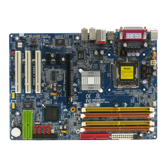
GA-8I915P Duo Motherboard Layout ATX_12V KB_MS R_USB AUDIO1 AUDIO2 IT8712 F_AUDIO Marvell 8001 CODEC CD_IN BIOS SPDIF_IO CPU_FAN LGA775 Intel 915P PCIE_16 PCIE_1 PCIE_2 PCI1 PCI2 PCI3 F_USB2 F_USB1 - 6 - IDE1 SYS_FAN ICH6 SATA3 SATA2 SATA1 SATA0 VT6410... -
Page 7: Block Diagram
Block Diagram PCI-ECLK (100MHz) PCI Express x16 2 PCI Express x1 PCI-ECLK (100MHz) PCI Express Bus PCI Bus Marvell VT6410 8001 IDE RAID RJ45 IDE2/IDE3 3 PCI PCICLK (33MHz) (Note) To use a DDRII 600 memory module on the motherboard, you must install an 800MHz FSB processor and overclock in BIOS. - Page 8 - 8 -...
-
Page 9: Chapter 1 Hardware Installation
2. Damage as a result of violating the conditions recommended in the user manual. 3. Damage due to improper installation. 4. Damage due to use of uncertified components. 5. Damage due to use exceeding the permitted parameters. 6. Product determined to be an unofficial Gigabyte product. - 9 - Hardware Installation... -
Page 10: Feature Summary
Onboard Marvell 8001 chip (10/100/1000 Mbit) 1 RJ 45 port (Note) To use a DDRII 600 memory module on the motherboard, you must install an 800MHz FSB processor and overclock in BIOS. GA-8I915P Duo Motherboard Pentium 4 LGA775 CPU ®... - Page 11 Onboard Audio ALC850 CODEC (UAJ) Supports Jack Sensing function Supports 2 / 4 / 6 / 8 channel audio Supports Line In ; Line Out (Front Speaker Out) ; MIC ; Surround Speaker Out (Rear Speaker Out) ; Center/Subwoofer Speaker Out ; Side Speaker Out connection Supports SPDIF In/Out connection CD In...
-
Page 12: Installation Of The Cpu And Heatsink
Avoid twisting or bending motions that might cause damage to the CPU during installation.) GA-8I915P Duo Motherboard Fig. 2 Remove the plastic covering on the CPU socket. -
Page 13: Installation Of The Heatsink
1-3-2 Installation of the Heatsink Fig.1 Please apply an even layer of heatsink paste on the surface of the installed CPU. Fig. 3 Place the heatsink atop the CPU and make sure the push pins aim to the pin hole on the motherboard.Pressing down the push pins diagonally. -
Page 14: Installation Of Memory
The motherboard supports DDR/DDRII memory modules, whereby BIOS will automatically detect memory capacity and specifications. Memory modules are designed so that they can be inserted only in one direction. The memory capacity used can differ with each slot. GA-8I915P Duo Motherboard Notch DDR II Fig.1... - Page 15 GA-8I915P Duo supports the Dual Channel Technology. After operating the Dual Channel Technology, the bandwidth of Memory Bus will add double. GA-8I915P Duo includes 4 DIMM sockets, and each Channel has two DIMM sockets as following: Channel A : DDR 1...
-
Page 16: Installation Of Expansion Cards
Power on the computer, if necessary, setup BIOS utility of expansion card from BIOS. Install related driver from the operating system. Installing a PCI Express x 16 expansion card: GA-8I915P Duo Motherboard Please align the VGA card to the onboard PCI Express x 16 slot and press firmly down on the slot. -
Page 17: I/O Back Panel Introduction
I/O Back Panel Introduction PS/2 Keyboard and PS/2 Mouse Connector To install a PS/2 port keyboard and mouse, plug the mouse to the upper port (green) and the keyboard to the lower port (purple). Parallel Port The parallel port allows connection of a printer, scanner and other peripheral devices. COM A/COM B (Serial Port) Connects to serial-based mouse or data processing devices. -
Page 18: Connectors Introduction
Connectors Introduction ATX_12V ATX (Power Connector) CPU_FAN SYS_FAN IDE1/IDE2/IDE3 SATA0 / SATA1 / SATA2 / SATA3 F_PANEL PWR_LED GA-8I915P Duo Motherboard F_AUDIO CD_IN SPDIF_IO F_USB1 / F_USB2 CLR_CMOS - 18 -... - Page 19 1/2) ATX_12V/ATX (Power Connector) With the use of the power connector, the power supply can supply enough stable power to all the components on the motherboard. Before connecting the power connector, please make sure that all components and devices are properly installed. Align the power connector with its proper location on the motherboard and connect tightly.
- Page 20 The FDD connector is used to connect the FDD cable while the other end of the cable connects to the FDD drive. The types of FDD drives supported are: 360KB, 720KB, 1.2MB, 1.44MB and 2.88MB. Please connect the red power connector wire to the pin1 position. GA-8I915P Duo Motherboard Pin No. Definition...
- Page 21 6) IDE1/IDE2/IDE3 (IDE Connector) An IDE device connects to the computer via an IDE connector. One IDE connector can connect to one IDE cable, and the single IDE cable can then connect to two IDE devices (hard drive or optical drive).
-
Page 22: F_Panel (Front Panel Jumper)
SPEAK (Speaker Connector) (Amber) RES (Reset Switch) (Green) PW (Power Switch) (Red) MSG(Message LED/Power/Sleep LED) (Yellow) NC( Purple) GA-8I915P Duo Motherboard Speaker Connector Message LED/ Power Power/ Switch Sleep LED Reset Switch IDE Hard Disk Active LED Pin 1: LED anode(+) - Page 23 9) PWR_LED PWR_LED is connect with the system power indicator to indicate whether the system is on/off. It will blink when the system enters suspend mode. 10) F_AUDIO (Front Audio Connector) If you want to use Front Audio connector, you must remove 5-6, 9-10 Jumper. In order to utilize the front audio header, your chassis must have front audio connector.
- Page 24 Be careful with the polarity of the SPDIF_IO connector. Check the pin assignment carefully while you connect the SPDIF cable, incorrect connection between the cable and connector will make the device unable to work or even damage it. For optional SPDIF cable, please contact your local dealer. GA-8I915P Duo Motherboard Pin No. Definition CD-L CD-R Pin No.
- Page 25 13) F_ USB1 / F_USB2 (Front USB Connector) Be careful with the polarity of the front USB connector. Check the pin assignment carefully while you connect the front USB cable, incorrect connection between the cable and connector will make the device unable to work or even damage it. For optional front USB cable, please contact your local dealer.
- Page 26 16) CLR_CMOS (Clear CMOS) You may clear the CMOS data to its default values by this jumper. To clear CMOS, temporarily short 1-2 pin. Default doesn't include the "Shunter" to prevent from improper use this jumper. GA-8I915P Duo Motherboard Pin No. Definition...
- Page 27 17) BAT(Battery) Danger of explosion if battery is incorrectly replaced. Replace only with the same or equivalent type recommended by the manufacturer. Dispose of used batteries according to the manufacturer's instructions. If you want to erase CMOS... 1. Turn OFF the computer and unplug the power cord. 2.
- Page 28 GA-8I915P Duo Motherboard - 28 -...
-
Page 29: Chapter 2 Bios Setup
BIOS needs to be reset to its original settings. If you wish to upgrade to a new BIOS, either Gigabyte's Q-Flash or @BIOS utility can be used. Q-Flash allows the user to quickly and easily update or backup BIOS without entering the operating system. -
Page 30: The Main Menu (For Example: Bios Ver. : E1)
This setup page is control CPU clock and frequency ratio. Load Fail-Safe Defaults Fail-Safe Defaults indicates the value of the system parameters which the system would be in safe configuration. GA-8I915P Duo Motherboard Load Fail-Safe Defaults Load Optimized Defaults Set Supervisor Password Set User Password Save &... -
Page 31: Standard Cmos Features
Load Optimized Defaults Optimized Defaults indicates the value of the system parameters which the system would be in best performance configuration. Set Supervisor Password Change, set, or disable password. It allows you to limit access to the system and Setup, or just to Setup. Set User Password Change, set, or disable password. - Page 32 Disabled Normal Floppy Drive. (Default value) Drive A Drive A is 3 mode Floppy Drive. Drive B Drive B is 3 mode Floppy Drive. Both Drive A & B are 3 mode Floppy Drives. GA-8I915P Duo Motherboard - 32 -...
- Page 33 Halt on The category determines whether the computer will stop if an error is detected during power up. No Errors The system boot will not stop for any error that may be detected and you will be prompted. All Errors Whenever the BIOS detects a non-fatal error the system will be stopped.
-
Page 34: Advanced Bios Features
Select your boot device priority by USB-HDD. Select your boot device priority by LAN. Disabled Disable this function. (Note) This item will show up when you install a processor which supports this function. GA-8I915P Duo Motherboard Advanced BIOS Features [Press Enter] [Floppy] [Hard Disk]... - Page 35 Password Check Setup The system will boot but will not access to Setup page if the correct password is not entered at the prompt. (Default value) System The system will not boot and will not access to Setup page if the correct password is not entered at the prompt.
-
Page 36: Integrated Peripherals
: Move Enter: Select F5: Previous Values On-Chip Primary PCI IDE Enabled Enable onboard 1st channel IDE port. (Default value) Disabled Disable onboard 1st channel IDE port. GA-8I915P Duo Motherboard Integrated Peripherals [Enabled] [Auto] Ch.0 Master/Slave Ch.2 Master/Slave Ch.3 Master/Slave [Enabled]... - Page 37 On-Chip SATA Mode Disabled Disable this function. Auto BIOS will auto detect. (Default value) Combined Set On-Chip SATA mode to Combined, you can use up to 4 HDDs on the motherboard; 2 for SATA and the other for PATA IDE. Enhanced Set On-Chip SATA mode to Enhanced, the motherboard allows up to 6 HDDs to use.
- Page 38 Using Parallel port as Extended Capabilities Port. ECP+EPP Using Parallel port as ECP & EPP mode. ECP Mode Use DMA Set ECP Mode Use DMA to 3. (Default value) Set ECP Mode Use DMA to 1. GA-8I915P Duo Motherboard - 38 -...
-
Page 39: Power Management Setup
Power Management Setup CMOS Setup Utility-Copyright (C) 1984-2005 Award Software ACPI Suspend Type Soft-Off by PWR-BTTN PME Event Wake Up Power On by Ring Resume by Alarm x Date (of Month) Alarm x Time (hh:mm:ss) Alarm Power On By Mouse Power On By Keyboard x KB Power ON Password AC Back Function... - Page 40 When AC-power back to the system, the system will be in "Off" state. (Default value) Full-On When AC-power back to the system, the system always in "On" state. Memory When AC-power back to the system, the system will return to the Last state before AC-power off. GA-8I915P Duo Motherboard - 40 -...
-
Page 41: Pnp/Pci Configurations
PnP/PCI Configurations CMOS Setup Utility-Copyright (C) 1984-2005 Award Software PCI 1 IRQ Assignment PCI 2 IRQ Assignment PCI 2 IRQ Assignment : Move Enter: Select F5: Previous Values PCI 1 IRQ Assignment Auto 3,4,5,7,9,10,11,12,14,15 PCI 2 IRQ Assignment Auto 3,4,5,7,9,10,11,12,14,15 PCI 3 IRQ Assignment Auto 3,4,5,7,9,10,11,12,14,15... -
Page 42: Pc Health Status
Monitor CPU temperature at 90 Disabled Disable this function. (Default value) CPU/SYSTEM FAN Fail Warning Disabled Fan warning function disable. (Default value) Enabled Fan warning function enable. GA-8I915P Duo Motherboard PC Health Status [Disabled] 4687 RPM [Disabled] [Disabled] [Disabled] [Enabled]... -
Page 43: Mb Intelligent Tweaker(M.i.t.)
CPU Smart FAN Control Disabled Disable this function. Enabled When this function is enabled, CPU fan will run at different speed depending on CPU temperature. Users can adjust the fan speed with Easy Tune based on their requirements. (Default Value) CPU Smart FAN Mode This option is available only when CPU Smart FAN Control is enabled. - Page 44 FSB(Front Side Bus) frequency=533MHz, Memory Frequency = Host clock X 2.5 Memory Frequency = Host clock X 3. Memory Frequency = Host clock X 4. Auto Set Memory frequency by DRAM SPD data. (Default value) GA-8I915P Duo Motherboard - 44 -...
- Page 45 for FSB(Front Side Bus) frequency=800MHz, 1.66 Memory Frequency = Host clock X 1.66. Memory Frequency = Host clock X 2.0. 2.66 Memory Frequency = Host clock X 2.66. Auto Set Memory frequency by DRAM SPD data. (Default value) Memory Frequency (Mhz) The values depend on "Memory Frequency For"...
-
Page 46: Load Fail-Safe Defaults
MB Intelligent Tweaker(M.I.T.) ESC: Quit F8: Q-Flash Selecting this field loads the factory defaults for BIOS and Chipset Features which the system automatically detects. GA-8I915P Duo Motherboard Load Fail-Safe Defaults Load Optimized Defaults Set Supervisor Password Set User Password Load Fail-Safe Defaults (Y/N)? N Save &... -
Page 47: Set Supervisor/User Password
2-10 Set Supervisor/User Password CMOS Setup Utility-Copyright (C) 1984-2005 Award Software Standard CMOS Features Advanced BIOS Features Integrated Peripherals Power Management Setup PnP/PCI Configurations Enter Password: PC Health Status MB Intelligent Tweaker(M.I.T.) ESC: Quit F8: Q-Flash When you select this function, the following message will appear at the center of the screen to assist you in creating a password. -
Page 48: Save & Exit Setup
MB Intelligent Tweaker(M.I.T.) ESC: Quit F8: Q-Flash Type "Y" will quit the Setup Utility without saving to RTC CMOS. Type "N" will return to Setup Utility. GA-8I915P Duo Motherboard Load Fail-Safe Defaults Load Optimized Defaults Set Supervisor Password Set User Password Save &... -
Page 49: Chapter 3 Install Drivers
Chapter 3 Install Drivers Pictures below are shown in Windows XP. Insert the driver CD-title that came with your motherboard into your CD-ROM drive, the driver CD-title will auto start and show the installation guide. If not, please double click the CD-ROM device icon in "My computer", and execute the Run.exe. -
Page 50: Software Applications
Software Applications This page displays all the tools that Gigabyte developed and some free software, you can choose anyone you want and press "install" to install them. Driver CD Information This page lists the contents of software and drivers in this CD-title. -
Page 51: Hardware Information
Hardware Information This page lists all device you have for this motherboard. Contact Us Please see the last page for details. - 51 - Install Drivers... - Page 52 GA-8I915P Duo Motherboard - 52 -...
-
Page 53: Chapter 4 Appendix
Motherboard Intelligent Tweaker (M.I.T.) allows user to access and change BIOS feature settings with relative speed and ease. Through GIGABYTE M.I.T. feature the user is no longer required to switch into different modes within BIOS setup in order to change system settings such as the CPU system bus, memory timings or to enabled Gigabyte's unique C.I.A. -
Page 54: Easytune 5 Introduction
Enters the PC Health setting page Confirmation and Execution button Toggles between Easy and Advance Mode Display panel of CPU frequency Shows the current functions status Log on to GIGABYTE website Display EasyTune 5 Help file Quit or Minimize EasyTune 5 software... -
Page 55: Xpress Recovery Introduction
Once you have completed this step, subsequent access to Xpress Recovery can also function by pressing the F9 key during computer power on. Verifying DMI Pool Data Boot from CD: Xpress Recovery V1.0 (C) Copy Right 2003. GIGABYTE Technology CO. , Ltd. 1. Execute Backup Utility 2. Execute Restore Utility 3. Remove Backup Image 4. - Page 56 Press DEL to enter SETUP / Q-Flash, F9 For Xpress Recovery 08/16/2002-I845GE-6A69YG01C-00 Xpress Recovery V1.0 (C) Copy Right 2003. GIGABYTE Technology CO. , Ltd. If you have already entered Xpress Recovery by booting from the CD-ROM, you can enter Xpress Recovery in the future by pressing the F9 key.
- Page 57 1. Execute Backup Utility: Press B to Backup your System or Esc to Exit The backup utility will automatically scan your system and back up data as a backup image in your hard drive. Not all systems support access to Xpress Recovery by pressing the F9 key during computer power on.
-
Page 58: Flash Bios Method Introduction
Updating BIOS with Q-Flash Utility on Dual BIOS Motherboards. Some of Gigabyte motherboards are equipped with dual BIOS. In the BIOS menu of the motherboards supporting Q-Flash and Dual BIOS, the Q-Flash utility and Dual BIOS utility are combined in the same screen. - Page 59 Entering the Q-Flash utility: Step1: To use Q-Flash utility, you must press Del in the boot screen to enter BIOS menu. CMOS Setup Utility-Copyright (C) 1984-2004 Award Software Standard CMOS Features Advanced BIOS Features Integrated Peripherals Power Management Setup PnP/PCI Configurations PC Health Status MB Intelligent Tweaker(M.I.T.) ESC: Quit...
- Page 60 Copy Main ROM Data to Backup Don't Turn Off Power or Reset System Enter : Run After BIOS file is read, you'll see a confirmation dialog box asking you "Are you sure to update BIOS?" GA-8I915P Duo Motherboard Dual BIOS Utility Main Bios Disable...
- Page 61 3. Press Y button on your keyboard after you are sure to update BIOS. Then it will begin to update BIOS. The progress of updating BIOS will be displayed. Please do not take out the floppy disk when it begins flashing BIOS. 4.
-
Page 62: Updating Bios With Q-Flash Utility On Single-Bios Motherboards
Press Y on your keyboard to save and exit. Part Two: Updating BIOS with Q-Flash Utility on Single-BIOS Motherboards. This part guides users of single-BIOS motherboards how to update BIOS using the Q-Flash CMOS Setup Utility-Copyright (C) 1984-2004 Award Software Standard CMOS Features Advanced BIOS Features... - Page 63 Exploring the Q-Flash utility screen The Q-FlashBIOS utility screen consists of the following key components. Flash Type/Size...SST 49LF003A Task menu for Q-Flash utility Enter : Run Task menu for Q-Flash utility: Contains the names of three tasks. Blocking a task and pressing Enter key on your keyboard to enable execution of the task.
- Page 64 Press Del to enter BIOS menu after system reboots and "Load BIOS Fail-Safe Defaults". See how to Load BIOS Fail-Safe Defaults, please kindly refer to Step 6 to 7 in Part One. Congratulation!! You have updated BIOS successfully!! GA-8I915P Duo Motherboard Q-Flash Utility V1.30 Keep DMI Data...
-
Page 65: @Bios Utility
Please search for BIOS unzip file, downloading from internet or any other methods (such as: 8I915P Duo.E1). Complete update process following the instruction. Utility Fig 2. Installation Complete and Run @BIOS Click Sart/ Programs/ GIGABYTE/@BIOS Fig 4. Select the desired @BIOS server - 65 - Appendix... - Page 66 III. In method I, if the BIOS file you need cannot be found in @BIOSTM server, please go onto Gigabyte's web site for downloading and updating it according to method II. IV. Please note that any interruption during updating will cause system unbooted...
-
Page 67: 4- / 6- / 8- Channel Audio Function Introduction
Introduction of audio connectors: You may connect CD-ROM/DVD-ROM, walkman or others audio input to Line In. The front channels or earphone can be connected to Line Out (Front Speaker Out). Connect microphone to Mic In. Connect the rear channels to Rear Speaker Out. Connect the Center/Subwoofer channels to Center/ Subwoofer Speaker Out. - Page 68 Click the icon to select the function. STEP 3: Click "Speaker Configuration" then click on the left selection bar and select "4CH Speaker" to complete 4 channel audio configuration. GA-8I915P Duo Motherboard - 68 - Front Speaker Out Rear Speaker Out...
- Page 69 6 Channel Audio Setup STEP 1 : Connect the front channels to "Front Speaker Out", the rear channels to "Rear Speaker Out", and the Center/Subwoofer channels to "Center/Subwoofer Speaker Out". STEP 2 : Following installation of the audio driver, you find a Sound Effect icon on the lower right hand taskbar.
- Page 70 "8CH Speaker" to complete 8 channel audio configuration. Sound Effect Configuration: At the sound effect menu, users can adjust sound option settings as desired. GA-8I915P Duo Motherboard - 70 - Front Speaker Out Rear Speaker Out Center/Subwoofer...
-
Page 71: Jack-Sensing And Uaj Introduction
4-1-5 Jack-Sensing and UAJ Introduction Jack-Sensing provides audio connectors error-detection function. Install Microsoft DirectX8.1 or later version before to enable Jack-Sensing support for Windows 98/98SE/2000/ME. Jack-Sensing includes 2 parts: AUTO and MANUAL. Following is an example for 2 channels (Windows XP): Introduction of audio connectors You may connect CDROM, Walkman or others audio input devices to Line In jack, speakers, earphone or... - Page 72 (Line-in/ Line-out). That means users do not need to worry the audio device should be plug in Line-in or Line-out jack, the device will work perfectly after UAJ is activated. Enable UAJ function: You can click "UAJ Automatic" button to enable UAJ function. GA-8I915P Duo Motherboard - 72 -...
-
Page 73: Troubleshooting
Below is a collection of general asked questions. To check general asked questions based on a specific motherboard model, please log on to http://www.gigabyte.com.tw Question 1: I cannot see some options that were included in previous BIOS after updating BIOS. Why? Answer: Some advanced options are hidden in new BIOS version. - Page 74 GA-8I915P Duo Motherboard - 74 -...
- Page 75 - 75 - Appendix...
- Page 76 GA-8I915P Duo Motherboard - 76 -...
- Page 77 - 77 - Appendix...
- Page 78 GA-8I915P Duo Motherboard - 78 -...
- Page 79 Address: No.6, Bau Chiang Road, Hsin-Tien, Taipei 231, Taiwan TEL: +886-2-8912-4888 FAX: +886-2-8912-4003 Tech. Support : http://tw.giga-byte.com/TechSupport/ServiceCenter.htm Non-Tech. Support(Sales/Marketing) : http://ggts.gigabyte.com.tw/nontech.asp WEB address (English): http://www.gigabyte.com.tw WEB address (Chinese): http://chinese.giga-byte.com U.S.A. G.B.T. INC. TEL: +1-626-854-9338 FAX: +1-626-854-9339 Tech. Support : http://tw.giga-byte.com/TechSupport/ServiceCenter.htm Non-Tech.
- Page 80 China NINGBO G.B.T. TECH. TRADING CO., LTD. Tech. Support : http://tw.giga-byte.com/TechSupport/ServiceCenter.htm Non-Tech. Support(Sales/Marketing) : http://ggts.gigabyte.com.tw/nontech.asp WEB address : http://www.gigabyte.com.cn Shanghai TEL: +86-021-63410999 FAX: +86-021-63410100 Beijing TEL: +86-10-62102838 FAX: +86-10-62102848 Wuhan TEL: +86-27-87851061 FAX: +86-27-87851330 GuangZhou TEL: +86-20-87586074 FAX: +86-20-85517843 Chengdu...
Need help?
Do you have a question about the GA-8I915P Duo and is the answer not in the manual?
Questions and answers