Table of Contents
Advertisement
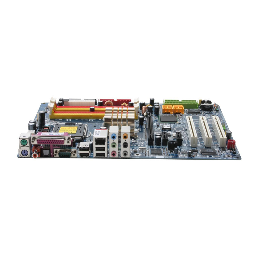
GA-8I945P Dual Graphic
GA-8I945P Dual Graphic-R
Intel
Pentium
®
®
User's Manual
Rev. 1004
12ME-945PDG-1004
This product must not be disposed of with your other household waste and must be handed over
to a designated collection point for the recycling of waste electrical and electronic equipment !
D / Pentium
4 LGA775 Processor Motherboard
®
Advertisement
Table of Contents

Related Manuals for Gigabyte GA-8I945P Dual Graphic


Summary of Contents for Gigabyte GA-8I945P Dual Graphic
- Page 1 GA-8I945P Dual Graphic GA-8I945P Dual Graphic-R Intel Pentium D / Pentium 4 LGA775 Processor Motherboard ® ® ® User's Manual Rev. 1004 12ME-945PDG-1004 This product must not be disposed of with your other household waste and must be handed over...
- Page 4 Gigabyte's prior written permission. Specifications and features are subject to change without prior notice. Product Manual Classification In order to assist in the use of this product, Gigabyte has categorized the user manual in the following: For quick installation, please refer to the "Hardware Installation Guide" included with the product.
-
Page 5: Table Of Contents
I/O Back Panel Introduction ................21 Connectors Introduction ................22 Chapter 2 BIOS Setup ....................33 The Main Menu (For example: GA-8I945P Dual Graphic /BIOS Ver. : F2b) ... 34 Standard CMOS Features ................36 Advanced BIOS Features ................38 Integrated Peripherals ................... - Page 6 Chapter 3 Install Drivers .................... 53 Install Chipset Drivers ................... 53 Software Applications ..................54 Driver CD Information ................... 54 Hardware Information ..................55 Contact Us ..................... 55 Chapter 4 Appendix ....................57 Unique Software Utilities ................57 4-1-1 EasyTune 5 Introduction ..................58 4-1-2 Xpress Recovery Introduction ................
-
Page 7: Ga-8I945P Dual Graphic Motherboard Layout
GA-8I945P Dual Graphic Motherboard Layout CPU_FAN KB_MS ATX_12V PWR_FAN COAXIAL LGA775 OPTICAL R_USB AUDIO1 F_AUDIO Intel 945P AUDIO2 IDE1 SYS_FAN Broadcom NB_FAN 5789 PCIE_16_1 F_PANEL Back BIOS PCIE_1 CLR_CMOS ICH7R CD_IN Main PCIE_16_2 BIOS CODEC PCI1 TSB82AA2 PCI2 IT8712 IDE3... -
Page 8: Ga-8I945P Dual Graphic-R Motherboard Layout
GA-8I945P Dual Graphic-R Motherboard Layout CPU_FAN KB_MS ATX_12V COAXIAL LGA775 OPTICAL R_USB AUDIO1 F_AUDIO Intel 945P AUDIO2 IDE1 SYS_FAN Broadcom 5789 PCIE_16_1 F_PANEL PCIE_1 CLR_CMOS ICH7R CD_IN PCIE_16_2 BIOS CODEC PCI1 PCI2 IT8712 IDE3 PCI3 F_USB SPDIF_I GREEN_USB IDE2 RF_ID... -
Page 9: Block Diagram
IDE RAID 8 USB 33MHz Ports PS/2 KB/Mouse 3 PCI IDE2/IDE3 PCICLK (33MHz) (Note) To use a DDRII 667 memory module on the motherboard, you must install an 800/1066MHz FSB processor . Only for GA-8I945P Dual Graphic. - 9 -... - Page 10 - 10 -...
-
Page 11: Chapter 1 Hardware Installation
2. Damage as a result of violating the conditions recommended in the user manual. 3. Damage due to improper installation. 4. Damage due to use of uncertified components. 5. Damage due to use exceeding the permitted parameters. 6. Product determined to be an unofficial Gigabyte product. - 11 - Hardware Installation... -
Page 12: Feature Summary
1 RJ 45 port Supported on the Win 2000/XP operating systems (Note 1) For further CPU support information, please go to GIGABYTE's website. (Note 2) Due to standard PC architecture, a certain amount of memory is reserved for system usage and therefore the actual memory size is less than the stated amount. - Page 13 Supports Q-Flash / Dual BIOS Additional Features Supports @BIOS Supports EasyTune 5 Overclocking Over Voltage via BIOS (CPU/DDR/PCIE/FSB) Over Clock via BIOS (CPU/DDR/PCIE) Form Factor ATX form factor; 30.5cm x 23.4cm Only for GA-8I945P Dual Graphic. - 13 - Hardware Installation...
-
Page 14: Installation Of The Cpu And Heatsink
(Grasping the CPU firmly between your thumb and forefinger, carefully place it into the socket in a straight and downwards motion. Avoid twisting or bending motions that might cause damage to the CPU during installation.) GA-8I945P Dual Graphic(-R) Motherboard - 14 -... -
Page 15: Installation Of The Heatsink
1-3-2 Installation of the Heatsink Male Push Pin The top of Female Push Pin Female Push Pin Fig.1 Fig. 2 Please apply an even layer of heatsink paste on (Turning the push pin along the direction of arrow is the surface of the installed CPU. to remove the heatsink, on the contrary, is to install.) Please note the direction of arrow sign on the male push pin doesn't face inwards before installation. -
Page 16: Installing/Removing Cool-Plus (Northbridge Cooling Fan)
Memory modules are designed so that they can be inserted only in one direction. The memory capacity used can differ with each slot. Notch DDR II Only for GA-8I945P Dual Graphic. GA-8I945P Dual Graphic(-R) Motherboard - 16 -... - Page 17 GA-8I945P Dual Graphic(-R) supports the Dual Channel Technology. After oper- ating the Dual Channel Technology, the bandwidth of Memory Bus will add double. GA-8I945P Dual Graphic(-R) includes 4 DIMM sockets, and each Channel has two DIMM sockets as following: Channel A : DDR II 1, DDR II 2...
-
Page 18: Installation Of Expansion Cards
VGA card, please press the latch as the picture to the left shows to release the card. The PCIE_12V power connector supplies extra power to the PCIEx 16 slots. Connect this connector depending on your system requirements. GA-8I945P Dual Graphic(-R) Motherboard - 18 -... -
Page 19: Configuring A Quad View System
If you want to enable the Quad View function, install two similar graphics cards into PCIE x 16 slots (it is recommended to use graphics cards of identical brand and chips. For example: GIGABYTE GV-NX66T128D). If you want to set up a single graphics card system, we recommend installing the graphics card on the PCIE_16_1 slot to ensure better display performance. - Page 20 PEG; set this item to PEG2 if the card is installed in the PCIE_16_2 slot. Step 2: Graphics Cards Driver Setting For detailed information about how to install the graphics card driver, please refer to the user's manual for your graphics card. GA-8I945P Dual Graphic(-R) Motherboard - 20 -...
-
Page 21: I/O Back Panel Introduction
I/O Back Panel Introduction PS/2 Keyboard and PS/2 Mouse Connector To install a PS/2 port keyboard and mouse, plug the mouse to the upper port (green) and the keyboard to the lower port (purple). LPT (Parallel Port) The parallel port allows connection of a printer, scanner and other peripheral devices. COAXIAL (SPDIF Out) The SPDIF coaxial output port is capable of providing digital audio to external speakers or •... -
Page 22: Connectors Introduction
CD_IN ATX (Power Connector) CPU_FAN SPDIF_I SYS_FAN F_USB/GREEN_USB PWR_FAN F1_1394/F2_1394 NB_FAN RF_ID IDE1 / IDE2 / IDE3 CLR_CMOS SATAII0 / SATAII1 / SATAII2 / SATAII3 PCIE_12V F_AUDIO PWR_LED Only for GA-8I945P Dual Graphic. GA-8I945P Dual Graphic(-R) Motherboard - 22 -... - Page 23 1/2) ATX_12V/ATX (Power Connector) With the use of the power connector, the power supply can supply enough stable power to all the components on the motherboard. Before connecting the power connector, please make sure that all components and devices are properly installed. Align the power connector with its proper location on the motherboard and connect tightly.
- Page 24 6) NB_FAN (Chip Fan Connector) If you installed wrong direction, the chip fan will not work. Sometimes will damage the chip fan. (Usually black cable is GND) Pin No. Definition +12V Only for GA-8I945P Dual Graphic. GA-8I945P Dual Graphic(-R) Motherboard - 24 -...
- Page 25 7) FDD (Floppy Connector) The FDD connector is used to connect the FDD cable while the other end of the cable connects to the FDD drive. The types of FDD drives supported are: 360KB, 720KB, 1.2MB, 1.44MB and 2.88MB. Please connect the red power connector wire to the pin1 position. 8) IDE1/IDE2/IDE3 (IDE Connector) An IDE device connects to the computer via an IDE connector.
- Page 26 By default, the audio driver is configured to support HD Audio. To connect an AC97 front panel audio module to this connector, please refer to the instructions on Page 80 about the software settings. GA-8I945P Dual Graphic(-R) Motherboard - 26 -...
- Page 27 11) PWR_LED PWR_LED is connect with the system power indicator to indicate whether the system is on/off. It will blink when the system enters suspend mode. Pin No. Definition MPD+ MPD- MPD- 12) F_PANEL (Front Panel Jumper) Please connect the power LED, PC speaker, reset switch and power switch etc of your chassis front panel to the F_PANEL connector according to the pin assignment below.
- Page 28 For optional SPDIF cable, please contact your local dealer. Pin No. Definition Power SPDIFI GA-8I945P Dual Graphic(-R) Motherboard - 28 -...
- Page 29 TPB2- TPA1- No Pin Power No Pin Power TPB1+ Only for GA-8I945P Dual Graphic. TPB1- (Note) When the standby power is shut down, USB devices (example: optical mouses) will not light on during system power-off. - 29 - Hardware Installation...
- Page 30 18) CI (Chassis Intrusion, Case Open) This 2-pin connector allows your system to detect if the chassis cover is removed. You can check the "Case Opened" status in BIOS Setup. Pin No. Definition Signal GA-8I945P Dual Graphic(-R) Motherboard - 30 -...
- Page 31 19) CLR_CMOS (Clear CMOS) You may clear the CMOS data to its default values by this jumper. To clear CMOS, temporarily short 1-2 pin. Default doesn't include the "Shunter" to prevent from improper use this jumper. Open: Normal Short: Clear CMOS 20) PCIE_12V (Power Connector) The PCIE_12V power connector supplies extra power to the PCIEx 16 slots.
- Page 32 (Or you can use a metal object to connect the positive and negative pins in the battery holder to make them short for one minute). 3. Re-install the battery. 4. Plug the power cord and turn ON the computer. GA-8I945P Dual Graphic(-R) Motherboard - 32 -...
-
Page 33: Chapter 2 Bios Setup
BIOS needs to be reset to its original settings. If you wish to upgrade to a new BIOS, either Gigabyte's Q-Flash or @BIOS utility can be used. Q-Flash allows the user to quickly and easily update or backup BIOS without entering the operating system. -
Page 34: The Main Menu (For Example: Ga-8I945P Dual Graphic /Bios Ver. : F2B)
The BIOS Setup menus described in this chapter are for reference only and may differ from the exact settings for your motherboard. The Main Menu (For example: GA-8I945P Dual Graphic /BIOS Ver. : F2b) Once you enter Award BIOS CMOS Setup Utility, the Main Menu (as figure below) will appear on the screen. - Page 35 Load Fail-Safe Defaults Fail-Safe Defaults indicates the value of the system parameters which the system would be in safe configuration. Load Optimized Defaults Optimized Defaults indicates the value of the system parameters which the system would be in best performance configuration. Set Supervisor Password Change, set, or disable password.
-
Page 36: Standard Cmos Features
Capacity of currently installed hard disk. Hard drive information should be labeled on the outside drive casing. Enter the appropriate option based on this information. Cylinder Number of cylinders Head Number of heads Precomp Write precomp GA-8I945P Dual Graphic(-R) Motherboard - 36 -... - Page 37 Landing Zone Landing zone Sector Number of sectors Drive A / Drive B The category identifies the types of floppy disk drive A or drive B that has been installed in the computer. None No floppy drive installed 360K, 5.25" 5.25 inch PC-type standard drive;...
-
Page 38: Advanced Bios Features
If you want to cancel the setting of password, please just press ENTER to make [SETUP] empty. (Note) This item will show up when you install a processor which supports this function. GA-8I945P Dual Graphic(-R) Motherboard - 38 -... - Page 39 CPU Hyper-Threading Enabled Enables CPU Hyper Threading Feature. Please note that this feature is only working for operating system with multi processors mode supported. (Default value) Disabled Disables CPU Hyper Threading. Limit CPUID Max. to 3 Enabled Limit CPUID Maximum value to 3 when use older OS like NT4. Disabled Disables CPUID Limit for windows XP.
-
Page 40: Integrated Peripherals
Enable onboard 1st channel IDE port. (Default value) Disabled Disable onboard 1st channel IDE port. On-Chip Secondary PCI IDE Enabled Enable onboard 2nd channel IDE port. (Default value) Disabled Disable onboard 2nd channel IDE port. Only for GA-8I945P Dual Graphic. GA-8I945P Dual Graphic(-R) Motherboard - 40 -... - Page 41 SATA RAID / AHCI Mode RAID Set the onboard SATA controller to RAID mode. (Default value) AHCI Set the onboard SATA controller to AHCI mode. Advanced Host Controller Interface (AHCI) is an interface specification that allows the storage driver to enable advanced Serial ATA features such as Native Command Queuing and hot plug.
- Page 42 Using Parallel port as ECP & EPP mode. ECP Mode Use DMA Set ECP Mode Use DMA to 3. (Default value) Set ECP Mode Use DMA to 1. Only for GA-8I945P Dual Graphic. GA-8I945P Dual Graphic(-R) Motherboard - 42 -...
-
Page 43: Power Management Setup
Power Management Setup CMOS Setup Utility-Copyright (C) 1984-2005 Award Software Power Management Setup ACPI Suspend Type [S1(POS)] Item Help Soft-Off by PWR-BTTN [Instant-off] Menu Level PME Event Wake Up [Enabled] Power On by Ring [Enabled] Resume by Alarm [Disabled] x Date (of Month) Alarm Everyday x Time (hh:mm:ss) Alarm 0 : 0 : 0... -
Page 44: Pnp/Pci Configurations
Auto assign IRQ to PCI 1. (Default value) 3,4,5,7,9,10,11,12,14,15 Set IRQ 3,4,5,7,9,10,11,12,14,15 to PCI 1. PCI 2 IRQ Assignment Auto Auto assign IRQ to PCI 2. (Default value) 3,4,5,7,9,10,11,12,14,15 Set IRQ 3,4,5,7,9,10,11,12,14,15 to PCI 2. GA-8I945P Dual Graphic(-R) Motherboard - 44 -... -
Page 45: Pc Health Status
Monitor CPU temperature at 90 C / 194 Disabled Disable this function. (Default value) CPU/POWER /SYSTEM FAN Fail Warning Disabled Fan warning function disable. (Default value) Enabled Fan warning function enable. Only for GA-8I945P Dual Graphic. - 45 - BIOS Setup... -
Page 46: Mb Intelligent Tweaker(M.i.t.)
Set clock ratio for frequency-locked CPU to High. (Default value) Set clock ratio for frequency-locked CPU to Low. (Note) This item will show up when you install a processor which supports this function. GA-8I945P Dual Graphic(-R) Motherboard - 46 -... - Page 47 Robust Graphics Booster Select the options can enhance the VGA graphics card bandwidth to get higher performance. Auto Set Robust Graphics Booster to Auto. (Default value) Fast Set Robust Graphics Booster to Fast. Turbo Set Robust Graphics Booster to Turbo. C.I.A.2 C.I.A.2 (CPU Intelligent Acelerator 2) is designed to detect CPU loading during software program executing, and automatically adjust CPU computing power to maximize system performance.
- Page 48 Set FSB OverVoltage Control to +0.2V. +0.3V Set FSB OverVoltage Control to +0.3V. CPU Voltage Control Supports adjustable CPU Vcore from 0.8375V to 1.6000V. (Default value: Normal) Normal CPU Vcore Display your CPU Vcore Voltage. GA-8I945P Dual Graphic(-R) Motherboard - 48 -...
-
Page 49: Load Fail-Safe Defaults
: Select Item F8: Dual BIOS1/Q-Flash F10: Save & Exit Setup Load Optimized Defaults Selecting this field loads the factory defaults for BIOS and Chipset Features which the system automatically detects. Only for GA-8I945P Dual Graphic. - 49 - BIOS Setup... -
Page 50: Set Supervisor/User Password
Setup Menu. If you select "Setup" at "Password Check" in Advance BIOS Features Menu, you will be prompted only when you try to enter Setup. Only for GA-8I945P Dual Graphic. GA-8I945P Dual Graphic(-R) Motherboard - 50 -... -
Page 51: Save & Exit Setup
F8: Dual BIOS1/Q-Flash F10: Save & Exit Setup Abandon all Data Type "Y" will quit the Setup Utility without saving to RTC CMOS. Type "N" will return to Setup Utility. Only for GA-8I945P Dual Graphic. - 51 - BIOS Setup... - Page 52 GA-8I945P Dual Graphic(-R) Motherboard - 52 -...
-
Page 53: Chapter 3 Install Drivers
Chapter 3 Install Drivers Pictures below are shown in Windows XP. Insert the driver CD-title that came with your motherboard into your CD-ROM drive, the driver CD-title will auto start and show the installation guide. If not, please double click the CD-ROM device icon in "My computer", and execute the Run.exe. -
Page 54: Software Applications
Software Applications This page displays all the tools that Gigabyte developed and some free software, you can choose anyone you want and press "install" to install them. Driver CD Information This page lists the contents of software and drivers in this CD-title. -
Page 55: Hardware Information
Hardware Information This page lists all device you have for this motherboard. Contact Us Please see the last page for details. - 55 - Install Drivers... - Page 56 GA-8I945P Dual Graphic(-R) Motherboard - 56 -...
-
Page 57: Chapter 4 Appendix
Motherboard Intelligent Tweaker (M.I.T.) allows user to access and change BIOS feature settings with relative speed and ease. Through GIGABYTE M.I.T. feature the user is no longer required to switch into different modes within BIOS setup in order to change system settings such as the CPU system bus, memory timings or to enabled Gigabyte's unique C.I.A. -
Page 58: Easytune 5 Introduction
Toggles between Easy and Advance Mode Display screen Display panel of CPU frequency Function display LEDs Shows the current functions status GIGABYTE Logo Log on to GIGABYTE website Help button Display EasyTune 5 Help file Exit or Minimize button Quit or Minimize EasyTune... -
Page 59: Xpress Recovery Introduction
F9 key during computer power on. Verifying DMI Pool Data Boot from CD: Boot from CD: Xpress Recovery V1.0 (C) Copy Right 2003. GIGABYTE Technology CO. , Ltd. 1. Execute Backup Utility 2. Execute Restore Utility 3. Remove Backup Image 4. - Page 60 F9 For Xpress Recovery Press DEL to enter SETUP / Q-Flash, F9 For Xpress Recovery 08/16/2002-I845GE-6A69YG01C-00 Xpress Recovery V1.0 (C) Copy Right 2003. GIGABYTE Technology CO. , Ltd. 1. Execute Backup Utility 2. Execute Restore Utility 3. Remove Backup Image 4.
- Page 61 1. Execute Backup Utility: Press B to Backup your System or Esc to Exit The backup utility will automatically scan your system and back up data as a backup image in your hard drive. Not all systems support access to Xpress Recovery by pressing the F9 key during computer power on.
-
Page 62: Flash Bios Method Introduction
Update Main BIOS from Floppy Update Backup BIOS from Floppy Save Main BIOS to Floppy Save Backup BIOS to Floppy PgDn/PgUp: Modify : Move ESC: Reset F10: Power Off Only for GA-8I945P Dual Graphic. GA-8I945P Dual Graphic(-R) Motherboard - 62 -... - Page 63 Dual BIOS Item explanation: Wide Range Protection: Disable(Default), Enable Status 1: If any failure (ex. Update ESCD failure, checksum error or reset? occurs in the Main BIOS, just before the Operating System is loaded and after the power is on, and that the Wide Range Protection is set to "Enable", the PC will boot from Backup BIOS automatically.
- Page 64 Updating BIOS with Q-Flash Utility on Dual BIOS Motherboards. Some of Gigabyte motherboards are equipped with dual BIOS. In the BIOS menu of the motherboards supporting Q-Flash and Dual BIOS, the Q-Flash utility and Dual BIOS utility are combined in the same screen.
- Page 65 Entering the Q-Flash utility: Step1: To use Q-Flash utility, you must press Del in the boot screen to enter BIOS menu. CMOS Setup Utility-Copyright (C) 1984-2004 Award Software Standard CMOS Features Select Language Advanced BIOS Features Load Fail-Safe Defaults Integrated Peripherals Load Optimized Defaults Power Management Setup Set Supervisor Password...
- Page 66 Save Main BIOS to Floppy Save Backup BIOS to Floppy Enter : Run :Move ESC:Reset F10:Power Off After BIOS file is read, you'll see a confirmation dialog box asking you "Are you sure to update BIOS?" GA-8I945P Dual Graphic(-R) Motherboard - 66 -...
- Page 67 3. Press Y button on your keyboard after you are sure to update BIOS. Then it will begin to update BIOS. The progress of updating BIOS will be displayed. Please do not take out the floppy disk when it begins flashing BIOS. 4.
- Page 68 Set User Password PC Health Status Save & Exit Setup MB Intelligent Tweaker(M.I.T.) Exit Without Saving ESC: Quit F3: Change Language F8: Q-Flash F10: Save & Exit Setup Time, Date, Hard Disk Type... GA-8I945P Dual Graphic(-R) Motherboard - 68 -...
- Page 69 Exploring the Q-Flash utility screen The Q-FlashBIOS utility screen consists of the following key components. Q-Flash utility bar Q-Flash Utility V1.30 Flash Type/Size.........SST 49LF003A 256K Keep DMI Data Enable Task menu for Update BIOS from Floppy Q-Flash utility Save BIOS to Floppy Action bar Enter : Run :Move...
- Page 70 Press Del to enter BIOS menu after system reboots and "Load BIOS Fail-Safe Defaults". See how to Load BIOS Fail-Safe Defaults, please kindly refer to Step 6 to 7 in Part One. Congratulation!! You have updated BIOS successfully!! GA-8I945P Dual Graphic(-R) Motherboard - 70 -...
- Page 71 Windows. Just select the desired @BIOS server to download the latest version of BIOS. Fig 1. Installing the @BIOS utility Fig 2. Installation Complete and Run @BIOS Click Sart/ Programs/ GIGABYTE/@BIOS Select @BIOS item than click Install Fig 3. The @BIOS Utility Fig 4. Select the desired @BIOS server Click "...
- Page 72 III. In method I, if the BIOS file you need cannot be found in @BIOS server, please go onto Gigabyte's web site for downloading and updating it according to method II. IV. Please note that any interruption during updating will cause system unbooted.
-
Page 73: Serial Ata Bios Setting Utility Introduction
4-1-4 Serial ATA BIOS Setting Utility Introduction RAID Levels RAID (Redundant Array of Independent Disks) is a method of combining two hard disk drives into one logical unit. The advantage of an Array is to provide better performance or data fault tolerance. Fault tolerance is achieved through data redundant operation, where if one drives fails, a mirrored copy of the data can be found on another drive. - Page 74 [ DISK/VOLUME INFORMATION ] RAID Volumes : None Defined. Physical Disks : Port Driver Model Serial # Size Type/Status(Vol ID) ST3120026AS 3JT329JX 111.7GB Non-RAID Disk ST3120026AS 3JT354CP 111.7GB Non-RAID Disk ]-Select [ESC]-Exit [ENTER]-Select Menu GA-8I945P Dual Graphic(-R) Motherboard - 74 -...
- Page 75 Create RAID Volume Press Enter under Create RAID Volume to set up RAID. Intel(R) Matrix Storage Manager option ROM V5.0.0.1011 ICH7R wRAID5 Copyright(C) 2003-04 Intel Corporation. All Rights Reversed. [ CREATE VOLUME MENU ] Name : RAID_Volume0 RAID Level : RAID0(Stripe) Disks : Select Disks...
- Page 76 ]-Change [TAB]-Next [ESC]-Previous Menu [ENTER]-Select Press Enter to enter Create Volume after setting disk capacity. GA-8I945P Dual Graphic(-R) Motherboard - 76 -...
- Page 77 Press Enter under the Create Volume item. Intel(R) Matrix Storage Manager option ROM V5.0.0.1011 ICH7R wRAID5 Copyright(C) 2003-04 Intel Corporation. All Rights Reversed. [ CREATE VOLUME MENU ] Name : RAID_Volume0 RAID Level : RAID0(Stripe) Disks : Select Disks Strip Size : 128KB Capacity : 223.5 GB...
-
Page 78: Delete Raid Volume
Size Status Bootable RAID_Volume0 RAID(Stripe) 128KB 223.5GB Normal Physical Disks : Port Driver Model Serial # Size Type/Status(Vol ID) ST3120026AS 3JT329JX 111.7GB Member Disk(0) ST3120026AS 3JT354CP 111.7GB Member Disk(0) ]-Select [ESC]-Exit [ENTER]-Select Menu GA-8I945P Dual Graphic(-R) Motherboard - 78 -... - Page 79 Windows once for that hard drive. After that, the driver will not have to be installed.) (Note 1): For users without a startup disk. Use an alternative system and insert the GIGABYTE motherboard drive CD-ROM. From the CD- ROM drive (example: D:\) double click the MENU.exe file in the BootDrv folder. A command prompt window will open similar to that in Fig.
-
Page 80: 4- / 6- / 8- Channel Audio Function Introduction
Control Panel). Double-click the icon to open the Audio Control Panel. STEP 2: In the Audio Control Panel, click the Audio I/O tab. In the upper left list, click 2CH Speaker. GA-8I945P Dual Graphic(-R) Motherboard - 80 -... - Page 81 STEP 3: After a speaker or headphone is plugged into the rear Line Out jack, a small window will pop up and ask you what type of equipment is connected. Choose Headphone or Line Out depending on the device connected and click OK. The 2-channel audio setup is completed.
- Page 82 After installation of the audio driver, you should find an Audio Manager icon in your system tray (you can also find the icon in Control Panel). Double-click the icon to open the Audio Control Panel. GA-8I945P Dual Graphic(-R) Motherboard - 82 -...
- Page 83 STEP 2: In the Audio Control Panel, click the Audio I/O tab. In the upper left list, click 8CH Speaker. STEP 3: After plugging in 8-channel speakers to the rear speaker jacks, a small window will pop up and ask you what type of equipment is connected.
-
Page 84: Troubleshooting
Below is a collection of general asked questions. To check general asked questions based on a specific motherboard model, please log on to http://www.gigabyte.com.tw Question 1: I cannot see some options that were included in previous BIOS after updating BIOS. Why? Answer: Some advanced options are hidden in new BIOS version. - Page 85 - 85 - Appendix...
- Page 86 GA-8I945P Dual Graphic(-R) Motherboard - 86 -...
- Page 87 Contact Us Taiwan (Headquarters) Japan GIGA-BYTE TECHNOLOGY CO., LTD. NIPPON GIGA-BYTE CORPORATION Address: No.6, Bau Chiang Road, Hsin-Tien, Taipei 231, WEB address : http://www.gigabyte.co.jp Taiwan Singapore TEL: +886-2-8912-4888 GIGA-BYTE SINGAPORE PTE. LTD. FAX: +886-2-8912-4003 Tech. Support : Tech. Support : http://tw.giga-byte.com/TechSupport/ServiceCenter.htm...
- Page 88 Romania WEB address : http://www.giga-byte.com.au Tech. Support : France http://tw.giga-byte.com/TechSupport/ServiceCenter.htm GIGABYTE TECHNOLOGY FRANCE S.A.R.L. Non-Tech. Support(Sales/Marketing) : Tech. Support : http://ggts.gigabyte.com.tw/nontech.asp http://tw.giga-byte.com/TechSupport/ServiceCenter.htm WEB address: http://www.gigabyte.com.ro Non-Tech. Support(Sales/Marketing) : http://ggts.gigabyte.com.tw/nontech.asp WEB address : http://www.gigabyte.fr GA-8I945P Dual Graphic(-R) Motherboard - 88 -...
Need help?
Do you have a question about the GA-8I945P Dual Graphic and is the answer not in the manual?
Questions and answers