
Related Manuals for Gigabyte GA-8I915ME Series


Summary of Contents for Gigabyte GA-8I915ME Series
- Page 1 GA-8I915ME Series Intel Pentium 4 LGA775 Processor Motherboard ® ® User's Manual Rev. 1002 12ME-I915MES-1002...
- Page 3 Copyright © 2005 GIGA-BYTE TECHNOLOGY CO., LTD. All rights reserved. The trademarks mentioned in the manual are legally registered to their respective companies. Notice The written content provided with this product is the property of Gigabyte. No part of this manual may be reproduced, copied, translated, or transmitted in any form or by any means without Gigabyte's prior written permission.
-
Page 4: Table Of Contents
Table of Content GA-8I915ME Series Motherboard Layout ..............6 Block Diagram ........................ 7 Chapter 1 Hardware Installation ..................9 Considerations Prior to Installation ..............9 Feature Summary ..................10 Installation of the CPU and Heatsink .............. 12 1-3-1 Installation of the CPU ..................12 1-3-2 Installation of the Heatsink .................. - Page 5 Chapter 3 Install Drivers ..................... 51 Install Chipset Drivers ..................51 Software Applications ..................52 Driver CD Information ..................52 Hardware Information ..................53 Contact Us ..................... 53 Chapter 4 Appendix ....................55 Unique Software Utilities ................55 4-1-1 EasyTune 5 Introduction ..................56 4-1-2 Xpress Recovery Introduction ................
-
Page 6: Ga-8I915Me Series Motherboard Layout
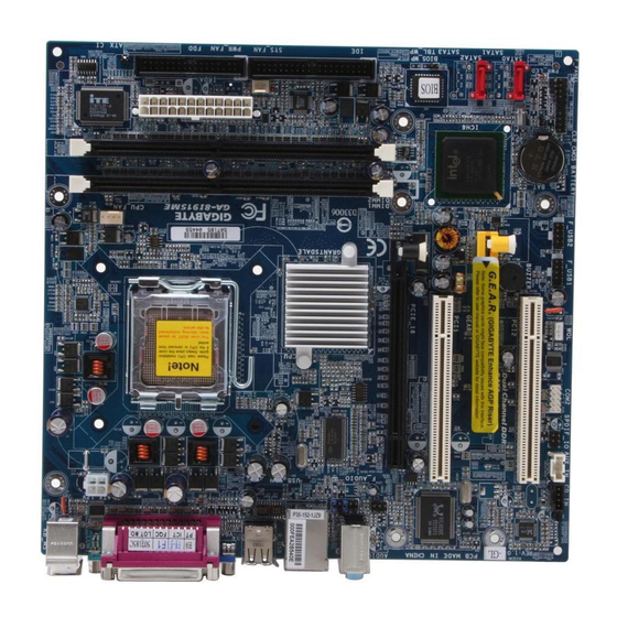
GA-8I915ME Series Motherboard Layout KB_MS CPU_FAN ATX_12V LGA775 R_USB Intel 915GV Intel 915GL Intel 910GL Intel 915G AUDIO1 PCIE_16 SUR_CEN PCI1 BIOS BIOS_WP RTL8100C RTL8110S SATA2 ICH6 GEAR SATA0 PCI2 BUZZER PWR_LED CODEC F_USB1 F_USB2 SPDIF_IO COM2 F_PANEL CD_IN AUX_IN Only for GA-8I915ME-GV. -
Page 7: Block Diagram
Block Diagram CPUCLK+/-(200 /133 MHz) LGA775 Processor PCI-ECLK Host (100MHz) Interface DDR400/333MHz DIMM Intel Intel 915GV Dual Channel Memory PCI Express x16 Intel 915GL Intel 910GL GMCHCLK (200/133MHz) Intel 915G GMCH 66MHz 33MHz 14.318MHz 48MHz PCI Express x4 BIOS PCI Bus 2 Serial ATA Intel ICH6... - Page 8 - 8 -...
-
Page 9: Chapter 1 Hardware Installation
Chapter 1 Hardware Installation Considerations Prior to Installation Preparing Your Computer The motherboard contains numerous delicate electronic circuits and components which can become damaged as a result of electrostatic discharge (ESD). Thus, prior to installation, please follow the instructions below: 1. -
Page 10: Feature Summary
Feature Summary Motherboard GA-8I915ME Series motherboard -GA-8I915ME-GV / GA-8I915ME-GL / GA-8I915ME-C / GA-8I915ME-G Supports the latest Intel Pentium 4 LGA775 CPU ® ® Supports 800 / 533MHz FSB L2 cache varies with CPU Chipset Northbridge: Intel 915GV /915GL /910GL /915G Express chipset ®... - Page 11 Hardware Monitor System voltage detection CPU temperature detection CPU / System fan speed detection CPU warning temperature CPU / System fan failure warning CPU smart fan control BIOS Use of licensed AWARD BIOS Supports Q-Flash Additional Features Supports @BIOS Supports EasyTune 5 (only supports Hardware Monitor function) Overclocking Over Clock via BIOS (DDR) Form Factor...
-
Page 12: Installation Of The Cpu And Heatsink
(Grasping the CPU firmly between your thumb and forefinger, carefully place it into the socket in a straight and downwards motion. Avoid twisting or bending motions that might cause damage to the CPU during installation.) GA-8I915ME Series Motherboard - 12 -... -
Page 13: Installation Of The Heatsink
1-3-2 Installation of the Heatsink Male Push Pin The top of Female Push Pin Female Push Pin Fig. 2 Fig.1 Please apply an even layer of heatsink paste on (Turning the push pin along the direction of arrow the surface of the installed CPU. is to remove the heatsink, on the contrary, is to install.)Please note the direction of arrow sign on the male push pin doesn't face inwards before... -
Page 14: Installation Of Memory
DIMM slot. Then push it down. 3. Close the plastic clip at both edges of the DIMM slots to lock the DIMM module. Reverse the installation steps when you wish to remove the DIMM module. GA-8I915ME Series Motherboard - 14 -... - Page 15 Dual Channel DDR GA-8I915ME-GV/GA-8I915ME-GL/GA-8I915ME-C/GA-8I915ME-G supports the Dual Channel Technology. After operating the Dual Channel Technology, the bandwidth of Memory Bus will add double. GA-8I915ME-GV/GA-8I915ME-GL/GA-8I915ME-C/GA-8I915ME-G includes 2 DIMM sockets, and each Channel has two DIMM sockets as following: Channel A : DIMM1 Channel B : DIMM2 If you want to operate the Dual Channel Technology, please note the following explanations due to the limitation of Intel chipset specifications.
-
Page 16: Installation Of Expansion Cards
VGA card. Please align the VGA card to the onboard PCI Express x 16/G.E.A.R. slot and press firmly down on the slot .Make sure your VGA card is locked by the small white- drawable bar. GA-8I915ME Series Motherboard - 16 -... -
Page 17: What Is G.e.a.r
1-5-1 What is G.E.A.R.? The revolutionary and innovative G.E.A.R. (GIGABYTE Enhance AGP Riser) interface provides an additional interface for traditional AGP Graphics card on Intel chipset based PCI Express solution motherboard. It supports most of the AGP Graphics card available in the market from AGP 4X to AGP 8X graphics card. - Page 18 GV-NX53128D Gigabyte GV-NX57128D Gigabyte GV-NX59128D Gigabyte GV-NX62128D Gigabyte GV-NX66256D Gigabyte GV-NX66T128VP Gigabyte G V-NX66T128D Gigabyte G V-NX68T256DH Gigabyte G V-NX55128DP Gigabyte G V-NX68U256D Gigabyte G V-NX62TC256D A S U S EN6600/TD/128 To be continued... GA-8I915ME Series Motherboard - 18 -...
- Page 19 Figure 3. PCI Express x16 Card Graphics Chip Maker Model Name Gigabyte GV-RX30S128D Gigabyte GV-RX60P128D Gigabyte GV-RX60X128V Gigabyte GV-RX70128D Gigabyte GV-RX70P128D Gigabyte GV-RX80T256V Gigabyte G V-RX80L256V Gigabyte G V-RX80256D A S U S AX800XT A S U S AX700PRO RX600 XT-TD128 - 19 - Hardware Installation...
-
Page 20: I/O Back Panel Introduction
Connect the stereo speakers, earphone or front surround speakers to this connector. MIC In Microphone can be connected to MIC In jack. You can use audio software to configure 2-/4-/6- channel audio functioning. Only for GA-8I915ME-GV. Only for GA-8I915ME-GL. Only for GA-8I915ME-C. Only for GA-8I915ME-G. GA-8I915ME Series Motherboard - 20 -... -
Page 21: Connectors Introduction
Connectors Introduction ATX_12V F_AUDIO ATX (Power Connector) CD_IN CPU_FAN AUX_IN SYS_FAN F_USB1 / F_USB2 COM2 SUR_CEN SATA0 / SATA2 SPIDF_IO F_PANEL CLR_CMOS PWR_LED BIOS_WP - 21 - Hardware Installation... - Page 22 ; Otherwise, please do not remove it. Pin No. Definition +12V +12V Pin No. Definition 3.3V 3.3V Power Good 5V SB(stand by +5V) +12V +12V 3.3V(Only for 24pins ATX) 3.3V -12V PS_ON(soft On/Off) GA-8I915ME Series Motherboard - 22 -...
- Page 23 3/4) CPU_FAN / SYS_FAN (Cooler Fan Power Connector) The cooler fan power connector supplies a +12V power voltage via a 3-pin/4-pin (only for CPU_FAN) power connector and possesses a foolproof connection design. Most coolers are designed with color-coded power connector wires. A red power connector wire indicates a positive connection and requires a +12V power voltage.
- Page 24 7) SATA0/SATA2 (Serial ATA Connector, Controlled by ICH6) Serial ATA can provide up to 150MB/s transfer rate. Please refer to the BIOS setting for the Serial ATA and install the proper driver in order to work properly. Pin No. Definition GA-8I915ME Series Motherboard - 24 -...
-
Page 25: Front Panel Jumper
8) F_PANEL (Front Panel Jumper) Please connect the power LED, PC speaker, reset switch and power switch etc of your chassis front panel to the F_PANEL connector according to the pin assignment below. Power Message LED/ Switch Speaker Connector Power/ Sleep LED IDE Hard Disk Reset Switch... - Page 26 If you want to use "Front Audio" connector, you must remove the jumpers on pin 5-6, 9-10. Pin No. Definition MIC_BIAS POWER FrontAudio(R) Rear Audio (R)/ Return R No Pin FrontAudio (L) Rear Audio (L)/ Return L GA-8I915ME Series Motherboard - 26 -...
- Page 27 12) CD_IN (CD IN) Connect CD-ROM or DVD-ROM audio out to the connector. Pin No. Definition CD-L CD -R 13) AUX_IN (AUX In Connector) Connect other device (such as PCI TV Tuner audio out) to the connector. Pin No. Definition AUX-L AUX-R - 27 -...
- Page 28 For optional COM cable, please contact your local dealer. Pin No. Definition NDCD B- NSIN B NSOUT B NDTR B- NDSR B- NRTS B- NCTS B- NRI B- No Pin GA-8I915ME Series Motherboard - 28 -...
- Page 29 16) SUR_CEN Please contact your nearest dealer for optional SUR_CEN cable. Pin No. Definition SUR OUTL SUR OUTR No Pin CENTER_OUT BASS_OUT 17) SPDIF_IO (SPDIF In/ Out) The SPDIF output is capable of providing digital audio to external speakers or compressed AC3 data to an external Dolby Digital Decoder.
- Page 30 You may clear the CMOS data to its default values by this jumper. To clear CMOS, temporarily short 1-2 pin. Default doesn't include the "Shunter" to prevent from improper use this jumper. Open: Normal Short :Clear CMOS GA-8I915ME Series Motherboard - 30 -...
- Page 31 20) BIOS_WP (BIOS Write Protect) Open: Normal Short :Write Protect 21) BAT(Battery) If you want to erase CMOS... 1.Turn OFF the computer and unplug the power cord. 2. Take out the battery gently and put it aside for about 10 minutes (Or you can use a metal object to connect the positive and negative pins in the battery holder to make them short for one minute).
- Page 32 GA-8I915ME Series Motherboard - 32 -...
-
Page 33: Chapter 2 Bios Setup
Chapter 2 BIOS Setup BIOS (Basic Input and Output System) includes a CMOS SETUP utility which allows user to configure required settings or to activate certain system features. The CMOS SETUP saves the configuration in the CMOS SRAM of the motherboard. When the power is turned off, the battery on the motherboard supplies the necessary power to the CMOS SRAM. -
Page 34: The Main Menu
Frequency / Voltage Control This setup page is control CPU clock and frequency ratio. Load Fail-Safe Defaults Fail-Safe Defaults indicates the value of the system parameters which the system would be in safe configuration. GA-8I915ME Series Motherboard - 34 -... - Page 35 Load Optimized Defaults Optimized Defaults indicates the value of the system parameters which the system would be in best performance configuration. Set Supervisor Password Change, set, or disable password. It allows you to limit access to the system and Setup, or just to Setup. Set User Password Change, set, or disable password.
-
Page 36: Standard Cmos Features
Cylinder Number of cylinders Head Number of heads Precomp Write precomp Landing Zone Landing zone Sector Number of sectors If a hard disk has not been installed, select NONE and press <Enter>. GA-8I915ME Series Motherboard - 36 -... - Page 37 Drive A / Drive B The category identifies the types of floppy disk drive A or drive B that has been installed in the computer. None No floppy drive installed 360K, 5.25" 5.25 inch PC-type standard drive; 360K byte capacity. 1.2M, 5.25"...
-
Page 38: Advanced Bios Features
The system will not boot and will not access to Setup page if the correct password is not entered at the prompt. (Note3) This item will show up when you install a processor which supports this function. GA-8I915ME Series Motherboard - 38 -... - Page 39 CPU Hyper-Threading Enabled Enables CPU Hyper Threading Feature. Please note that this feature is only working for operating system with multi processors mode supported. (Default value) Disabled Disables CPU Hyper Threading. Limit CPUID Max. to 3 Enabled Limit CPUID Maximum value to 3 when use older OS like NT4. Disabled Disables CPUID Limit for windows XP.(Default value) Init Display First...
-
Page 40: Integrated Peripherals
Enable USB Controller. (Default value) Disabled Disable USB Controller. USB 2.0 Controller Disable this function if you are not using onboard USB 2.0 feature. Enabled Enable USB 2.0 Controller. (Default value) Disabled Disable USB 2.0 Controller. GA-8I915ME Series Motherboard - 40 -... - Page 41 USB Keyboard Support Enabled Enable USB Keyboard Support. Disabled Disable USB Keyboard Support. (Default value) USB Mouse Support Enabled Enable USB Mouse Support. Disabled Disable USB Mouse Support. (Default value) AC97 Audio Auto Auto detect AC97 audio function. (Default value) Disabled Disable AC97 audio function.
-
Page 42: Power Management Setup
Time (hh: mm: ss) Alarm : (0~23) : (0~59) : (0~59) Power On By Mouse Disabled Disable this function. (Default value) Double Click Double click on PS/2 mouse left button to power on the system. GA-8I915ME Series Motherboard - 42 -... - Page 43 Power On By Keyboard Password Enter from 1 to 5 characters to set the Keyboard Power On Password. Disabled Disabled this function. (Default value) Keyboard 98 If your keyboard have "POWER Key" button, you can press the key to power on the system. KB Power ON Password When "Power On by Keyboard"...
-
Page 44: Pnp/Pci Configurations
SYSTEM FAN Fail Warning [Disabled] CPU Smart FAN Control [Enabled] CPU Smart FAN Mode [Auto] : Move Enter: Select +/-/PU/PD: Value F10: Save ESC: Exit F1: General Help F5: Previous Values F6: Fail-Save Default F7: Optimized Defaults GA-8I915ME Series Motherboard - 44 -... - Page 45 Reset Case Open Status Disabled Don't reset case open status. (Default value) Enabled Clear case open status at next boot. Case Opened If the case is closed, "Case Opened" will show "No". If the case have been opened, "Case Opened" will show "Yes". If you want to reset "Case Opened"...
-
Page 46: Frequency/Voltage Control
Set Memory frequency by DRAM SPD data. (Default value) Memory Frequency (Mhz) The values depend on "System Memory Multiplier" item. (Note) This item will show up when you install a processor which supports this function. GA-8I915ME Series Motherboard - 46 -... -
Page 47: Load Fail-Safe Defaults
Load Fail-Safe Defaults CMOS Setup Utility-Copyright (C) 1984-2005 Award Software Standard CMOS Features Load Fail-Safe Defaults Advanced BIOS Features Load Optimized Defaults Integrated Peripherals Set Supervisor Password Power Management Setup Set User Password Load Fail-Safe Defaults (Y/N)? N PnP/PCI Configurations Save &... -
Page 48: Set Supervisor/User Password
Setup Menu. If you select "Setup" at "Password Check" in Advance BIOS Features Menu, you will be prompted only when you try to enter Setup. GA-8I915ME Series Motherboard - 48 -... -
Page 49: Save & Exit Setup
2-11 Save & Exit Setup CMOS Setup Utility-Copyright (C) 1984-2005 Award Software Standard CMOS Features Load Fail-Safe Defaults Advanced BIOS Features Load Optimized Defaults Integrated Peripherals Set Supervisor Password Power Management Setup Set User Password PnP/PCI Configurations Save & Exit Setup PC Health Status Save to CMOS and EXIT (Y/N)? Y Exit Without Saving... - Page 50 GA-8I915ME Series Motherboard - 50 -...
-
Page 51: Chapter 3 Install Drivers
Chapter 3 Install Drivers Pictures below are shown in Windows XP. Insert the driver CD-title that came with your motherboard into your CD-ROM drive, the driver CD-title will auto start and show the installation guide. If not, please double click the CD-ROM device icon in "My computer", and execute the Run.exe. -
Page 52: Software Applications
This page displays all the tools that Gigabyte developed and some free software, you can choose anyone you want and press "install" to install them. Driver CD Information This page lists the contents of software and drivers in this CD-title. GA-8I915ME Series Motherboard - 52 -... -
Page 53: Hardware Information
Hardware Information This page lists all device you have for this motherboard. Contact Us Please see the last page for details. - 53 - Install Drivers... - Page 54 GA-8I915ME Series Motherboard - 54 -...
-
Page 55: Chapter 4 Appendix
Chapter 4 Appendix Unique Software Utilities (Not all model support these Unique Software Utilities, please check your MB features.) U-PLUS D.P.S. (Universal Plus Dual Power System) The U-Plus Dual Power System (U-Plus DPS) is a revolutionary eight-phase power circuit built for ultimate system protection. -
Page 56: Easytune 5 Introduction
GIGABYTE Logo Log on to GIGABYTE website Help button Display EasyTune 5 Help file Exit or Minimize button Quit or Minimize EasyTune 5 software (Note) EasyTune 5 functions may vary depending on different motherboards. GA-8I915ME Series Motherboard - 56 -... -
Page 57: Xpress Recovery Introduction
F9 key during computer power on. Verifying DMI Pool Data Boot from CD: Boot from CD: Xpress Recovery V1.0 (C) Copy Right 2003. GIGABYTE Technology CO. , Ltd. 1. Execute Backup Utility 2. Execute Restore Utility 3. Remove Backup Image 4. - Page 58 F9 For Xpress Recovery Press DEL to enter SETUP / Q-Flash, F9 For Xpress Recovery 08/16/2002-I845GE-6A69YG01C-00 Xpress Recovery V1.0 (C) Copy Right 2003. GIGABYTE Technology CO. , Ltd. 1. Execute Backup Utility 2. Execute Restore Utility 3. Remove Backup Image 4.
- Page 59 1. Execute Backup Utility: Press B to Backup your System or Esc to Exit The backup utility will automatically scan your system and back up data as a backup image in your hard drive. Not all systems support access to Xpress Recovery by pressing the F9 key during computer power on.
-
Page 60: Flash Bios Method Introduction
Please note that because updating BIOS has potential risk, please do it with caution!! We are sorry that Gigabyte Technology Co., Ltd is not responsible for damages of system because of incorrect manipulation of updating BIOS to avoid any claims from end-users. - Page 61 Entering the Q-Flash utility: Step1: To use Q-Flash utility, you must press Del in the boot screen to enter BIOS menu. CMOS Setup Utility-Copyright (C) 1984-2004 Award Software Standard CMOS Features Select Language Advanced BIOS Features Load Fail-Safe Defaults Integrated Peripherals Load Optimized Defaults Power Management Setup Set Supervisor Password...
- Page 62 Save Main BIOS to Floppy Save Backup BIOS to Floppy Enter : Run :Move ESC:Reset F10:Power Off After BIOS file is read, you'll see a confirmation dialog box asking you "Are you sure to update BIOS?" GA-8I915ME Series Motherboard - 62 -...
- Page 63 3. Press Y button on your keyboard after you are sure to update BIOS. Then it will begin to update BIOS. The progress of updating BIOS will be displayed. Please do not take out the floppy disk when it begins flashing BIOS. 4.
-
Page 64: Updating Bios With Q-Flash Utility On Single-Bios Motherboards
PnP/PCI Configurations Set User Password PC Health Status Save & Exit Setup MB Intelligent Tweaker(M.I.T.) Exit Without Saving ESC: Quit F3: Change Language F8: Q-Flash F10: Save & Exit Setup Time, Date, Hard Disk Type... GA-8I915ME Series Motherboard - 64 -... - Page 65 Exploring the Q-Flash utility screen The Q-FlashBIOS utility screen consists of the following key components. Q-Flash utility bar Q-Flash Utility V1.30 Flash Type/Size.........SST 49LF003A 256K Task menu for Keep DMI Data Enable Update BIOS from Floppy Q-Flash utility Save BIOS to Floppy Action bar Enter : Run :Move...
- Page 66 Press Del to enter BIOS menu after system reboots and "Load BIOS Fail-Safe Defaults". See how to Load BIOS Fail-Safe Defaults, please kindly refer to Step 6 to 7 in Part One. Congratulation!! You have updated BIOS successfully!! GA-8I915ME Series Motherboard - 66 -...
- Page 67 Method 2 : @BIOS Utility If you do not have a DOS startup disk, we recommend that you use the new @BIOS utility. @BIOS allows users to update their BIOS under Windows. Just select the desired @BIOS server to download the latest version of BIOS.
- Page 68 Gigabyte's web site for downloading and updating it according to method II. IV. Please note that any interruption during updating will cause system unbooted. V. Do not use @BIOS and C.O.M. (Corporate Online Management) at the same time. GA-8I915ME Series Motherboard - 68 -...
-
Page 69: 4- / 6- Channel Audio Function Introduction
4-1-4 2 / 4 / 6 Channel Audio Function Introduction 2 Channel Audio Setup We recommend that you use speakers with amplifier to get the best sound effect if the stereo output is applied. STEP 1: Connect the stereo speakers or earphone to "Line Out."... - Page 70 Clear the Only SURROUND-KIT check box and press OK. When the Environment setting is None, the sound would be performed as stereo mode (2-channel output). Please select other settings (ex: Living Room) for 4-channel output. GA-8I915ME Series Motherboard - 70 -...
- Page 71 Basic 6 Channel Analog Audio Output Mode Use the back audio panel to connect the audio output without any additional module. STEP 1: Connect the front channels to "Line Out",the rear Line In channels to "Line In", and the Center/Subwoofer channels to "MIC In".
- Page 72 GIGABYTE unique "Audio Combo Kit" as picture. STEP 1: Secure the metal bracket of the"Surround Kit" to the chassis back panel with a screw. STEP 2: Connect the "SURROUND-KIT" cable to the SUR_CEN connector on the M/B. GA-8I915ME Series Motherboard - 72 -...
- Page 73 STEP 3: Connect the front channels to back audio panel's "Line Out", the rear channels to SURROUND-KIT's REAR R/L, and the Center/Subwoofer channels to SURROUND-KIT's SUB CENTER. STEP 4: After installing the audio driver, you'll find a Sound Effect icon on the lower right hand taskbar.
- Page 74 Secure the metal bracket of the SPDIF Output device to the chassis back panel with a screw. STEP 2: Connect the SPDIF device cable to the SPDIF_IO connector on the motherboard. STEP 3: Connect SPDIF to the SPDIF decoder. GA-8I915ME Series Motherboard - 74 -...
-
Page 75: Jack-Sensing Introduction
Jack-Sensing Introuction Jack-Sensing provides audio connectors error-detection function. Install Microsoft DirectX8.1 first to enable Jack-Sensing support for Windows 98SE/2000 /ME. Jack-Sensing includes 2 parts: AUTO and MANUAL. Following is an example for 2 channels (Windows XP): Introduction of audio connectors You may connect CDROM, Walkman or other audio input devices to Line In jack, speakers, earphone, other output devices to Line Out jack,... - Page 76 If you set wrong with the connectors, the warning message will come out as right picture. Manual setting: If the device picture shows different from what you set, please press "Manual Selection" to set. GA-8I915ME Series Motherboard - 76 -...
-
Page 77: Troubleshooting
Troubleshooting Below is a collection of general asked questions. To check general asked questions based on a specific motherboard model, please log on to http://www.gigabyte.com.tw Question 1: I cannot see some options that were included in previous BIOS after updating BIOS. Why? Answer: Some advanced options are hidden in new BIOS version. - Page 78 GA-8I915ME Series Motherboard - 78 -...
- Page 79 Contact Us Taiwan (Headquarters) Japan GIGA-BYTE TECHNOLOGY CO., LTD. NIPPON GIGA-BYTE CORPORATION Address: No.6, Bau Chiang Road, Hsin-Tien, Taipei 231, WEB address : http://www.gigabyte.co.jp Taiwan Singapore TEL: +886-2-8912-4888 GIGA-BYTE SINGAPORE PTE. LTD. FAX: +886-2-8912-4003 Tech. Support : Tech. Support : http://tw.giga-byte.com/TechSupport/ServiceCenter.htm http://tw.giga-byte.com/TechSupport/ServiceCenter.htm Non-Tech.
- Page 80 CZECH REPUBLIC Shenyang Tech. Support : TEL: +86-24-23960918 http://tw.giga-byte.com/TechSupport/ServiceCenter.htm FAX: +86-24-23960918-809 Non-Tech. Support(Sales/Marketing) : Australia http://ggts.gigabyte.com.tw/nontech.asp GIGABYTE TECHNOLOGY PTY. LTD. WEB address: http://www.gigabyte.cz Tech. Support : Romania http://tw.giga-byte.com/TechSupport/ServiceCenter.htm Representative Office Of GIGA-BYTE Technology Co., Ltd. in Non-Tech. Support(Sales/Marketing) : Romania http://ggts.gigabyte.com.tw/nontech.asp Tech.
Need help?
Do you have a question about the GA-8I915ME Series and is the answer not in the manual?
Questions and answers