Table of Contents
Advertisement
DECLARATION OF CONFORMITY
Per FCC Part 2 Section 2. 1077(a)
Responsible Party Name: G.B.T. INC.
Address: 18305 Valley Blvd., Suite#A
LA Puent, CA 91744
Phone/Fax No: (818) 854-9338/ (818) 854-9339
hereby declares that the product
Product Name:
Mother Board
Model Number:
GA-7ZX
Conforms to the following specifications:
FCC Part 15, Subpart B, Section 15.107(a) and Section 15.109(a),
Class B Digital Device
Supplementary Information:
This device complies with part 15 of the FCC Rules. Operation is subject to the
following two conditions:
(1)
This device may not cause harmful
and
(2)
this device must accept any inference received, including
that may cause undesired operation.
Representative Person's Name:
ERIC LU
Eric Lu
Signature:
Date:
Mar. 20, 2001
determined by turning the equipment off and on, the user is encouraged to try to
correct the interference by one or more of the following measures:
-Reorient or relocate the receiving antenna
-Move the equipment away from the receiver
-Plug the equipment into an outlet on a circuit different from that to which
the receiver is connected
-Consult the dealer or an experienced radio/television technician for
additional suggestions
You are cautioned that any change or modifications to the equipment not
expressly approve by the party responsible for compliance could void Your
authority to operate such equipment.
This device complies with Part 15 of the FCC Rules. Operation is subjected to
the following two conditions 1) this device may not cause harmful interference
and 2) this device must accept any interference received, including interference
that may cause undesired operation.
FCC Compliance Statement:
This equipment has been tested and found to
comply with limits for a Class B digital device,
pursuant to Part 15 of the FCC rules. These
limits are designed to provide reasonable
protection
against
residential
installations.
generates,
uses,
frequency energy, and if not installed and used
in accordance with the instructions, may cause
harmful interference to radio communications.
However, there is no guarantee that interference
will not occur in a particular installation. If this
equipment does cause interference to radio or
television equipment reception, which can be
harmful
interference
This
equipment
and
can
radiate
in
radio
Advertisement
Table of Contents

Related Manuals for Gigabyte GA-7ZX


Summary of Contents for Gigabyte GA-7ZX
- Page 1 Phone/Fax No: (818) 854-9338/ (818) 854-9339 hereby declares that the product Product Name: Mother Board Model Number: GA-7ZX Conforms to the following specifications: FCC Part 15, Subpart B, Section 15.107(a) and Section 15.109(a), Class B Digital Device Supplementary Information: This device complies with part 15 of the FCC Rules. Operation is subject to the...
-
Page 2: Declaration Of Conformity
Safety of household and similar electrical appliances (Stamp) Declaration of Conformity We, Manufacturer/Importer (full address) G.B.T. Technology Träding GMbH declare that the product Mother Board GA-7ZX is in conformity with EN 61000-3-2* EN60555-2 EN61000-3-3* EN60555-3 EN 50081-1 EN 50082-1 EN 55081-2... - Page 3 7ZX Series AMD Athlon /Duron Socket A Processor Motherboard USER'S MANUAL AMD Athlon /Duron Socket A Processor Motherboard REV. 5.1 First Edition R-51-01-010309...
- Page 5 How This Manual Is Organized This manual is divided into the following sections: 1) Revision History 2) Item Checklist 3) Features 4) Hardware Setup 5) Performance & Block Diagram 6) Suspend to RAM & Dual BIOS 7) Four Speaker & SPDIF 8) @BIOS &...
-
Page 7: Table Of Contents
Revision History Item Checklist Summary of Features 7ZX Series Motherboard Layout Page Index for CPU Speed Setup / Connectors / Panel and Jumper Definition Performance List Block Diagram Suspend to RAM Installation Dual BIOS Introduction (Optional) Four Speaker & SPDIF Introduction (Optional) @BIOS Introduction EasyTune III... -
Page 8: Revision History
7ZX Series Motherboard Revision History Revision Revision Note Initial release of the 7ZX Series motherboard user’s manual. The author assumes no responsibility for any errors or omissions that may appear in this document nor does the author make a commitment to update the information contained herein. Third-party brands and names are the property of their respective owners. -
Page 9: Item Checklist
Item Checklist Item Checklist The 7ZX Series motherboard Cable for IDE / floppy device CD (TUCD) for motherboard driver & utility 7ZX Series user’s manual... -
Page 10: Summary Of Features
7ZX Series Motherboard Summary Of Features Form Factor Motherboard Chipset Apollo KT133, consisting of: Clock Generator Memory I/O Control Slots On-Board IDE On-Board Peripherals Hardware Monitor 30.5 cm x 22.8 cm ATX size form factor, 4 layers PCB. 7ZX series includes 7ZX, 7ZX-1 AMD Athlon /Duron (K7) Socket A Processor... - Page 11 PS/2 Connector On-Board Sound BIOS Additional Features PS/2 Keyboard interface and PS/2 Mouse interface Creative CT5880 sound (Optional) AC’97 CODEC Line In/Line Out/Mic In/AUX In/CD In/TEL/Game Port /Four Speaker & SPDIF (Optional) Licensed AMI BIOS, 2M bit flash ROM Support Dual BIOS (Optional) Support Wake-On-LAN (WOL) Support Internal / External Modem Ring On Support USB KB/MS Wake up from S3-S5...
-
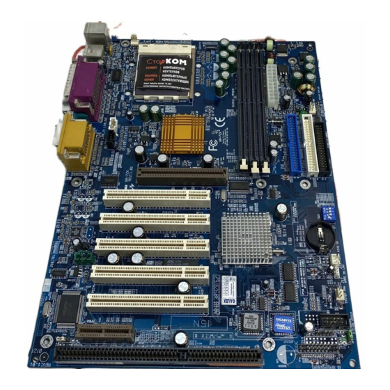
Page 12: 7Zx Series Motherboard Layout
7ZX Series Motherboard 7ZX Series Motherboard Layout PS/2 Socket A CPU AGP 1 PCI1 PCI2 PCI3 PCI4 Creative PCI5 CT5880 JP16 JP18 ISA 1 VT8363E (VT8363A) Clock Generator VT82C 686B MAIN BIOS JP17 LED1 JP21 BAT1 BACK Up USB2 BIOS... -
Page 13: Page Index For Cpu Speed Setup / Connectors / Panel And Jumper
Page Index for CPU Speed Setup/Connectors/Panel and Jumper Definition CPU Speed Setup Connectors Game & Audio Port COM A / COM B / LPT Port USB 1 Connector USB 2 Connector PS/2 Keyboard & PS/2 Mouse Connector J3 (CPU Fan) JP6 (Power Fan) J2 (System Fan) ATX Power... -
Page 14: Definition
7ZX Series Motherboard CPU Speed Setup The system bus speed is selectable at 100~133MHz. The user can select the system bus speed by DIP switch SW1 & JP21. Set System Bus Speed SW1: JP21: CPU Clock Frequency (Optional) The FSB Speed of the 7ZX(VIA KT133A) is 100/133MHz. The FSB Speed of the 7ZX-1(VIA KT133E) is 100MHz. -
Page 15: Lpt Port
Connectors Game & Audio Port COM A / COM B / LPT Port MIC In Line Out 1 Line In / Line Out 2 Line Out 1: Line Out or SPDIF (The SPDIF output is capable of providing digital audio to external speakers or compressed AC3 data to an external Dolby digital decoder). - Page 16 7ZX Series Motherboard USB 1 Connector USB 2 Connector Pin No. Definition USB V0 USB D0- USB D0+ USB V1 5 6 7 8 USB D1- USB D1+ Pin No. Definition USB D2- USB D2+ USB D3+ USB D3-...
- Page 17 PS/2 Keyboard & PS/2 Mouse Connector J3: CPU Fan PS/2 Mouse Mouse/Keyboard Pin No. PS/2 Keyboard Pin No. Definition Control +12V SENSE Connectors PS/2 Definition Data VCC(+5V) Clock...
- Page 18 7ZX Series Motherboard JP6: Power Fan J2: Sysem Fan Pin No. Definition Control +12V Pin No. Definition Control +12V SENSE...
- Page 19 ATX Power Floppy Port Pin No. Definition 3,5,7,13, 15-17 1,2,11 4,6,19,20 Power Good 5V SB (stand by+5V) PS-ON (Soft On/Off) Red Line FDD1 Connectors 3.3V +12V -12V...
- Page 20 7ZX Series Motherboard IDE1 (Primary), IDE2 (Secondary) Port J16 TEL: The connector is for Modem with internal voice connector Red Line IDE 1 IDE 2 Pin No. Definition Signal-In Signal-Out...
- Page 21 J15: AUX_IN J18: CD Audio Line In Pin No. Definition AUX-L AUX-R Pin No. Definition CD-L CD-R Connectors...
- Page 22 7ZX Series Motherboard J13: Ring Power On (Internal Modem Card Wake Up) J12: Wake On LAN Pin No. Definition Signal Pin No. Definition +5V SB Signal...
- Page 23 JP8 / LED1: STR LED Connector & DIMM LED J4: IR STR LED Connector External. DIMM LED Pin No. Definition VCC (+5V) IR Data Input IR Data Output Connectors...
- Page 24 7ZX Series Motherboard Panel And Jumper Definition J11: 2x11 Pins Jumper GN (Green Switch) GD (Green LED) HD (IDE Hard Disk Active LED) SPK (Speaker Connector) RE (Reset Switch) P+P P (Power LED) PW (Soft Power Connector) S P K P P P+ Open: Normal Operation Close: Entering Green Mode...
- Page 25 JP16 /JP17/JP18: AMR (Primary or Secondary) Select (Optional) (AMR JP4: Rear USB Device Wake up Selection (USB Connector USB1 Panel and Jumper Definition Audio Modem Riser) JP16 JP18 JP16 Onboard AC97 AMR (Primary) Onboard AC97+MR (Secondary) (Default) Pin No. Definition 1-2 Close Normal (Default) 2-3 Close USB Device Wake up (If you want to use "USB Dev Wakeup From S3-S5"...
- Page 26 7ZX Series Motherboard JP7: STR Function Enable JP9: Onboard Sound Function Selection (Optional) Pin No. Definition Open Normal (Default) Close STR Enabled Pin No. Definition 1-2 close Onboard Sound Enable (Default) 2-3 close Onboard Sound Disable...
- Page 27 JP11: Front USB Device Wake up Selection (USB Port JP10: BIOS Write Protection (Optional) Panel and Jumper Definition USB2 Pin No. Definition 1-2 close Normal (Default) Enabled Front USB Device 2-3 close Wake up (If you want to use "USB Dev Wakeup From S3-S5" function, you have to set the BIOS setting "USB Dev Wakeup From S3-S5"...
- Page 28 7ZX Series Motherboard JP3: Clear CMOS Function (Optional) BAT1: Battery Pin No. Definition 1-2 close Normal (Default) 2-3 close Clear CMOS CAUTION Danger of explosion if battery is incorrectly replaced. Replace only with the same or equivalent type recommended by the manufacturer. Dispose of used batteries according to the manufacturer’s instructions.
-
Page 29: Performance List
Performance List The following performance data list is the testing results of some popular benchmark testing programs. These data are just referred by users, and there is no responsibility for different testing data values gotten by users. (The different Hardware & Software configuration will result in different benchmark testing results.) AMD Althon DRAM... -
Page 30: Block Diagram
7ZX Series Motherboard Block Diagram 2X/4X 66MHz 66MHz 5 PCI ATA66/ATA100 IDE Channels 4 USB Ports Creative CT5880 PS/2 AC97 CODEC CPUCLK Socket A System Bus 3.3V SDRAM VT8363E 100 / 133MHz (VT8363A) 100 / 133MHz 33MHz ICW W230H 33MHz 33MHz 14.318MHz 48MHz... -
Page 31: Suspend To Ram Installation
Suspend To RAM Installation A.1 Introduce STR function: Suspend-to-RAM (STR) is a Windows 98 ACPI sleep mode function. When recovering from STR (S3) sleep mode, the system is able, in just a few seconds, to retrieve the last “state” of the system before it went to sleep and recover to that state. - Page 32 7ZX Series Motherboard Step 2: (If you want to use STR Function, please set jumper JP7 Closed.) Step 3: Power on the computer and as soon as memory counting starts, press <Del>. You will enter BIOS Setup. Select the item “POWER MANAGEMENT SETUP”, then select “ Type : S3 / STR”.
- Page 33 A.3 How to put your system into STR mode? There are two ways to accomplish this: Choose the “Stand by” item in the “Shut Down Windows” area. A. Press the “Start” button and then select “Shut Down” B. Choose the “Stand by” item and press “OK” Suspend to RAM Installation...
- Page 34 7ZX Series Motherboard Define the system ”power on” button to initiate STR sleep mode: A. Double click “My Computer” and then “Control Panel” B. Double click the “ Power Management” item.
- Page 35 C. Select the “Advanced” tab and “Standby” mode in Power Buttons. D. Restart your computer to complete setup. Now when you want to enter STR sleep mode, just momentarily press the “Power on” button. A.4 How to recover from the STR sleep mode? There are five ways to “wake up”...
- Page 36 7ZX Series Motherboard A.5 Notices: In order for STR to function properly, several hardware and software requirements must be satisfied: Your ATX power supply must comply with the ATX 2.01 specification (provide more than 720 mA 5V Stand-By current). Your SDRAM must be PC-100/PC-133 compliant. Jumper JP8 is provided to connect to the STR LED in your system chassis.
-
Page 37: Dual Bios Introduction (Optional)
Dual BIOS Introduction (Optional) What is Dual BIOS Technology? Dual BIOS means that there are two system BIOS (ROM) on the motherboard, one is the Main BIOS and the other is Backup BIOS. Under the normal circumstances, the system works on the Main BIOS. If the Main BIOS is corrupted or damaged, the Backup BIOS can take over while the system is powered on. - Page 38 7ZX Series Motherboard b. AMI Dual BIOS Flash ROM Programming Utility AMI Dual BIOS Flash ROM Programming Utility Boot From……………………….. Main BIOS Main ROM Type………………… SST 39SF020 Backup ROM Type……………… SST 39SF020 Wide Range Protection Auto Recovery Halt On Error Copy Main ROM Data to Backup PgDn/PgUp:Modify c.
- Page 39 Boot From : Main BIOS (Default), Backup BIOS Status 1: The user can set to boot from main BIOS or Backup BIOS. Auto Recovery : Enable(Default), Disable When one of the Main BIOS or Backup BIOS occurs checksum failure, the working BIOS will automatically recover the BIOS of checksum failure.
- Page 40 DualBIOS Technology FAQ GIGABYTE Technology is pleased to introduce DualBIOS technology, a hot spare for your system BIOS. This newness “Value-added” feature, in a long series of innovations from GIGABYTE, is available on GA-7ZX Series motherboard. Future GIGABYTE motherboards will also incorporate this innovation.
- Page 41 I. Q: What is DualBIOS technology? Answer: DualBIOS technology is a patented technology from Giga-Byte Technology. The concept of this technology is based on the redundancy and fault tolerance theory. DualBIOS simply means there are two system BIOSes (ROM) integrated onto the motherboard. One is a main BIOS, and the other is a backup BIOS.
- Page 42 7ZX Series Motherboard III. Q: How does DualBIOS Answer: 1. DualBIOS technology provides a wide range of protection during the boot up procedure. It protects your BIOS during system POST, ESCD update, and even all the way to PNP detection/assignment. 2.
- Page 43 2. During or after a BIOS upgrade, if DualBIOS backup BIOS will take over the boot-up process automatically. Moreover, it will verify the main and backup BIOS checksums when booting-up. DualBIOS checksum of the main and backup BIOS while the system is powered on to guarantee your BIOS operates properly.
-
Page 44: Four Speaker & Spdif Introduction (Optional)
7ZX Series Motherboard Four Speaker & SPDIF Introduction (Optional) Four Speaker Introduction What is Four Speaker? The Creative CT5880 audio chip can support up to 4 speaker output. If you select “Four speaker out”, Line In will be reconfigured as another line out to support a second pair of speakers. - Page 45 Four Speaker & SPDIF Introduction c . Select “Four speaker” item. Microsoft Windows Me setup procedure: a. Go to “Control Panel” Double click “Sounds and Multimedia”.
- Page 46 7ZX Series Motherboard b. Select “Audio” Page, and click “Advanced” button. c. Select “Quadraphonic Speakers” and click ok. Four Speaker Application The four speaker function will only be supported in application softwares that use Microsoft DirectX and Creative EAX, for example, the game titles, software DVD player and MP3 player. Click ”Advanced”.
-
Page 47: Spdif Introduction
SPDIF Introduction What is SPDIF? The SPDIF output is capable of providing digital audio to external speakers or compressed AC3 data to an external Dolby digital decoder. How to use SPDIF? a. Click your mouse right button in “My Computer” and select the “Properties” item. b. - Page 48 7ZX Series Motherboard c. Click “Sound, video and game controllers” item and select the “Creative Sound Blaster PCI128” item. d. Click “Settings” item and select the “Output Mode” item.
- Page 49 Four Speaker & SPDIF Introduction e. Click “Digital” item, Line Out will be reconfigure to SPDIF Out. f. Recommend you to select “Autosense”, it will auto detect the audio jack you plug in to Line Out is mono or stereo, and then change to SPDIF Out or Speaker out automatically.
-
Page 50: Bios Tm Introduction
Or you may want to keep a backup for your current BIOS, just choose “Save Current BIOS” to save it first. You make a wise choice to use Gigabyte, and @BIOS your BIOS smartly. You are now worry free from updating wrong BIOS, and capable to maintain and manage your BIOS easily. -
Page 51: Easytune Iii Tm Introduction
Click “Advanced Mode” to enjoy “sport drive” class overclocking. In “Advanced Mode”, one can change the system bus speed in small increments to get ultimate system performance. And no matter which mainboard is used, if it’s a Gigabyte’s ™ product*, EasyTune III helps to perform the best of system. - Page 52 7ZX Series Motherboard This wonderful software is now free bundled in Gigabyte motherboard attached driver CD. Users may make a test drive of “EasyTune III features by themselves. For further technical information, please link to: Note: For the latest version of EasyTune III ™...
-
Page 53: Memory Installation
Memory Installation The motherboard has 3 dual inline memory module (DIMM) sockets. The BIOS will automatically detects memory type and size. To install the memory module, just push it vertically into the DIMM Slot .The DIMM module can only fit in one direction due to the two notch. Memory size can vary between sockets. -
Page 54: Page Index For Bios Setup
7ZX Series Motherboard Page Index for BIOS Setup The Main Menu Standard CMOS Setup BIOS Features Setup Chipset Features Setup Power Management Setup PNP/ PCI Configuration Load BIOS Defaults Load Setup Defaults Integrated Peripherals Hardware Monitor & MISC Setup Supervisor Password / User Password IDE HDD Auto Detection Save &... -
Page 55: Entering Setup
BIOS Setup BIOS Setup is an overview of the BIOS Setup Program. The program that allows users to modify the basic system configuration. This type of information is stored in battery-backed CMOS RAM so that it retains the Setup information when the power is turned off. ENTERING SETUP Power ON the computer and press <Del>... -
Page 56: Getting Help
7ZX Series Motherboard GETTING HELP Main Menu The on-line description of the highlighted setup function is displayed at the bottom of the screen. Status Page Setup Menu / Option Page Setup Menu Press F1 to pop up a small help window that describes the appropriate keys to use and the possible selections for the highlighted item. - Page 57 Chipset Features Setup This setup page includes all the items of chipset special features. Power Management Setup This setup page includes all the items of Green function features. PNP/PCI Configurations This setup page includes all the configurations of PCI & PnP ISA resources. Load BIOS Defaults Bios Defaults indicates the value of the system parameter which the system would be in the safe configuration.
-
Page 58: Standard Cmos Setup
7ZX Series Motherboard Standard CMOS Setup The items in Standard CMOS Features Menu (Figure 2) are divided into 9 categories. Each category includes no, one or more than one setup items. Use the arrows to highlight the item and then use the <PgUp> or <PgDn> keys to select the value you want in each item. AMIBIOS SETUP –... - Page 59 Time The times format in <hour> <minute> <second>. The time is calculated base on the 24-hour military-time clock. For example, 1 p.m. is 13:00:00. Primary Master, Slave / Secondary Master, Slave The category identifies the types of hard disk from drive C to F that has been installed in the computer.
-
Page 60: Extended Memory
7ZX Series Motherboard Boot Sector Virus Protection If it is set to enable, the category will flash on the screen when there is any attempt to write to the boot sector or partition table of the hard disk drive. The system will halt and the following error message will appear in the mean time. -
Page 61: Bios Features Setup
BIOS Features Setup AMIBIOS SETUP – BIOS FEATURES SETUP ( C ) 1999 American Megatrends, Inc. All Rights Reserved 1st Boot Device 2nd Boot Device 3rd Boot Device S.M.A.R.T. for Hard Disks BootUp Num-Lock Floppy Drive Seek Password Check 1st / 2nd / 3rd Boot Device Floppy Boot Device by Floppy. -
Page 62: Password Check
7ZX Series Motherboard S.M.A.R.T. for Hard Disks Enabled Enable S.M.A.R.T. Hard for Disks. Disabled Disable S.M.A.R.T. Hard for Disks. (Default Value) Boot Up Num-Lock Keypad is number keys. (Default Value) Keypad is arrow keys. Floppy Drive Seek During POST, BIOS will determine if the floppy disk drive installed is 40 or 80 tracks. 360 type is 40 tracks while 720 , 1.2 and 1.44 are all 80 tracks. -
Page 63: Chipset Features Setup
Chipset Features Setup AMIBIOS SETUP – CHIPSET FEATURES SETUP ( C ) 1999 American Megatrends, Inc. All Rights Reserved *********DRAM Timing*** Top Performance DRAM Frequency SDRAM CAS# Latency AGP Fast Write AGP Mode AGP Comp. Driving Manual AGP Comp. Driving AGP Aperture Size PCI Delay Transaction USB Controller... -
Page 64: Usb Controller
7ZX Series Motherboard AGP Fast Write Enabled Enable this function only if the AGP Card support Fast Write Function. (Enable this function can increase AGP performance). Disabled Disable this function. (Default Value) AGP Mode Set AGP Mode to 4X. (Default Value) Set AGP Mode to 1X. - Page 65 USB Legacy Support Keyboard/FDD Set USB Legacy Support Keyboard / Floppy. KB/Mouse/FDD Set USB Legacy Support Keyboard / Mouse /Floppy. Disable USB Legacy Support Function . (Default Value) Disabled USB Port 64/60 Emulation Enabled To use USB mouse under Win NT environment, set USB Legacy Support to KB/Mouse/FDD and USB Port 64/60 Emulation to enabled.
- Page 66 7ZX Series Motherboard SDRAM Command Drive 16 mA Set SDRAM Command Drive 16 mA. 24 mA Set SDRAM Command Drive 24 mA. (Default Value) Memory Address Drive 16 mA Set Memory Address Drive 16 mA. 24 mA Set Memory Address Drive 24 mA. (Default Value) CAS# Drive 8 mA Set CAS# Drive 8 mA.
-
Page 67: Power Management Setup
Power Management Setup AMIBIOS SETUP – POWER MANAGEMENT SETUP ( C ) 1999 American Megatrends, Inc. All Rights Reserved ACPI Sleep Type USB Dev Wakeup from S3-S5 Suspend Time Out(Minute) Display Activity IRQ3 IRQ4 IRQ5 IRQ7 IRQ9 IRQ10 IRQ11 IRQ13 IRQ14 IRQ15 Soft-Off by Power Button... - Page 68 7ZX Series Motherboard Enable Suspend Time Out after 50min. Enable Suspend Time Out after 60min. Display Activity Ignore Ignore Display Activity. (Default Value) Monitor Monitor Display Activity. IRQ 3~IRQ15 Ignore Ignore IRQ3 ~IRQ15. Monitor Monitor IRQ3~IRQ15. Soft-off by Power Button Instant-off The user press the power button once, he can turn off the system.
- Page 69 Resume On RTC Alarm You can set “Resume On RTC Alarm” item to enabled and key in Data/time to power on system. Disabled Disable this function. (Default Value) Enabled Enable alarm function to POWER ON system. If the “Resume On RTC Alarm” is Enabled. RTC Alarm Date: RTC Alarm Hour: RTC Alarm Minute:...
-
Page 70: Reset Configuration Data
7ZX Series Motherboard PNP/PCI Configurations AMIBIOS SETUP – PNP / PCI CONFIGURATION ( C ) 1999 American Megatrends, Inc. All Rights Reserved PnP OS Installed Reset Configuration Data VGA Boot from PCI AGP Palette Snoop PCI Slot 1/5 IRQ Priority PCI Slot 2 IRQ Priority PCI Slot 3 IRQ Priority PCI Slot 4 IRQ Priority... - Page 71 PCI Slot 1,5 IRQ Priority Auto The system will reserved a free IRQ for PCI slot 1 & 5 device. (Default Value) The system will reserved IRQ3 for PCI slot 1 & 5 device if no legacy ISA device using IRQ3. The system will reserved IRQ4 for PCI slot 1 &...
- Page 72 7ZX Series Motherboard IRQ (3, 4, 5, 7, 9, 10, 11, 14, 15) ISA/ EISA The resource is used by Legacy ISA device. PCI / PnP The resource is used by PCI/ PnP device.
-
Page 73: Load Bios Defaults
Load BIOS Defaults AMIBIOS SIMPLE SETUP UTILITY-VERSION 1.24b ( C ) 1999 American Megatrends, Inc. All Rights Reserved STANDARD CMOS SETUP BIOS FEATURES SETUP CHIPSET FEATURES SETUP POWER MANAGEMENT SETUP PNP/PCI CONFIGURATION LOAD BIOS DEFAULTS LOAD SETUP DEFAULTS ESC : Quit : Select Item F6 : Load BIOS Defaults Load BIOS Default except Standard CMOS Setup... -
Page 74: Load Setup Defaults
7ZX Series Motherboard Load Setup Defaults AMIBIOS SIMPLE SETUP UTILITY-VERSION 1.24b ( C ) 1999 American Megatrends, Inc. All Rights Reserved STANDARD CMOS SETUP BIOS FEATURES SETUP CHIPSET FEATURES SETUP POWER MANAGEMENT SETUP Load SETUP Defaults (Y/N)? N PNP/PCI CONFIGURATION LOAD BIOS DEFAULTS LOAD SETUP DEFAULTS ESC : Quit... -
Page 75: Integrated Peripherals
Integrated Peripherals AMIBIOS SETUP – INTEGRATED PERIPHERALS ( C ) 1999 American Megatrends, Inc. All Rights Reserved OnBoard IDE OnBoard Serial Port A OnBoard Serial Port B Serial PortB Mode Duplex Mode OnBoard Parallel Port Parallel Port Mode Parallel Port DMA Parallel Port IRQ AC97 Audio MC97 Modem... - Page 76 7ZX Series Motherboard OnBoard Serial Port B Auto BIOS will automatically setup the port B address. (Default Value) 3F8/COM1 Enable OnBoard Serial port B and address to 3F8. 2F8/COM2 Enable OnBoard Serial port B and address to 2F8. 3E8/COM3 Enable OnBoard Serial port B and address to 3E8. 2E8/COM4 Enable OnBoard Serial port B and address to 2E8.
- Page 77 Parallel Port IRQ Set Parallel Port IRQ to 7. Auto Set Auto to parallel Port IRQ DMA Channel. (Default Value) Set Parallel Port IRQ to 5. AC97 Audio Auto BIOS will search AC97 Codec. If found, AC97 function will be enabled. If no AC97 Codec found, AC97 function will be disabled.
- Page 78 7ZX Series Motherboard MPU-401 Enabled Enable MPU-401. Disabled Disable MPU-401. (Default Value) Ps. When Force Feedback joystick is used, MPU-401 needs to be Enable. MPU-401 I/O Address 330h-333h Set MPU-401 I/O Address to 330h-333h. (Default Value) 300h-303h Set MPU-401 I/O Address to 300h-303h. 310h-313h Set MPU-401 I/O Address to 310h-313h.
-
Page 79: Hardware Monitor
Hardware Monitor AMIBIOS SETUP – HARDWARE MONITOR & MISC SETUP ( C ) 1999 American Megatrends, Inc. All Rights Reserved ACPI Shut Down Temp. CPU Temperature System Temperature CPU Fan Speed System Fan Speed Vcore Vcc3 +5.000V +12.000V Figure 10: Hardware Monitor & MISC Setup ACPI Shutdown Temp. - Page 80 7ZX Series Motherboard CPU Fan Speed Detect CPU Fan speed status automatically. System Fan Speed Detect System Fan speed status automatically. Voltage (V) Vcore / Vdd / Vcc3 / +5V / +12V Detect system’s voltage status automatically.
-
Page 81: Set Supervisor / User Password
Set Supervisor / User Password When you select this function, the following message will appear at the center of the screen to assist you in creating a password. AMIBIOS SIMPLE SETUP UTILITY-VERSION 1.24b ( C ) 1999 American Megatrends, Inc. All Rights Reserved STANDARD CMOS SETUP BIOS FEATURES SETUP CHIPSET FEATURES SETUP... -
Page 82: Ide Hdd Auto Detection
7ZX Series Motherboard IDE HDD AUTO Detection AMIBIOS SETUP – STANDARD CMOS SETUP ( C ) 1999 American Megatrends, Inc. All Rights Reserved Date (mm/dd/yyyy) : Fri Mar 9, 2001 Time (hh/mm/ss) : 10:36:24 TYPE SIZE CYLS HEAD PRECOMP LANDZ SECTOR MODE Pri Master : Not Installed Pri Slave : Not Installed... -
Page 83: Save & Exit Setup
Save & Exit Setup AMIBIOS SIMPLE SETUP UTILITY-VERSION 1.24b ( C ) 1999 American Megatrends, Inc. All Rights Reserved STANDARD CMOS SETUP BIOS FEATURES SETUP CHIPSET FEATURES SETUP POWER MANAGEMENT SETUP PNP/PCI CONFIGURATION SAVE to CMOS and EXIT(Y/N)? Y LOAD BIOS DEFAULTS LOAD SETUP DEFAULTS ESC : Quit : Select Item... -
Page 84: Exit Without Saving
7ZX Series Motherboard Exit Without Saving AMIBIOS SIMPLE SETUP UTILITY-VERSION 1.24b ( C ) 1999 American Megatrends, Inc. All Rights Reserved STANDARD CMOS SETUP BIOS FEATURES SETUP CHIPSET FEATURES SETUP POWER MANAGEMENT SETUP PNP/PCI CONFIGURATION LOAD BIOS DEFAULTS LOAD SETUP DEFAULTS ESC : Quit : Select Item F6 : Load BIOS Defaults... -
Page 85: Appendix
Appendix Appendix A: VIA KT133/KM133 Chipsets Driver Installation Insert the support CD that came with your motherboard into your CD-ROM driver or double –click the CD driver icon in My Computer to bring up the screen. 1.Click “VIA 4in 1 Service Pack Driver”... - Page 86 7ZX Series Motherboard 7.Click “Next”. 8.Click “Next”. 9.Click “Finish” to restart computer. (10)
- Page 87 Appendix B: Creative Sound Driver Installation (Optional) Insert the support CD that came with your motherboard into your CD-ROM driver or double –click the CD driver icon in My Computer to bring up the screen . Press “Audio” icon. 1.Click “Creative 5880 Sound Driver”. 3.Click “Yes”.
- Page 88 7ZX Series Motherboard 6.Click here. 5.Click “Next”. 7.Click”Next”. 8.Click “Finish” to complete setup.
- Page 89 LAVA! Player Installation: 2.Click “Yes”. 4.Click “Next”. 1.Click “Next”. 3.Click “Next”. Appendix...
- Page 90 7ZX Series Motherboard 6. Click “Finish” to restart computer. 5.Click “Next”.
- Page 91 Appendix C: VIA AC’97 Audio Driver Insert the support CD that came with your motherboard into your CD-ROM driver or double –click the CD driver icon in My Computer to bring up the screen . Press “Audio” icon. 1.Click “VIA AC’97 Audio Driver”. 3.Click “Next”.
- Page 92 Insert the support CD that came with your motherboard into your CD-ROM driver or double –click the CD driver icon in My Computer to bring up the screen . Press “Tools” icon. 1.Click “Gigabyte Utilities”. 3.Click “Next”. 5.Click “Next”. 2.Click “EasyTuneIII Ver.3.2f”.
- Page 93 Appendix 7. Click “Finish” to restart computer.
- Page 94 7ZX Series Motherboard Appendix E: BIOS Flash Procedure BIOS update procedure: If your OS is Win9X, we recommend that you used Gigabyte @BIOS Program to flash BIOS. Press “Tools” icon. 1.Click “Gigabyte Utilities”. Click Here. Click “ ”. Methods and steps: I.
- Page 95 In method I, if the BIOS file you need cannot be found in @BIOS server, please go onto Gigabyte's web site for downloading and updating it according to method II. d. Please note that any intercorruption during updating will cause system unbooted...
- Page 96 Format a bootable system floppy diskette by the command “format a:/s” in command mode. Visit the Gigabyte website at http:// need and download it to your bootable floppy diskette. Insert the bootable diskette containing the BIOS file into the floppy diskette driver.
- Page 97 Appendix F: Acronyms Acronyms Meaning ACPI Advanced Configuration and Power Interface Advanced Power Management Accelerated Graphics Port Audio Modem Riser Advanced Communications Riser BIOS Basic Input / Output System Central Processing Unit CMOS Complementary Metal Oxide Semiconductor CRIMM Continuity RIMM Communication and Networking Riser Direct Memory Access Desktop Management Interface...
- Page 98 7ZX Series Motherboard Acronyms Meaning Original Equipment Manufacturer PCI A.G.P. Controller POST Power-On Self Test Peripheral Component Interconnect RIMM Rambus in-line Memory Module Special Circumstance Instructions SECC Single Edge Contact Cartridge SRAM Static Random Access Memory Symmetric Multi-Processing System Management Interrupt Universal Serial Bus Voltage ID...
Need help?
Do you have a question about the GA-7ZX and is the answer not in the manual?
Questions and answers