Table of Contents
Advertisement
Advertisement
Table of Contents

Subscribe to Our Youtube Channel
Related Manuals for Yaesu FT-2980E


Summary of Contents for Yaesu FT-2980E
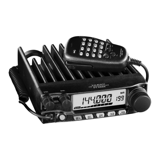
- Page 1 FM TRANSCEIVER FT-2980R/E Operating Manual...
-
Page 2: Table Of Contents
Index Introduction ............ 1 Memory Tuning ........... 34 About this manual ......... 1 Masking Memories ........34 Safety Precautions ........2 Memory Bank Operation ......35 Accessories & Options ......... 4 Home Channel Memory ......37 Supplied Accessories ........4 Memory-Only Mode ........ - Page 3 FT-2980R/E Quick Reference Guide [ VOL K [ SQL K Á Â Adjusts the audio Adjust to the point where the volume level. background noise is muted. DIAL K Ã reQuency Selects the operating Frequency. [ LOcK S À Ä Ower wItch wItch...
- Page 4 FT-2980R/E Quick Reference Guide Key Overview Press Key Briefly Press and Hold Key Locks out the switches and knobs Activates the Internet Connection (except the VOL, SQL knobs and Feature. PTT switch). Allows tuning the VFO frequency in 1-MHz steps, or tuning chan- Enters the Set (“Menu”) mode.
-
Page 5: Introduction
Congratulations on your purchase of the FT-2980R/E! Whether this is your first rig, or if Yaesu equipment is already the backbone of your station, the Yaesu organization is committed to ensuring your enjoyment of this high-performance transceiver, which should provide you with many years of satisfying operation. -
Page 6: Safety Precautions
Safety Precautions Note beforehand that the company shall not be liable for any damages suffered by the customer or third parties in using this product, or for any failures and faults that occur during the use or misuse of this product, unless otherwise provided for under the law. Type and meaning of the marks This symbol indicates the possibility of death or serious injury being inflicted on the DANGER... - Page 7 DC power connector cannot be care not to mix up the positive and negative plugged in tightly. polarities. Please contact YAESU Technical Support or This may result in fire, electric shock and the retail store where you purchased the de- equipment failure.
-
Page 8: Accessories & Options
Safety Precautions Do not stand on top of the product, and do not place heavy objects on top or insert ob- jects inside it. If not, this may result in equipment failure. Do not use a microphone other than those specified when connecting a microphone to the device. -
Page 9: Front Panel Controls & Switches
Front Panel Controls & Switches ① ② ⑪ ③ ④ ⑤ ⑥ ⑦ ⑧ ⑨ ⑩ VOL Knob This control adjusts the audio volume level. Clockwise rotation increases the volume level. SQL Knob This control is used to silence background noise on the receiver. It should be advanced clockwise just to the point where the noise is silenced (and the “... - Page 10 Front Panel Controls & Switches [ REV ( DW )] Key During split-frequency operation, such as through a repeater, this key re- verses the transmit and receive frequencies. Press and hold in this key for one second to activate the Dual Watch fea- ture, described in the Operation chapter (“PRI”...
-
Page 11: Microphone Switches
Microphone Switches PTT Switch ⑥ Press this switch to transmit, and re- lease it to receive. Keypad These 16 keys generate DTMF tones during transmission. ① ⑤ In the receive mode, these 16 keys can be used for direct frequency entry and/ ②... -
Page 12: Rear Panel Connectors
Rear Panel Connectors ③ ② ① USA/Asian version European version 13.8V DC Cable Pigtail This is the power supply connection for the transceiver. Use the supplied DC cable to connect this pigtail to the car battery or other DC power supply capable of at least 15 Amperes (continuous duty). -
Page 13: Installation
Installation This chapter describes the installation procedure for integrating the FT-2980R/E into a typical amateur radio station. It is presumed that you possess technical knowledge and conceptual understanding consistent with your status as a licensed radio amateur. Please take some extra time to make certain that the important safety and technical requirements detailed in this chapter are followed closely. -
Page 14: Antenna Consideration
Installation Antenna Consideration The FT-2980R/E is designed for 50 Ohm resistive impedance at the amateur operating frequencies. The antenna (or a 50 Ohm dummy load) should be connected whenever the transceiver is turned on, to avoid damage that could otherwise result if transmission occurs accidentally without an antenna. - Page 15 Installation Mobile Power Connections To minimize voltage drop and avoid blowing the vehicle’s fuses, connect the supplied DC power cable directly to the battery terminals. Do not attempt to defeat or bypass the DC cable’s fuse - it is there to protect you, your transceiver, and your vehicle’s electrical system.
-
Page 16: Base Station Installation
15 Amps continuously at 13.8 Volts DC. The FP-1023 (USA market only) and FP-1030A AC Power Supplies are available from your Yaesu dealer to satisfy these requirements. Other well-regulated power supplies may be used, as well, if they meet the above voltage and current specifications. -
Page 17: Basic Operation
Basic Operation Turning the Transceiver On and Off 1. To turn the transceiver on, press and hold in the PWR key for one second. When you turn on the FT-2980R/E, the current DC supply voltage is indicated on the LCD for 2 seconds. After this interval, the display will switch its normal indication of the operating frequency. -
Page 18: Frequency Navigation
Basic Operation Frequency Navigation 1 ) Tuning Dial Rotating the DIAL knob allows tuning in the pre-programmed steps. Clockwise rotation of the DIAL knob causes the FT-2980R/E to be tuned toward a higher frequency, while counter-clockwise rotation will lower the operating frequency. Press the [ MHz ( SET )] key momentarily, then rotate the DIAL knob, to change the frequency steps to 1 MHz per step. -
Page 19: Transmission
Basic Operation Transmission To transmit, simply close the PTT (Push To Talk) switch on the microphone when the frequency is clear. Hold the microphone approximately 1” (25 mm) from your mouth, and speak into the microphone in a normal voice level. When your transmission is complete, release the PTT switch;... -
Page 20: Advanced Operation
Advanced Operation Weather Broadcast Reception (USA Version) The FT-2980R/E includes a unique feature which allows reception of weather broadcasts in the 160 MHz frequency range. Ten standard Weather Broadcast channels are pre- loaded into a special memory bank. To listen to a Weather Broadcast Channel: 1. -
Page 21: Lock Feature
Advanced Operation LOCK Feature To activate the locking feature, press and hold in the [ ( L )] key for one second. The “ ” icon will appear on the LCD. To cancel locking, press and hold in the [ ( L )] key again for one second. -
Page 22: Channel Step Selection
Advanced Operation Channel Step Selection Tuning steps are factory preset to default increments which are appropriate for the country to which this radio is exported. You may have a reason to use a different step size, however, and here is the procedure for changing the channel steps: 1. -
Page 23: Repeater Operation
Repeater Operation The FT-2980R/E includes a host of convenience features which makes operation on amateur repeaters both efficient and enjoyable. This transceiver offers three methods of setting up split-frequency operation on repeaters: Manual selection of preset repeater shifts (Standard Repeater Shift); ... -
Page 24: Automatic Repeater Shift
Repeater Operation Automatic Repeater Shift The ARS (Automatic Repeater Shift) feature in this transceiver allows easy and convenient repeater operation by automatically activating the repeater shift function whenever you tune to a standard repeater subband. The ARS function is preset at the factory to conform to the standards for the country to which it is exported. -
Page 25: Ctcss/Dcs/Epcs Operation
CTCSS/DCS/EPCS Operation CTCSS Operation Many repeater systems require that a very-low-frequency audio tone be superimposed on your FM carrier in order to activate the repeater. This helps prevent false activation of the repeater by radar or spurious signals from other transmitters. This tone system, called “CTCSS”... - Page 26 CTCSS/DCS/EPCS Operation 7. When you have made your selection, press and hold in the [ MHz ( SET )] key for one second to save the new setting and exit to normal operation. 1) Your repeater may or may not re-transmit a CTCSS tone - some systems just use CTCSS to control access to the repeater, but don’t pass it along when transmitting.
-
Page 27: Dcs Operation
CTCSS/DCS/EPCS Operation DCS Operation Another form of tone access control is Digital Code Squelch, or DCS. It is a newer, more advanced tone system which generally provides more immunity from false paging than does CTCSS. The DCS Encoder/Decoder is built into your FT-2980R/E, and operation is very similar to that just described for CTCSS. -
Page 28: Tone Search Scanning
CTCSS/DCS/EPCS Operation Tone Search Scanning In operating situations where you don’t know the CTCSS tone or DCS code being used by another station or stations, you can command the radio to listen to the incoming signal and scan in search of the tone being used. Two things must be remembered in this regard: ... -
Page 29: Epcs (Enhanced Paging & Code Squelch) Operation
CTCSS/DCS/EPCS Operation EPCS (Enhanced Paging & Code Squelch) Operation The FT-2980R/E includes an Enhanced CTCSS tone encoder/decoder and a dedicated microprocessor providing paging and selective calling features. This allows you to place a call to a specific station (Paging), and to receive calls of your choice directed only to you (Code Squelch). - Page 30 CTCSS/DCS/EPCS Operation Activating the Enhanced Paging & Code Squelch System 1. Press and hold in the [ MHz ( SET )] key for one second, then rotate the DIAL knob to select “ 32 PAGER ”. 2. Press the [ MHz ( SET )] key, then rotate the DIAL knob to set this Menu item to “...
-
Page 31: Ctcss/Dcs/Epcs Bell Operation
CTCSS/DCS/EPCS Operation CTCSS/DCS/EPCS Bell Operation During CTCSS Decode, DCS, or EPCS operation, you may set up the FT-2980R/E such that a ringing “bell” sound alerts you to the fact that a call is coming in. Here is the procedure for activating the CTCSS/DCS/EPCS Bell: 1. -
Page 32: Dtmf Operation
DTMF Operation The Microphone’s 16-button keypad allows easy DTMF dialing for Autopatch, repeater control, or Internet-link access purposes. Besides numerical digits [ 0 ] through [ 9 ] , the keypad includes the [ ] and [ # ] digits, plus the [ A ] , [ B ] , [ C ] , and [ D ] tones often used for repeater control. - Page 33 DTMF Operation To transmit the memorized telephone number, use the following procedure: 1. Press and hold in the [ MHz ( SET )] key for one second, then rotate the DIAL knob to select “ 17 DT A / M ”. 2.
-
Page 34: Memory Operation
Memory Operation The FT-2980R/E provides a wide variety of memory system resources. These include: 200 “basic” memory channels, numbered “0” through “199”. A “Home” channel, providing storage and quick recall of one prime frequency. 10 sets of band-edge memories, also known as “Programmable Memory Scan” channels, labeled “L0/U0”... -
Page 35: Storing Independent Transmit Frequencies ("Odd Splits")
Memory Operation Storing Independent Transmit Frequencies (“Odd Splits”) 1. Store the receiving frequency using the method already described. 2. Tune to the desired transmit frequency, then press and hold in the [ D/MR ( MW )] key for one second. 3. -
Page 36: Memory Recall
Memory Operation Memory Recall Once you have stored the memory or memories desired, you must now switch from the “VFO” mode to the “Memory Recall” mode, so you can operate on the just-stored memory channels. 1. Press the [ D/MR ( MW )] key, repeatedly if necessary, un- til the “MR”... -
Page 37: Labeling Memories
Memory Operation Labeling Memories You may wish to append an alpha-numeric “Tag” (label) to a memory or memories, to aid in recollection of the channel’s use (such as club name, etc.). This is easily accomplished using the Set (Menu) mode. 1. -
Page 38: Memory Tuning
Memory Operation Memory Tuning Once you have recalled a particular memory channel, you may easily tune off that channel, as though you were in the VFO mode. 1. With the FT-2980R/E in the Memory Recall mode, se- lect the desired memory channel. 2. -
Page 39: Memory Bank Operation
Memory Operation Memory Bank Operation The large number of memories available in the FT-2980R/E could be difficult to utilize without some means of organizing them. Fortunately, the FT-2980R/E includes provision for dividing the memories into as many as eight Memory Banks, so you can categorize the memories in a manner convenient to you. - Page 40 Memory Operation Removing Memories from a Memory Bank 1. While operating in the Memory Bank mode, recall the memory channel to be re- moved from a Memory Bank. 2. Press and hold in the [ D/MR ( MW )] key for one second, then press the [ A/N ( LOW )] key to remove the memory channel data from the Memory Bank.
-
Page 41: Home Channel Memory
Memory Operation Home Channel Memory A convenient one-touch “Home” channel memory is available to simplify return to your most-often-used frequency. This memory does not appear in the regular memory bank, to simplify operation and speed recall of this important channel. To recall the Home channel, just press the [ D/MR ( MW )] key, repeatedly if necessary, until the “HM”... -
Page 42: Scanning
Scanning The FT-2980R/E’s scanning capability provides the operator with many convenient methods of rapid frequency navigation. Basic Scanner Operation Before activating the scanner, make sure that the Squelch is set to silence the background noise when no signal is present. Scanning is not possible while the Squelch is open (if noise or signals are being heard). -
Page 43: Scan-Resume Options
Scanning Scan-Resume Options Three scan-resume modes are available on the FT-2980R/E: In the “ BUSY ” mode, the scanner will remain halted for as long as there is carrier present on the channel; after the carrier drops at the end of the other station’s trans- mission, scanning will resume. -
Page 44: Preferential Memory Scan
Scanning Preferential Memory Scan The FT-2980R/E also allows you to set up a “Preferential Scan List” of channels which you can “flag” within the memory system. These channels are designated by a blinking “SKIP” icon when you have selected them, one by one, for the Preferential Scan List. When you initiate memory scanning, beginning on a channel with the Blinking “SKIP”... -
Page 45: Memory Bank Link Scan
Scanning Memory Bank Link Scan When the Memory Bank feature is engaged, the scanner sweeps only memory channels in the current Memory Bank. However, if the Memory Bank Link Scan feature is enabled, you may sweep the memory channels in several Memory Banks which you have selected. To enable the Memory Bank Link Scan feature: 1. -
Page 46: Priority Channel Scanning (Dual Watch)
Scanning Priority Channel Scanning (Dual Watch) The FT-2980R/E’s scanning features include a two-channel scanning capability which allows you to operate on a VFO, Memory channel, or Home channel, while periodically checking a user-defined Memory Channel for activity. If a station is received on the Memory Channel which is strong enough to open the Squelch, the scanner will pause on that station in accordance with the Scan-Resume mode set via Menu item “41 RESUME”. -
Page 47: Weather Alert Scan
Scanning Weather Alert Scan This feature allows you to check the Weather Broadcast Memory Channels for the presence of the NOAA Alert Tone while operating using VFO scan or Memory channel scan. When the Weather Alert Scan feature is engaged, the FT-2980R/E will check the Weather Broadcast Memory Channels for activity every five seconds while scanning. -
Page 48: Smart Search Operation
Smart Search Operation The Smart Search feature allows you to load frequencies automatically according to where activity is encountered by your radio. When Smart Search is engaged, the transceiver will search above and below your current frequency, storing active frequencies as it goes (without stopping on them even momentarily);... -
Page 49: Internet Connection Feature
The FT-2980R/E can be used to access a “node” (repeater or base station) which is tied into the Yaesu WIRES™ (Wide-Coverage Internet Repeater Enhancement System) network. Details may be found at the WiRES-II Web site: http://www.yaesu.com/jp/en/ wiresinfo-en/index.html. This feature may also be used to access other systems, as de- scribed below. - Page 50 Internet Connection Feature 4. Rotate the DIAL knob to select “ F ” (representing DTMF “#”: the first digit of the DTMF string). 5. Press the [ LOW ( A/N )] key momentarily to accept the first digit and move to the second digit of the DTMF string.
- Page 51 Internet Connection Feature 5. Rotate the DIAL knob while pressing the [ ] key to select the Internet Memory register number ( F0 ~ F9 ) (or Name) corresponding to the Internet link repeater to which you wish to establish an Internet link, then press the PTT switch momentarily to lock in the selected access number.
-
Page 52: Arts™ (Automatic Range Transponder System)
ARTS™ (Automatic Range Transponder System) The ARTS™ feature uses DCS signaling to inform both parties when you and another ARTS™-equipped station are within communications range. This may be particularly useful during Search-and Rescue situations, where is important to stay in contact with other members of your group. - Page 53 ARTS™ (Automatic Range Transponder System) ARTS™ Polling Time Options The ARTS™ feature may be programmed to poll every 25 seconds (default value) or 15 seconds. The default value provides maximum battery conservation, because the polling signal is sent out less frequently. To change the polling interval: 1.
- Page 54 ARTS™ (Automatic Range Transponder System) CW Identifier Setup The ARTS™ feature includes a CW identifier, as discussed previously. Every ten minutes during ARTS™ operation, the radio can be instructed to send “DE (your callsign) K”, if this feature is enabled. The callsign field may contain up to 16 characters. Here’s how to program the CW Identifier: 1.
-
Page 55: Cw Training Feature
CW Training Feature The FT-2980R/E provides a CW Training feature, which sends random Morse Code via the sidetone (heard in the speaker), so you can improve your CW proficiency. 1. Press and hold in the [ MHz ( SET )] key for one second, then rotate the DIAL knob to select “... -
Page 56: Packet Operation
Packet Operation The FT-2980R/E may be used for 1200 bps Packet operation, using most all commonly- available Terminal Node Controllers (TNCs). Connections between the transceiver and the TNC are accomplished via the front panel Microphone connector and rear panel External Speaker jack, per the diagram below. The audio level from the receiver to the TNC may be adjusted by using the VOL knob, as with voice operation. -
Page 57: Miscellaneous Settings
Miscellaneous Settings Password The FT-2980R/E provides a password feature which can minimize the chance that your transceiver could be used by an unauthorized party. When the password feature is activated, the radio will ask for the four digit password to be entered when the radio is first turned on. -
Page 58: Time-Out Timer (Tot)
Miscellaneous Settings Time-Out Timer (TOT) The “Time-Out Timer” (TOT) feature is designed to force the transceiver into the “receive” mode after a preset time period of continuous transmission (the default is 3 minutes). This feature prevents your transceiver from transmitting a “dead carrier” for a long period of time in the event that the microphone PTT switch is accidentally locked in the “TX”... -
Page 59: Busy Channel Lock-Out (Bclo)
Miscellaneous Settings Busy Channel Lock-Out (BCLO) The BCLO feature prevents the radio’s transmitter from being activated if a signal strong enough to break through the “noise” squelch is present. On a frequency where stations using different CTCSS or DCS codes may be active, BCLO prevents you from disrupting their communications accidentally (because your radio may be muted by its own Tone Decoder). -
Page 60: Programming The Key Assignments
Miscellaneous Settings Programming the Key Assignments Default FT-2980R/E key functions have been assigned to the Microphone’s [ P1 ] / [ P2 ] / [ P3 ] / [ P4 ] buttons at the factory. These may be changed by the user, if you wish to assign quick access to another function. -
Page 61: Fm Bandwidth & Tx Deviation Level
Miscellaneous Settings FM Bandwidth & TX Deviation Level You can reduce the receiver bandwidth and microphone deviation level when operating on tightly-clustered frequencies (channel spacing of 12.5 or 15 kHz). This will reduce the transmitter deviation, thus minimizing interference to other users. To configure for the narrower bandwidth, use the following procedure: 1. -
Page 62: Dcs Code Inversion
Miscellaneous Settings DCS Code Inversion The DCS system was first introduced in the commercial LMR (Land Mobile Radio) service, where it is now in widespread use. DCS is sometime referred to by its different proprietary names, such as DPL (Digital Private Line , a registered trademark of ®... -
Page 63: Reset Procedure
Reset Procedure In some instances of erratic or unpredictable operation, the cause may be corruption of data in the microprocessor (due to static electricity, etc.). If this happens, resetting of the microprocessor may restore normal operation. Note that all memories will be erased if you do a complete microprocessor reset, as described below. -
Page 64: Cloning
Cloning The FT-2980R/E includes a convenient “Clone” feature, which allows the memory and configuration data from one transceiver to be transferred to another FT-2980R/E. This can be particularly useful when configuring a number of transceivers for a public service operation. Here is the procedure for Cloning one radio’s data to another: 1. -
Page 65: Set" ( Menu ) Mode
“Set” ( Menu ) Mode The FT-2980R/E Set (Menu) mode, already described in parts of many previous chapters, is easy to activate and set. It may be used for configuration of a wide variety of transceiver parameters, some of which have not been detailed previously. Use the following procedure to activate the Set (Menu) mode: 1. - Page 66 “Set” (Menu) Mode Menu Item Function Available Values Default 20 DT SPD Setting of the DTMF Autodialer Sending Speed. 50 / 100 (ms) 50 (ms) 21 EDG.BEP Enables/Disable the Band-edge beeper while scan- ON / OFF ning. 22 INT CD Selects the Access Number (DTMF digit) for DTMF 0 - DTMF 9 / DTMF 1...
- Page 67 “Set” (Menu) Mode Menu Item Function Available Values Default 47 SKIP Selects the Memory Scan mode. SKIP / ONLY / OFF 48 SPLIT Enables/Disables the split CTCSS/DCS coding. ON / OFF 49 SQL.TYP Selects the Tone Encoder and/or Decoder mode. TONE / TSQL / DCS / RV TN / OFF 50 STEP...
-
Page 68: Menu Selection Details
“Set” (Menu) Mode Menu Selection Details 1 APO Function: Enables/Disables the Automatic Power Off feature. Available Values: 30MIN / 1HOUR / 3HOUR / 5HOUR / 8HOUR / OFF Default: OFF 2 AR BEP Function: Selects the Beep option during ARTS operation. Available Values: IN RNG / ALWAYS / OFF Default:IN RNG IN RNG: Beeps sound only when the radio first detects that you are within range. - Page 69 “Set” (Menu) Mode 10 CLK.SFT Function: Shifting of the CPU clock frequency. Available Values: ON / OFF Default: OFF This function is only used to move a spurious response “birdie”, should it fall on a de- sired frequency. 11 CW ID Function: Enables/Disables the CW identifier during ARTS Operation.
- Page 70 “Set” (Menu) Mode 17 DT A/M Function: Enables/Disables the DTMF Autodialer feature. Available Values: MANUAL / AUTO Default: MANUAL 18 DT DLY Function: Setting of the DTMF Autodialer’s TX Delay Time. Available Values: 50 / 250 / 450 / 750 / 1000 ms Default: 450 ms 19 DT SET Function: Loading of the DTMF Autodialer Memories.
- Page 71 “Set” (Menu) Mode 27 MCGAIN Function: Adjust the microphone gain level. Available Values: 1 - 9 Default: 5 28 MEM.SCN Function: Selects the Memory Scan mode. Available Values: TAG1 / TAG2 / ALL CH Default: ALL CH ALL CH: The scanner sweeps all Memory channels. TAG1: The scanner sweeps only those Memory channels with the same “first”...
- Page 72 “Set” (Menu) Mode 32 PAGER Function: Enables/Disables the Enhanced CTCSS Paging & Code Squelch function. Available Values: ON / OFF Default: OFF 33 PAG.ABK Function: Enables/Disables the Answer Back function of the Enhanced CTCSS Paging & Code Squelch function. Available Values: ON / OFF Default: OFF 34 PAG.CDR Function: Setting the Receiver Pager Code for the Enhanced CTCSS Paging &...
- Page 73 “Set” (Menu) Mode 40 PSWD Function: Programs and activates the Password feature. Available Values: ON / OFF Default: OFF 41 RESUME Function: Selects the Scan Resume mode. Available Values: BUSY / HOLD / 3SEC / 5SEC / 10SEC Default: BUSY BUSY: The scanner will hold until the signal disappears, then will resume when the carrier drops.
- Page 74 “Set” (Menu) Mode 47 SKIP Function: Selects the Memory Scan mode. Available Values: SKIP / ONLY / OFF Default: OFF SKIP: The scanner will “skip” the flagged channels during scanning. ONLY: The scanner will only scan channels that are flagged (Preferential Scan List). OFF: All memory channels will be scanned (the “flag”...
- Page 75 “Set” (Menu) Mode 53 TOT Function: Sets the Time-Out Timer. Available Values: 1MIN / 3MIN / 5MIN / 10MIN / OFF Default: 3MIN The time-out timer shuts off the transmitter after continuous transmission of the pro- grammed time. 54 TS MUT Function: Enables/Disables the receiver audio output while the Tone Search Scanner is activated.
-
Page 76: Maintenance
Maintenance The inherent quality of the solid-state components used in this transceiver will provide many years of continuous use. In the unlikely event of problems, please contact your Dealer or our repair facility. In the unlikely event that the radio fails to perform or needs servicing, please contact your Dealer. -
Page 77: Specifications
Specifications General Frequency Range: Tx 136 - 174 MHz (Asian version) 144 - 148 MHz (USA version) 144 - 146 MHz (European version) Rx 136 - 174 MHz Channel Step: 5/10/12.5/15/20/25/50/100 kHz Standard Repeater Shift: ±600 kHz Frequency Stability: Better than ±10 ppm [–4 °F to +140 °F (–20 °C to +60 °C)] Modes of Emission: F2D/F3E... -
Page 78: After-Market Services
Contact Yaesu Service Center for non-warranty repairs Repairs will be made at the user’s expense if normal functions can be maintained after the repair. Please check with the retail store or Yaesu service center for more information. Hole side up... - Page 79 1. Changes or modifications to this device not expressly approved by YAESU MUSEN could void the user’s authorization to operate this device. 2. This device complies with part 15 of the FCC Rules. Operation is subject to the following two conditions: (1) This device may not cause harmful interference, and (2) this device must accept any interference including received, interference that may cause undesired operation.
- Page 80 Copyright 2017 YAESU MUSEN CO., LTD. All rights reserved. No portion of this manual may be reproduced without the permission of YAESU MUSEN CO., LTD. YAESU MUSEN CO., LTD. Tennozu Parkside Building 2-5-8 Higashi-Shinagawa, Shinagawa-ku, Tokyo 140-0002 Japan YAESU USA 1710Y-BS 6125 Phyllis Drive, Cypress, CA 90630, U.S.A.
Need help?
Do you have a question about the FT-2980E and is the answer not in the manual?
Questions and answers