Table of Contents
Advertisement
Quick Links
TANKLESS GAS WATER HEATER
Owner's Guide
WARNING
- Do not store or use gasoline or other flammable vapors and liquids in the
vicinity of this or any other appliance.
- WHAT TO DO IF YOU SMELL GAS
• Do not try to light any appliance.
• Do not touch any electrical switch; do not use any phone in your building.
• Immediately call your gas supplier from a neighbor's phone. Follow the
gas supplier's instructions.
• If you cannot reach your gas supplier, call the fire department.
- Installation and service must be performed by a qualified installer, service
agency or the gas supplier.
CERTIFIED
Low NOx Approved
by SCAQMD
14 ng/J or 20 ppm
(Natural Gas Only)
SBA8883-1
Rev. 03/13
Models : NC1991-OD
FOR USE IN COMMERCIAL APPLICATIONS.
If the information in this manual is not followed exactly, a fire or explosion
may result causing property damage, personal injury, or death.
Thank you for purchasing this Noritz Tankless Gas Water Heater.
Before using, please:
Read this manual completely for operation instructions.
R
Completely fill out the warranty registration card (included separately) and
mail the detachable portion to Noritz America Corporation.
Keep this manual (and the remainder of the warranty registration card) where
it can be found whenever necessary.
Installation must conform with local codes, or in the absence of local codes,
the National Fuel Gas Code, ANSI Z223.1/NFPA 54.
Noritz America reserves the right to discontinue, or change at any time, the
designs and/or specifications of its products without notice.
NORITZ America Corporation
NC1991-DVC
*SBA8883*
Advertisement
Table of Contents

Related Manuals for Noritz NC1991-OD-NG


Summary of Contents for Noritz NC1991-OD-NG
- Page 1 Installation must conform with local codes, or in the absence of local codes, the National Fuel Gas Code, ANSI Z223.1/NFPA 54. Noritz America reserves the right to discontinue, or change at any time, the designs and/or specifications of its products without notice.
-
Page 2: Important Safety Information
Important Safety Information-1 To prevent damage to property and injury to the user, the icons shown below will be used to warn of varying levels of danger. Every indication is critical to the safe operation of the water heater and must be understood and observed. Potential dangers from accidents during installation and use are divided into the following four categories. - Page 3 B. BEFORE OPERATING smell all around the water heater area for If you detect abnormal combustion evidence of leaking gas. Be sure or abnormal odors, or during an to smell next to the floor because earthquake, tornado or fire: some gas is heavier than air and Be sure to do. 1. Turn off the hot water supply. will settle on the floor. 2. Turn off the power to the water heater. WHAT TO DO IF YOU SMELL GAS. 3. Turn off gas and water supply valve. • Do not try to light any 4. Call the nearest Noritz agent. appliance. • Do not touch any electrical switch; do not use any phone Explosion Hazard ; in your building. If the temperature and pressure relief • Immediately call your gas valve is dripping or leaking, have a Prohibited supplier from a neighbor’s qualified service technician replace it. phone. Follow the gas supplier’s Do not plug or remove the valve. instructions. • If you cannot reach your gas Failure to follow these instructions can result supplier, call the fire department.
- Page 4 Important Safety Information (Continued) WARNING Do not place the unit or the flue terminal Carbon Monoxide Poisoning Hazard. Do in an indoor environment by means of not install this water heater in a mobile adding walls and ceiling (Do not enclose home, recreational vehicle or on a boat. Prohibited Prohibited using corrugated sheets, etc.) Do not use combustible chemicals Flue terminal such as oil, gasoline, benzene etc. in the near the heater or the flue terminal. Prohibited Do not store or use gasoline or other Unit flammable vapors and liquids in the vicinity of this or any other appliance. Prohibited Carbon monoxide poisoning or fire may Do not place or use a spray can near occur as a result. the water heater or the flue terminal.
- Page 5 (Continued) California Proposition 65 lists chemical substances Do not touch the power known to the state to cause cancer, birth defects, cord with wet hands. death, serious illness or other reproductive harm. This product may contain such substances, Don’t touch Electric with a wet hand. Shock. be their origin from fuel combustion (gas, oil) or components of the product itself. Consult the nearest Noritz agent if the water heater location needs to The gas conversion kit shall be installed by a be changed. qualified service agency in accordance with Be sure to do. the manufacturer’s instructions and all applicable codes and requirements of the Contact a qualified service authority having jurisdiction. The information technician for any necessary in the instructions must be followed to minimize repairs, service or maintenance. the risk of fire or explosion or to prevent Don’t disassemble property damage, personal injury, or death. the equipment. The qualified service agency is responsible for the proper installation of this kit. The...
- Page 6 Important Safety Information CAUTION Do not drink water that has been inside the This unit is only approved for installation unit for an extended period of time. Do not up to 4500 ft. (1350m) above sea level. drink the first use of hot water from the For installations at higher elevations, contact Noritz unit in the morning. America for Instructions. Clean the filter on the water inlet as Do not disassemble the remote controller. frequently as required by the quality of your local water. Do not use benzene, oil or fat detergents to clean the remote controller. Keep the area around the unit clean. This may cause deformation. If boxes, weeds, cobwebs, cockroaches etc. are in Do not get the remote controller wet. the vicinity of the unit, damage or fire can result.
-
Page 7: Table Of Contents
Contents Important Safety Information ............... 2 Contents......................7 RC-9018M Operation Overview ..............8 Initial Operation .................... 10 General Parts Main Unit ....................11 Remote Controller ..................12 System Check....................14 For All Systems Clock Adjustment ..................16 Using the Water Heater ................17 Setting Hot Water Temperature..............18 Automatic Water Heater “ON” or “OFF” Operation ....... 20 Locking the Remote Controller..............22 Customizable Settings <Misc settings>..........23 For System [Rcrc] Enabling Automatic Recirculation Operation . -
Page 8: Rc-9018M Operation Overview
RC-9018M Operation Overview Basic operation It is possible to It is possible to lock [ For recirculation systems ( automatically turn remote controller It is possible to circulate hot water only the water heater operation. during preferred times of day. “ON” or “OFF”. Automatically turned "ON" Automatically turned "OFF" p.20 p.22 p.28 [When using only one water heater:] It is possible to set the remote controller to alert the user when the Pi Pi !! bathtub has reached a preset fill volume to prevent overfilling. p.30 Power Saving Mode The initial setting is set to "Powersave dsply : No-1" If you set "Powersave dsply" to "Yes" ( p.23), unnecessary power consumption by the remote The display turns off... - Page 9 User Preferences The remote controller can be customized based on the preference of the user in the following ways: The set temperature can be The clock display can be The remote controller restricted to a maximum level shown even though the power display can be turned to prevent high temperature ON/OFF button is set to "OFF". off to save power. settings from being selected. Adjusting the Maximum p.23 Power Saving Modes p.23 Output Temperature The brightness of the The remote controller can be The remote controller can be remote controller can be muted so that it does not emit a muted so that it does not emit adjusted for tone when a button is pressed. a tone when an error occurs. better visibility. Remote Controller Display Muting the p.24 p.24 p.24 Error Tone Settings Brightness Settings Remote Controller Additional Settings Draining the water heater (freeze prevention). p.25 "Draining the Water Heater" Restoring default remote controller settings. p.25 "Restoring Default Settings"...
-
Page 10: Initial Operation
Initial Operation Before the first use of your water heater, make the following preparations. 1 through 4 Follow steps Open the water supply valve. OPEN CLOSED Open a hot water fixture to confirm that water is available, and then close the fixture again. Hot water fixture Open the gas supply valve. -
Page 11: General Parts
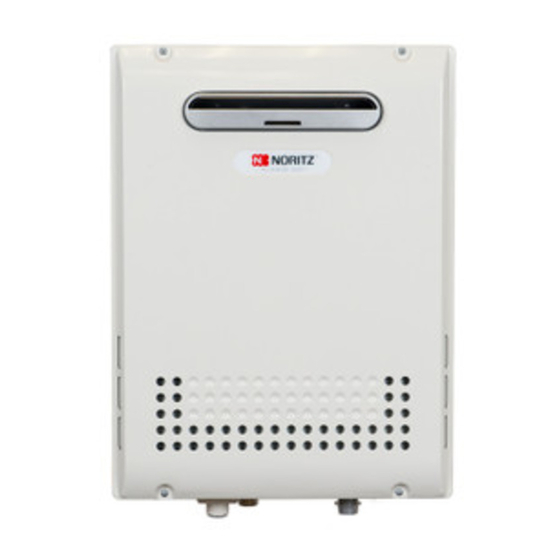
General Parts -1 Main Unit NC1991-OD (Outdoor Wall Mounted, Power Vented Model) Exhaust Vent Front Cover Air Inlet Water Drain Valve (with Water Filter) (Inside Water Inlet) Pressure Relief Valve p.36) Water Supply Valve Gas Supply Valve NC1991-DVC (Indoor Wall Mounted, Power Vent/Sealed Model) Concentric Pipe Front Cover Water Drain Valve (with Water Filter) (Inside Water Inlet) Pressure Relief Valve p.36) Water Supply Valve Gas Supply Valve * The above illustration shows an example of installation. The exact installation configuration may be slightly different. -
Page 12: Remote Controller
General Parts -2 Remote Controller (RC-9018M) The remote controller will emit a tone when a button is pressed. Alarm Off Button Prog Button / Indicator (Red) / Indicator (Red) Activates the automatic water heater power Stops the tone that is emitted “ON” or “OFF” setting as determined by the when an error occurs. ( p.41) user selected schedule. - Page 13 Screen Display * The screen display shown below is for illustration purposes only. The actual display will vary depending on how the water heater is being used. * After a button is pressed, the display will gradually become darker to prevent unnecessary power consumption by the remote controller.
-
Page 14: System Check
System Check If you press the button, you can check the status of the system (Display Screen Example [System [Rcrc] ]) Cover shown in the open position. System Displayed on System Description the Remote Controller Water heater only operation. * Water heater and recirculation operation. * During recirculation operation, hot water is always circulated in the piping to provide instant hot water when a fixture is opened. [If you set the button to "ON", is displayed. - Page 15 Depending on the configuration of your system, not all functions may be used. General System Diagram Applicable Remote * The number of water heaters, fixtures, and Controller Functions pumps will vary depending on the configuration of the hot water system. Water heater When you start using the system, cold Functions other than water in the piping must be discharged those shown on pages before receiving hot water.
-
Page 16: For All Systems
Clock Adjustment For All Systems Cover shown in the open position. Operation Screen Display Description * This adjustment can be made Press the button regardless of whether the inside the cover. button is ON/OFF. Press the button. * The time changes in 1-minute increments with each press 1) Use the buttons to o f t h e b u t t o n , a n d t h e n i n 10-minute increments if the (Ex: AM10:15) reset the clock. -
Page 17: Using The Water Heater
Using the Water Heater For All Systems is displayed, hot water will be discharged at the temperature of the storage tank. Operation Screen Display Description For systems with recirculation operation, * The indicator is lit. button is "ON". is displayed here. * The previously set hot water supply temperature is shown. [For systems with recirculation operation] * If you set the button to "ON", recirculation operation is automatically started. -
Page 18: Setting Hot Water Temperature
Setting Hot Water Temperature For All Systems * If is displayed, hot water will be discharged at the temperature of the storage tank. Cover shown in the open position. Operation Screen Display Description * The indicator is lit. button is "ON". * The previously set hot water supply temperature is shown. (Ex.: 110°F) Set the temperature using the buttons inside... - Page 19 Temperature Setting Options °F : When using °F mode: The temperature settings below are examples. The temperature setting necessary depends on the usage, the length of piping and the time of year. 100 105 110 115 120 125 130 135 140 145 150 160 170 185 Washing Shower, hot water supply, etc.
-
Page 20: Automatic Water Heater "On" Or "Off" Operation
Automatic Water Heater “ON” or “OFF” For All Systems * If you set the time to turn "ON" or "OFF" the button, the button is automatically turned "ON" or "OFF" at the set time every day by just turning the button "ON". - Page 21 Operation Hint for operation Follwing this procedure allows for automated control of water heater operation without user interaction. * The setting time shown on the display of the remote controller is for example purposes only. Ex. 1: Both "ON" and "OFF" Ex.
-
Page 22: Locking The Remote Controller
Locking the Remote Controller For All Systems By locking the remote controller, the settings cannot be accidentally changed if a button is pressed by mistake. Cover shown in the open position. Operation Screen Display Description * The operation can be locked Press and hold button regardless if the... -
Page 23: Customizable Settings
Customizable Settings <Misc settings> -1 For All Systems Adjusting the Maximum Output Display Screen Power Saving Mode Temperature. [powersave dsply] The maximum output temperature To conserve power consumption by can be limited to prevent discharging the display, it can be turned off hot water at too high of a temperature. - Page 24 Customizable Settings <Misc settings> -2 For All Systems Adjusting the brightness of the <System dependent option> Muting the remote controller. display screen when the remote Error Tone Settings. The remote controller can be muted controller is turned on. so that it does not emit a tone when The remote controller can be muted a button is pressed.
- Page 25 Draining the Water Heater. Restoring Default Settings. Refer to page 33 for details.) Select settings can be restored to the factory default conditions. See items marked with a in the “Default Settings” section ( p.47). button is "OFF". button is "OFF". ...
-
Page 26: Enabling Automatic Recirculation Operation
Enabling Automatic Recirculation Operation * To check system status. ( p.14) * When “synchro ON/OFF” is set to “Yes”, recirculation can be activated automatically. * To change “synchro ON/OFF” from “Yes” to “No”, follow the same procedure as described below. Cover shown in the open position. -
Page 27: Manually Starting Recirculation Operation
Manually Starting Recirculation Operation Recirculation operation can be manually stopped or started using this procedure. Cover shown in the open position. Operation Screen Display Description * You can set this function if the 1) Press the button button is "ON". inside the cover, Select "Recirc menu"... -
Page 28: Setting The Recirculation System Operation Timer
Setting the Recirculation System * With the recirculation operation timer set, hot water will be automatically circulated in the hot water pipes. Even with this function activated, it may take several minutes for hot water to be completely circulated through the plumbing system. Set the timer to activate the recirculation system prior to the first use of hot water to ensure hot water is instantly available. - Page 29 Operation Timer Operation Screen Display Description * Every time when you press the 1) Select "AM8:00" using button, the time changes by one hour. [To keep the current “End” time] buttons. Here Press the button without 2) Press the button to changing the "End" time, and proceed to step 5. complete the “End” time setting. <Adding Additional Time Periods> * You can set multiple operation 1) Select "Add" using time periods.
-
Page 30: Single Water Heater Only
Flow Meter Alarm Single Water Heater Only If the flow meter alarm is being used to indicate when a tub is full: • If any hot water is being used besides what is going into the tub, the alarm will sound before the tub is full. - Page 31 Operation Screen Display Description Turn on hot water. Lit during combustion If the hot water temperature has been The highest temperature set so that it does not require mixing, set the mixing valve to its highest setting. The hot water in the bathtub may become lukewarm if it is mixed with cold water at the fixture. When the bathtub fills with * Why doesn't the flow meter alarm sound even if the bathtub the preset volume of water,...
-
Page 32: Preventing Damage From Freezing
Freezing cannot be prevented when the power plug is unplugged. Do not remove the power plug from the wall outlet. Freezing will be prevented regardless of whether the operation switch is ON or OFF. * In normal operation, freezing is prevented within the device automatically unless the outside temperature without wind is below -4°F (-20°C) for NC1991-OD or -30°F (-35°C) for NC1991-DVC. * The freeze prevention heaters will not prevent the plumbing external to the unit from freezing. Protect this plumbing with insulation, heat tape or electric heaters, solenoids, or pipe covers. If there remains a freezing risk, contact the nearest Noritz agent. Take the measures below for extremely cold temperatures*. Outside temperature including wind chill factor less than -4°F (-20°C) for NC1991-OD or -30°F (-35°C) for NC1991 -DVC. This method can protect not only the heater, but also the water supply, water piping and mixing valves. 1. Turn off the power. 2. Close the gas supply valve. - Page 33 If the water heater will not be used for a long period of time, drain the water. Drain the water as follows: CAUTION To avoid burns, wait until the equipment cools down before draining the water. The appliance will remain hot after it is turned off. High Temperature Drain water into a bucket to prevent water damage. Drainage Using the Remote Controller Manual Draining Close the gas valve. (1) button is “OFF”. (2) Press the button inside the cover, Select using the buttons. (1) Turn the power on/off button “On”. Press the button. (2) Turn and leave open Hot water fixture/faucet the hot water fixtures/ The "Misc settings" screen appears.
- Page 34 Preventing Damage from Freezing-2 Turning the Unit Back On 1. Check that all drain plugs are inserted. 2. Check that all hot water fixtures/faucets are closed. 3. Follow the procedure on p.10 “Initial operation”, steps 1 through 4.
-
Page 35: Regular Maintenance
Regular Maintenance-1 Periodic Inspection CAUTION To prevent burns or scalding, turn off the power button and wait until the equipment cools before performing maintenance. Be sure to do. For dust and soot in For laundry, newspaper, Check Check the exhaust vent or timber, oil, spray cans the flue terminal. and other combustible materials. near the heater or the flue terminal. For abnormal sounds Check during operation. For abnormalities in Check external appearance, discoloration or flaws. For water leaks from the Check equipment and piping. For proper operation of Check pressure relief valve. (Ex. NC1991-OD) Periodic Maintenance Equipment Wipe the outside surface with a wet cloth, then dry the surface. Use a neutral detergent to clean any stains. Remote Controller Wipe the surface with a wet cloth. • Do not use benzene, oil or fatty detergents to clean the remote controller; deformation may occur. - Page 36 2. Open all hot water fixtures. Packing 3. With a bucket ready, remove the inlet and outlet drain plugs (about 0.2 gallon (0.8L) will drain out) 4. Take the water drain valve (with water filter) out of the inlet. (See illustration to right). 5. Clean the water drain valve (with water filter) with a brush under running water. Water drain valve 6. Replace the water drain valve (with water filter) (with water filter) and close the drain plugs. (Take care not to lose the packing.) 7. Close all hot water fixtures. 8. Open the water supply valve and check that water does not leak from the drain plugs or water Water Supply drain valve (with water filter). Valve (Ex. NC1991-OD) Optional Maintenance Isolation Valves * Isolation valves may be purchased as an accessory from Noritz. They allow for full diagnostic testing and easy flushing of the system. * The kit includes two full port isolation valves and a pressure relief valve for the hot side. Contact Noritz for more information. Hot Water Service Valve Pressure Relief Valve Cold Water Service Valve Water Intlet Drain Water Outlet (Ex. NC1991-OD)
-
Page 37: Troubleshooting
Troubleshooting-1 Initial Operation • Check for reversed plumbing or crossed pipes. Unit does not attempt to ignite when water is running. • Check the water drain valve filter. ( p.36) Unit attempts to ignite but fails • Reset unit and try again. There may be air in the gas line. • Have a professional check the gas supply pressure. Temperature Hot water is not available • Are the gas and water supply valves fully open? when a fixture is opened. • Is the water supply cut off? • Is the hot water fixture/faucet sufficiently open? • Is the gas being cut off by the gas meter? (Can other gas devices such as stoves be used?) • (For LP) Is there enough gas in the tank? (Can other gas devices such as stoves be used?) • Is the water drain valve filter clogged? ( p.36) • Is the power button turned on? No water is available when • Is the water supply cut off? a fixture is opened. • Is the heater frozen? The hot water is not the correct • Is the hot water fixture/faucet sufficiently open? temperature. Water takes time to become hot when • Have you allowed enough time for the cold water in the pipes to drain out? - Page 38 Troubleshooting-2 (Continued) • The unit will not heat the water if the flow rate is less than The water is cold when only a 0.5 gallons (2L) per minute. single fixture is open. Open the fixture more or open other fixtures so that a greater flow passes through the unit, and the unit should begin heating again. • Set water temperature at 115°F to 120°F or 48°C (118°F) to Fluctuations in hot water 50°C (122°F). This will allow you to use a higher flow of hot temperatures. water thus meeting the minimum flow requirement of 0.5 GPM (2L/min.). • Clean the water filter of any debris ( p.36) Setting temperature cannot rise. • Is the maximum temperature setting appropriate? ( p.23) Amount of Hot Water The amount of hot water at a • When hot water is demanded at other fixtures, the amount available may be reduced. The maximum flow available certain fixture is not constant. from this unit is 7.5 GPM (28.2L/min.) at a 45°F (25°C) temperature rise. • Pressure fluctuations and other plumbing conditions can cause the temperature and pressure at a fixture to be unstable, but it should stabilize after a short time. • There are some types of hot water taps that discharges large volumes of hot water at first but stabilize after time.
- Page 39 Remote Controller The power ON/OFF indicator • Has there been a power failure? does not light up. • Is the power connected properly? The water temperature changes • The temperature setting and the flow meter alarm setting after a power failure or when the may both need to be reset after a power outage. power is disconnected. The clock display shows • If the time is not displayed on the clock, either a power failure has occured or power was disconnected resulting "- : - -". in the display showing "- : - -". ( p.16) The flow meter alarm does not sound • The flow meter alarm is set to sound when hot water is continuously discharged for the set volume of water. or it sounds before the bathtub has If hot water is used for other fixtures while filling the bath been filled to the set amount. tub, the alarm will sound before the tub is full. • If mixing valves are used, or if cold water is mixed with hot water at the fixture, the tub will fill more than the setting of the flow meter alarm. The setting cannot be changed when • The remote controller is locked. While the remote controller is locked these buttons a button is pressed. cannot be used. ( p.22) [For recirculation systems] • During recirculation operation, the water heater will turn Flame symbol <...
- Page 40 A small amount of water is discharged • This is normal. When the water heater is under high pressure, a small amount of water may be discharged from the pressure relief valve. from the pressure relief valve. Water Quality Damage to the water heater as a result Total Hardness* : 200 mg/L (12 gpg) or less of poor water quality is not covered by Aluminum : 0.05 to 0.2 mg/L or less the Limited Warranty. To ensure full Chloride : 250 mg/L or less warranty coverage, treat or condition Copper : 1 mg/L or less water that exceeds the target levels Iron : 0.3 mg/L or less provided in this table. Manganese : 0.05 mg/L or less : 6.5 - 8.5 Source: EPA National Secondary Drinking Water Total Dissolved Solids : 500 mg/L or less Regulations (40 CFR Part 143.3) Zinc : 5 mg/L or less Sulfate ion : 250 mg/L or less Residual chlorine : 4 mg/L or less * Maximum limit suggested by Noritz.
- Page 41 Error Code Cause Action Check whether the gas valve is open. Press the Ignition error power button to turn the unit off, open a hot water fixture/faucet, and turn the unit back on. If the flashing number doesn't return the problem is solved. Abnormal combustion, Have a professional check the gas supply pressure. low gas supply pressure Contact the nearest Noritz agent. Abnormal combustion Contact the nearest Noritz agent. Contact Noritz America if: • Any other error code appears. • An error code is indicated again after the above actions were followed. • There are any other questions. To Stop the Error Alarm Press the button (the indicator will turn off).
-
Page 42: Follow-Up Service
Follow-up Service-1 Requesting Service First follow the instructions in the troubleshooting section ( p.37 to p.41). If the error is not corrected, contact Noritz America Technical Support at 866-766-7489. We will need to know: The Model ....(check the rating plate) *See p.4 for the location of the label Date of purchase ..(see the warranty) Details of problem ..(flashing error codes, etc., in much detail as possible) Your name, address, and telephone number Desired date of visit * A request for service may be rejected if the water heater is installed in a location where working on the unit may be dangerous. Contact a plumber. If an error code is displayed, the model name and code can be checked * If more than one water heater is installed, this procedure cannot be used. - Page 43 ● Identifying units that require service (system dependent). * If you press the button , the Press the button twice screen of step 1 is displayed. inside the cover. If you press the button , the <Screen display (Example)> screen returns to the previous screen. Warranty A warranty registration card is included separately. Be sure that the plumber, date of purchase and other necessary items are filled in. Read the content carefully, and keep the warranty card in a safe place. For repairs after the warranty period, there will be a charge on any service, and service will only be performed if the unit is deemed repairable. Period of Time for Stocking Repair Parts Noritz will stock repair and maintenance parts for this unit for the time period from the date of the original installation as follows: twelve (12) years for the heat exchanger and ten (10) years for remaining parts. Reinstallation If you want to reinstall the appliance at a different location, confirm that the gas and power supply indicated on the rating plate are available at the new location. If you are not sure, consult the local utility company.
- Page 44 Follow-up Service-2 Gas Conversion If you move to a region that uses a different type of gas or if the local gas supply is converted, replacement of the gas manifold and adjustment of the appliance will be necessary. This work must be performed by either Noritz or a qualified service agency and will be charged for even during the warranty period. The qualified installer will also be responsible for purchasing the gas conversion kit directly from the manufacturer. For more information, contact Noritz America Technical Support at 866-766-7489. WARNING The gas conversion kit shall be installed by a qualified service agency* in accordance with the manufacturer’s instructions and all applicable codes and requirements of the authority having jurisdiction. The information in the instructions must be followed to minimize the risk of fire or explosion or to prevent property damage, personal injury, or death. The qualified service agency is responsible for the proper installation of this kit. The installation is not proper and complete until the operation of the converted appliance is checked as specified in the manufacturer’s instructions supplied with the kit. * A qualified service agency is any individual, firm, corporation, or company which either in person or through a representative is engaged in and is responsible for the connection, utilization, repair or servicing of gas utilization equipment or accessories; who is experienced in such work, familiar with all precautions required,...
-
Page 45: Specifications
Specifications-1 • Specifications may be changed without prior notice. • The capacity may differ slightly, depending on the water pressure, water supply, piping conditions, and water temperature. Specifications Item Specification Model Name NC1991-OD Type Installation Outdoor Wall Mounted Air Supply/Exhaust Power Vented Ignition Direct Ignition Operating Pressure 15-150 psi Minimum Flow Rate 0.5 GPM (2 L/min.) Dimensions (Height) x (Width) x (Depth) 23.6" (600mm) x 13.8" (350mm) x 9.4" (240mm) Weight 54 lbs. Water Holding Capacity 0.2 Gallon (1.0L) Connection Sizes Water Inlet 3/4" Hot Water Outlet 3/4” Gas Inlet 3/4” Power Supply 120 VAC (60Hz) Supply Consumption NG : 65W LP : 67W Freeze Prevention 161W Materials Casing Zincified Steel Plate/Polyester Coating Flue Collar Stainless Steel... - Page 46 Specifications-2 • Specifications may be changed without prior notice. • The capacity may differ slightly, depending on the water pressure, water supply, piping conditions, and water temperature. Specifications Item Specification Model Name NC1991-DVC Type Installation Indoor Wall Mounted Air Supply/Exhaust Power Vented Ignition Direct Ignition Operating Pressure 15-150 psi Minimum Flow Rate 0.5 GPM (2 L/min.) Dimensions (Height) x (Width) x (Depth) 23.6" (600mm) x 13.8" (350mm) x 11.0" (280mm) Weight 58 lbs. Water Holding Capacity 0.2 Gallon (1.0L) Connection Sizes Water Inlet 3/4" Hot Water Outlet 3/4” Gas Inlet 3/4” Power Supply 120 VAC (60Hz) Supply Consumption NG : 80W LP : 83W Freeze Prevention 193W Materials Casing Zincified Steel Plate/Polyester Coating Flue Collar Stainless Steel...
-
Page 47: Default Settings
Default Settings Items Default setting Clock display (unset) Hot water temperature 110˚F / 40˚C Hot water volume Alarm off Customizable Settings ( P23 - 25) Default setting Maximum Output Temperature 185˚F / 85˚C "Powersave dsply" and clock display No-1 Brightness of the display screen when Normal the remote controller is turned on.
Need help?
Do you have a question about the NC1991-OD-NG and is the answer not in the manual?
Questions and answers