
Related Manuals for Fluke 712B/EN


Summary of Contents for Fluke 712B/EN
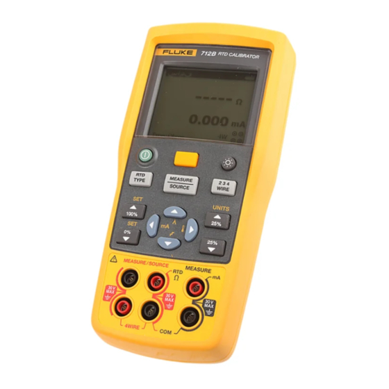
- Page 1 712B RTD Calibrator Users Manual January 2014 © 2014 Fluke Corporation. All rights reserved. Specifications are subject to change without notice. All product names are trademarks of their respective companies.
- Page 2 LIMITED WARRANTY AND LIMITATION OF LIABILITY This Fluke product will be free from defects in material and workmanship for three years from the date of purchase. This warranty does not cover fuses, disposable batteries, or damage from accident, neglect, misuse, alteration, contamination, or abnormal conditions of operation or handling.
-
Page 3: Table Of Contents
Table of Contents Title Page Introduction ........................1 How to Contact Fluke ..................... 1 Safety Information ......................3 Safe Working Practices ....................3 Standard Equipment....................... 5 Input and Output Terminals .................... 7 Keys ..........................9 Display ........................... 11 Auto Power-Off ....................... 13 Auto Backlight-Off ...................... - Page 4 712B Users Manual Set 0 % and 100 % Output Parameters ................. 22 Step and Ramp Modes ....................23 Select Step or Ramp Mode ..................23 Auto Storage of Settings ................... 23 Replace the Batteries ....................24 Maintenance ........................25 Clean the Product .....................
- Page 5 List of Tables Table Title Page Summary of Source and Measure Functions ................ 2 International Electrical Symbols .................... 4 Input/Output Terminals and Connectors ................8 Key Functions ........................10 Elements on the Display ......................12 RTD Types Accepted ......................17 Replacement Parts ........................
- Page 6 List of Figures Figure Title Page Standard Equipment ......................6 Input/Output Terminals and Connectors ................7 Keys ............................9 Elements of a Typical Display ....................11 Adjust the Contrast ........................ 14 Magnet Mounting with Hanging Strap ................... 15 Measure Temperature with an RTD ..................18 Source Temperature Signals ....................
-
Page 7: Introduction
Introduction Fluke 712B RTD Calibrator (the Product) is a handheld, battery-operated instrument that measures and sources a variety of RTDs. It also has an isolated channel to measure 4-20 mA. See Table 1. - Page 8 712B Users Manual Table 1. Summary of Source and Measure Functions Function Measure Source 0 Ω to 4000 Ω 1 Ω to 4000 Ω Resistance Pt100 Ω (385) (Resistance-Temperature Detector) Pt100 Ω (3926) Pt100 Ω (3916) Pt200 Ω (385) Pt500 Ω (385) Pt1000 Ω...
-
Page 9: Safety Information
RTD Calibrator Safety Information • Do not connect any test leads to Safety Information voltages above 30 V when used with the A Warning identifies conditions and procedures that are product, even if ratings above 30 V dangerous to the user. A Caution identifies conditions appear on the test leads. - Page 10 Product Category: With reference to the equipment types in the WEEE Directive Annex I, this product is classed as category 9 "Monitoring and Control Instrumentation" product. Do not dispose of this product as unsorted municipal waste. Go to Fluke’s website for recycling information.
-
Page 11: Standard Equipment
TL75 test leads (2 sets) • 754-8016 alligator clips (1 set) • Stackable test leads (1 set) • 4 AA alkaline batteries • Magnet Strap TPAK • 712B/714B Safety Sheet • 712B Quick Reference Guide • 712B Users Manual (available on Fluke’s website) - Page 12 712B Users Manual AC175 Alligator Clips (2 sets) 754-8016, Alligator Clips (1 set) Fluke-75X-Stackable Test Leads TL75 (1 set) Test Leads (2 sets) hqu01.eps Figure 1. Standard Equipment...
-
Page 13: Input And Output Terminals
RTD Calibrator Input and Output Terminals Input and Output Terminals Figure 2 shows the input and output terminals on the Product. Table 3 explains their use. hqu02.eps Figure 2. Input/Output Terminals and Connectors... - Page 14 712B Users Manual Table 3. Input/Output Terminals and Connectors Name Description Measure, mA terminals Input terminals for measuring current. , Source/ Measure, RTD, Ω Terminals for sourcing or measuring 2W resistance and RTDs. , terminals Measure 3W, 4W Terminals for performing 3W and 4W RTD measurements.
-
Page 15: Keys
RTD Calibrator Keys Keys The Product has keys for different purposes. Some keys have secondary functions that are available when SHIFT already shows on the display. Figure 3 shows the Product keys. Table 4 explains their use. hqu03.eps Figure 3. Keys... - Page 16 712B Users Manual Table 4. Key Functions Name Description Turns the power on or off. Shifts to secondary function when pushed before other keys (Shift mode). Turns backlight on or off. Toggles through the 2-, 3-, and 4-wire RTD measurement mode. Increments output by 25 % of span.
-
Page 17: Display
RTD Calibrator Display Display Figure 4 shows the elements of a typical display. Table 5 describes the elements. hqu19.eps Figure 4. Elements of a Typical Display... - Page 18 712B Users Manual Table 5. Elements on the Display Item No. Description 100 % of value span Source or Measure mode Selected digit that can be edited Excitation current from the measuring device under test is too low. ...
-
Page 19: Auto Power-Off
RTD Calibrator Auto Power-Off Auto Backlight-Off Auto Power-Off The Product provides an auto backlight-off function to The product provides an auto power-off function to save save power. When the auto backlight-off mode is enabled, power. When the auto power-off mode is enabled, the the backlight automatically turns off after 2 minutes of Product automatically powers off after 15 minutes of inactivity. -
Page 20: Contrast Adjustment
712B Users Manual Contrast Adjustment The Product allows you to adjust the display contrast, as shown in Figure 5. To adjust the contrast: Push until Measure shows on the display. Push to darken contrast, or to lighten contrast. hqu18.eps Figure 5. -
Page 21: Magnet Mounting And Hanging Strap
RTD Calibrator Magnet Mounting and Hanging Strap Magnet Mounting and Hanging Strap The Product has a magnet on the rear of the unit. It is removable. This magnet enables users to mount the Product on metal environment and free their hands. In addition, this Product has a hanging strap on the magnet. -
Page 22: Measure Ma Current
712B Users Manual Measure mA Current If necessary, push for Measure mode. To measure mA current, connect the Product to the Push . transmitter current terminals. Use or to select the desired type, and push Measure Temperature to confirm. - Page 23 RTD Calibrator Measure Temperature Table 6. RTD Types Accepted RTD Type Ice Point (R Material α Range (°C) 100 Ω 0.003926 Ω/°C Pt100 (3926) Platinum -200 to 630 100 Ω 0.00385 Ω/°C Pt100 (385) Platinum -200 to 800 120 Ω 0.00672 Ω/°C Ni120 (672) Nickel...
- Page 24 712B Users Manual Sensor Sensor Sensor hqu15.eps Figure 7. Measure Temperature with an RTD...
-
Page 25: Source Temperature Signals
RTD Calibrator Source Temperature Signals Source Temperature Signals The Product allows you to source temperature signals via sensor. See Figure 8. Push to switch to Source mode on temperature channel. Use the arrow keys to define the simulated temperature value. The display shows the temperature channel with a set temperature value. -
Page 26: Simulate Rtds
712B Users Manual Simulate RTDs Connect the Product to the instrument under test as shown in Figure 9. Proceed as follows to simulate an RTD: If necessary, push for Source mode. Push for the RTD display. Note Use the 2W, 3W, and 4W terminals for measurement only, not for simulation. The Product simulates a 2-wire RTD at its front panel. - Page 27 RTD Calibrator Simulate RTDs Sensor Terminal SOURCE hqu11.eps Figure 9. Connections for Simulating 3- and 4-Wire RTD...
-
Page 28: Scale Ma Channel To Temperature
712B Users Manual Scale mA Channel to Temperature Set 0 % and 100 % Output Parameters The Product provides a function to convert mA current You must set the 0 % and 100 % source values before channel reading to temperature reading. you can use the step and ramp functions. -
Page 29: Step And Ramp Modes
RTD Calibrator Step and Ramp Modes Step and Ramp Modes Auto Storage of Settings The Product automatically stores the latest settings, Select Step or Ramp Mode including the temperature unit, the linear range of mA The Product allows you to set Step and Ramp modes for converting to temperature, and sensor type. -
Page 30: Replace The Batteries
712B Users Manual Replace the Batteries Warning To prevent false readings, which could lead to possible electric shock or personal injury, replace the batteries as soon as the low battery indicator appears. Figure 10 shows you how to replace the batteries. hnh38.eps Figure 10. -
Page 31: Maintenance
To prevent damage to the plastic lens and postage paid and insured, to the nearest Service Center. case, do not use solvents or abrasive Fluke assumes no responsibility for damage in transit. cleansers. To locate an authorized service center, refer to “How to Clean the Product with a soft cloth dampened with water Contact Fluke”... -
Page 32: Replacement Parts
712B Users Manual Replacement Parts Case seal rubber 4307186 Table 7 lists the part number of each replaceable part. Case bottom assembly 4307079 Refer to Figure 11. Table 7. Replacement Parts Screw, M3, 13.5 mm, 2388382 PAN, PHILLIPS Item Description Qty. - Page 33 RTD Calibrator Replacement Parts hqu46.eps Figure 11. Replacement Parts...
-
Page 34: Specifications
712B Users Manual Specifications Specifications are based on a one year calibration cycle and apply from +18 °C to +28 °C unless stated otherwise. All specifications assume a 5 minute warmup period. DC mA Measurement Accuracy (% of Reading + Floor) Range Resolution 1 year... -
Page 35: Ohms Source
RTD Calibrator Specifications Ohms Source Accuracy Excitation Current from (% of Output + Floor) Ohms Range Measurement Device 1 year 2 year 1.0 Ω to 400.0 Ω 0.015 % + 0.1 Ω 0.03 % + 0.2 Ω 0.1 mA to 0.5 mA 1.00 Ω... -
Page 36: Rtd Input And Output
712B Users Manual RTD Input and Output Measure (°C) Source (°C) RTD Type Range Source (α) (°C) 1 year 2 year 1 year 2 year Current -200 to 100 1 mA 10Ω Pt(385) 100 to 800 1 mA -200 to 100 1 mA 50Ω... - Page 37 RTD Calibrator Specifications 0.2 °C 0.4 °C 0.4 °C -200 to 100 0.2 °C 100 Ω 1 mA Pt(3916) 0.015 %+0.18 °C 0.03 %+0.36 °C 0.015 %+0.18 °C 0.03 %+0.36 °C 100 to 630 0.2 °C 0.4 °C 0.2 °C 0.4 °C -200 to 100 100 Ω...
-
Page 38: General Specifications
712B Users Manual General Specifications Maximum voltage applied between any terminal and earth ground or between 30 V any two terminals: -10 °C to 50 °C Operating temperature -20 °C to 60 °C Storage temperature Operating altitude 2,000 meters Storage altitude 12,000 meters Non condensing 90 % (10 °C to 30 °C)
Need help?
Do you have a question about the 712B/EN and is the answer not in the manual?
Questions and answers