Table of Contents

Related Manuals for Sony VPL-PHZ12


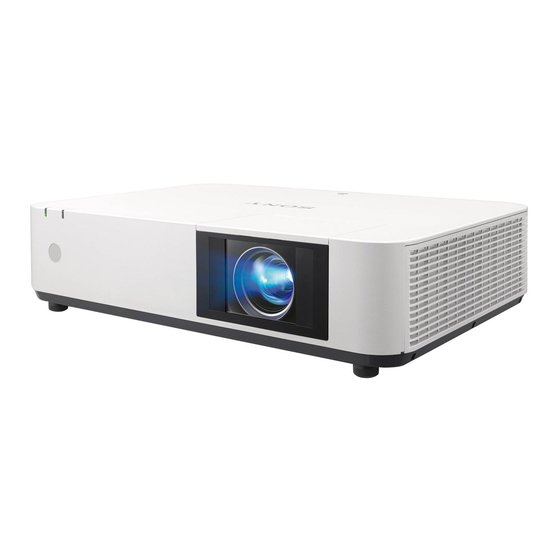
Summary of Contents for Sony VPL-PHZ12
- Page 1 5-017-555-11 (1) Data Projector Operating Instructions Before operating the unit, please read this manual and supplied Quick Reference Manual thoroughly and retain them for future reference. VPL-PHZ12 © 2020 Sony Corporation...
-
Page 2: Table Of Contents
Using the e-mail report Function ....30 Table of Contents Setting the LAN Network of the projector ............ 31 Setting the WLAN Network of the projector ............32 Overview Setting the Custom Labels for the Input Terminals of the Projector ......34 Location and Function of Controls .... - Page 3 Others Cleaning the Air Filter ........49 Updating the Software ........50 Updating the Software via the USB Memory ............ 50 Updating the Software via the Network ..50 Specifications ............ 51 Pin assignment ..........53 Acceptable Input Signals ......54 Projection Distance and Lens Shift Range ..
-
Page 4: Overview
Overview Location and Function of Controls Security lock Main Unit Connects to an optional security cable manufactured by Kensington. For details, visit Kensington’s web site. http://www.kensington.com/ Ventilation holes (intake) (page 49) Security bar Connects to a commercially available security chain or wire. -
Page 5: Terminals
Terminals Input (page 8) Output (page 13) INPUT A AUDIO (AUDIO OUT) Video: RGB/YP input terminal (RGB/YP Audio: Audio output terminal INPUT B Note Video: HDMI input terminal (HDMI) When the speaker setting is set to “Always On” and the Audio: HDMI input terminal (HDMI) light is turned off, INPUT A is enabled. -
Page 6: Remote Commander And Control Panel Keys
Press the /// keys to move the digital zoom icon Remote Commander and Control Panel Keys to the point on the image you want to enlarge. Press the D ZOOM + key or the D ZOOM – key Remote Commander repeatedly to change the enlargement ratio. - Page 7 Select “User” then press the key. The setting items appear. Press the / key to select the item then press the ENTER key. Press the / key to select the setting value. Press the ENTER key. The screen returns to the User screen. For details on each setting, see “Light Output Mode,”...
-
Page 8: Preparation
For connecting a computer with an HDMI output terminal. HDMI cable (not supplied) HDMI output terminal Computer Notes • Use HDMI-compatible equipment which has the HDMI Logo. • Use a high speed HDMI cable(s) on which the cable type logo is specified. (Sony products are recommended.) - Page 9 • The HDMI terminal of this projector is not compatible with DSD (Direct Stream Digital) Signal or CEC (Consumer Electronics Control) Signal. USB terminal (Type B) ( For connecting to a computer with a USB terminal (“Playing Video and Audio using USB Connection” (page 43)).
-
Page 10: Connecting A Video Equipment
• Use HDMI-compatible equipment which has the HDMI Logo. • Use a high speed HDMI cable(s) on which the cable type logo is specified. (Sony products are recommended.) • The HDMI terminal of this projector is not compatible with DSD (Direct Stream Digital) Signal or CEC (Consumer Electronics... -
Page 11: Connecting A Hdbaset™ Equipment
Notes for connecting this unit to the HDBaseT transmitter • Ask a professional or Sony dealer to perform wiring. If wiring is not correct, the transmission characteristics of the cable will not be achieved, and image or sound may break up or you may experience unstable performance. - Page 12 Connecting to the network equipment terminal LAN cable (straight type) (not supplied) Computer Wired connection Computer Hub, Wireless router Wireless connection HDBaseT transmitter LAN cable: STP type (CAT5e or higher, straight, not supplied) Notes When using network features, be sure to check if “LAN Setting” is set to “via HDBaseT” (page 25). ...
-
Page 13: Connecting Audio Equipment
Connecting Audio Equipment OUTPUT Input audio can be output to audio equipment such as speakers with a built-in amplifier. Audio input terminal Audio cable (stereo mini plug) (not supplied) Audio equipment Note When the Speaker Setting is set to “Always On” and the light is turned off, INPUT A is enabled. -
Page 14: Projecting/Adjusting An Image
Projecting/Adjusting an Image Projecting an Image The size of a projected image depends on the distance between the projector and screen. Install the projector so that the projected image fits the screen size. For details on projection distances and projected image sizes, see “Projection Distance and Lens Shift Range” (page 55). Video equipment Projector Wall outlet... -
Page 15: Adjusting The Focus, Size, And Position Of The Projected Image
Adjusting the Focus, Size, and Position of the Projected Image Focus Size (Zoom) Position (Lens shift) Zoom lever H lens V lens Focus lever shift dial shift dial Slide the lens shift adjustment cover as below. If you keep turning the lens shift dials, the lens shift positions are restored to the original positions. - Page 16 Use the /// keys to set the value. The higher the Adjusting the tilt of the projector with the front setting, the narrower the top of the projected image. feet (adjustable) The lower the setting, the narrower the bottom. By changing the slope of the projector with front feet (adjustable), you can adjust the position of the projected image.
-
Page 17: Turning Off The Power
adjustment, the value of the adjustment menu and the Press the RESET key to restore the projected image status of the image may not match before the adjustment before adjustment. is performed. Displaying a pattern Correcting the image twist (Corner Keystone You can display a pattern for adjusting the feature) projected image or a grid pattern with the... -
Page 18: Adjustments And Settings Using A Menu
Adjustments and Settings Using a Menu Selected items take effect immediately, except Using a MENU “Language,” “Speaker Setting,” and “Input-A Signal Sel.”, which take effect after you press the ENTER key. Note The menu displays used for the explanation below may be different depending on the model you are using. -
Page 19: Projection Setting Menu
Projection Setting Menu The Projection Setting menu is used for optimum settings appropriate to the installation location and picture adjustments for input signals. Setting items Descriptions Intelligent Setting On/Off: When you set to “On,” you can optimize the picture settings, light settings, and system cooling performance (fan rotation speed) by selecting the installation location from "Location"... - Page 20 Setting items Descriptions Expert Setting Reality Creation Adjusts the detail and noise processing of images. (Super-resolution function) On: Adjusts the settings of “Reality Creation.” Resolution: When you increase the setting value, the texture and detail of the image become sharper. Noise Filtering: When you increase the setting value, the noise (picture roughness) becomes less prominent.
-
Page 21: The Screen Menu
The Screen Menu The Screen menu is used to adjust the size, position and aspect ratio of the projected image for each input signal. Setting items Item descriptions Aspect Changes the aspect ratio of the projected image (page 22). When the computer 4:3: Displays the image to fit the maximum projected image size with an aspect ratio fixed signal is input to 4:3. - Page 22 Aspect *1: If you select “Normal,” the image is projected in the same Recommended setting value resolution as the input signal without changing the aspect Input signal and projected image ratio of the original image. *1 *2 *3 Full 1 *1 *2 *3 16:9 Full 1...
-
Page 23: The Function Menu
The Function Menu The Function menu is used for setting various functions of the projector. Setting items Item descriptions Volume The higher the value, the louder an audio volume and the lower the value, the lower the audio volume. Speaker On/Off: When set to “On,”... -
Page 24: The Operation Menu
Note *1: You will not be able to use the projector if you forget your password. If you call qualified Sony personnel because you have forgotten the password, you will be asked to verify the projector’s serial number and your identity. (This process may differ in... -
Page 25: The Connection/Power Menu
The Connection/Power Menu The Connection/Power menu is used for setting for the connections and power. Setting items Item descriptions LAN Settings IP Address Setup Auto (DHCP): The IP address is assigned automatically from the DHCP server such as a router. Manual: To specify the IP Address manually. - Page 26 Setting items Item descriptions Auto Power Saving With No Light Cutoff: The light turns off automatically and power consumption is Input reduced if no signal is input for approx. 2 minutes. The light lights again when a signal is input or any key is pressed. In Light Cutoff, the ON/STANDBY indicator lights in orange.
-
Page 27: The Installation Menu
The Installation Menu The Installation menu is used for installing the projector. Setting items Item descriptions Screen Fitting HV Keystone/ Corner Keystone: You can choose how to correct image twist. V Keystone This is displayed when “HV Keystone” is selected in “Screen Fitting.” The higher the setting, the narrower the top of the projected image. -
Page 28: The Information Menu
The Information Menu The Information menu is used to check projector status, such as total usage time of the light. Setting items Item descriptions Model Name Displays the model name. Serial No. Displays the serial number. fH/fV Displays the horizontal/vertical frequency of the current input signal. Signal Type Displays the type of the current input signal. -
Page 29: Network
Administrator: Allowed access to all pages Contact your local Sony dealer for detailed information of User: Allowed access to all pages except the Projector Station for Network Control. Setup page Set the access limitation from [Password] of the... -
Page 30: Confirming The Information Regarding The Projector
The functions of the buttons shown in the Note operation area are the same as the keys on the If you forget your password, consult with qualified Sony remote commander. personnel. The password will be reset with your permission. -
Page 31: Setting The Lan Network Of The Projector
Click on [Owner information] to enter the owner Required Authentication: Check this check box if authentication is required for information recorded in the e-mail report. sending e-mail. Requires the use of POP Authentication before sending email (POP before SMTP): Check this check box to arrange for POP authentication to be performed before sending e- mail. -
Page 32: Setting The Wlan Network Of The Projector
Click on [Network] to open the Network page. Click the [WLAN Setting] to open the WLAN Setting page. LAN Network setting area Network button Set the items for internet protocol. WLAN Setting button Obtain an IP address automatically: Automatically provides the network settings by a Enable or disable the radio wave output of USB DHCP server function, such as the router. - Page 33 Encyption Type Descriptions Encyption Type Descriptions MIX (WPA-PSK/ Sets the security method of the Open Sets the security method of the WPA2-PSK (TKIP/ access point to MIX. access point to open system AES)) (corresponding to both WPA-PSK authentication. (TKIP/AES) and WPA2-PSK (AES) WEP 64bit Sets the security method of the security methods).
-
Page 34: Setting The Custom Labels For The Input Terminals Of The Projector
The label name will be reflected on the screen when the Setting the Custom Labels for the Input input of the projector is changed. Terminals of the Projector Change the label names for the input terminals that will be displayed on the projected screen on the Setup page. - Page 35 Advertisement will also be changed. Only four alphanumeric characters can be input. The factory default setting is “SONY.” It is recommended that the community name be changed from the factory setting to avoid unnecessary access to the projector from other computers.
- Page 36 (d) Set PJ Link. -Port No.: Input the port number for the CIP protocol server. PJ Link Service setting area (f) Set the IP Control Sync. function PJ Link button IP Control Sync. IP Control Sync. setting area button Start PJ Link Service: Set PJ Link to enabled or disabled.
-
Page 37: Using The Software Update Function
You can update the software of the projector via the network. The update files can be downloaded from the following Sony website. For details, see “Updating the Software” (page 50). Note You can update the software via a network when Power status is in STANDBY. -
Page 38: Presentation Function Via Network
For a wireless connection, see “LAN terminal” (page 9) updates of Projector Station for Network or “USB terminal (Type A) ( )” (page 9). Also check Presentation, visit Sony’s web site: “WLAN Settings” (page 25). https://www.sony.co.uk/pro/product/projectors- installation/vpl-phz10/support/#support Turn on the projector. - Page 39 For Windows displayed while the computer is trying to connect. Input the password to connect. To prevent Connection guidance window information leaks, the wireless password is not displayed on the projected screen. For Windows Network Presentation LAN mode Select the connection method. Refer to the network information on the projected screen of the projector and select “LAN Mode”...
-
Page 40: Connection Settings
Items Functions Connection Settings Stop projecting an image (screen turns black). Item Item descriptions Change the application settings. IP Address Input the IP Address. List the IP addresses of the Disconnect from the projector. projectors on the network and IP addresses of projectors connected Select a projection method then start so far, as candidates. -
Page 41: Option Format
IP address:192.168.1.187 Option format Connection CODE: On For Windows Command format For LAN Mode C:\Program Files (x86)\Sony\Projector Station for Network Presentation\Network Presentation.exe - - connect [IP address]:[CODE]:[Display Setting] connect 192.168.1.187:on:1 For AP Mode - wifi [SSID]:[Wireless password]:[CODE]:[Display Setting] For Mac... -
Page 42: Station For Network Presentation
Close all running applications. Start the Projector Station for Network Presentation. For Windows Open the downloaded file. Double-click the shortcut icon of Projector Station for For Windows Network Presentation that is created in the folder in which the application is installed. Double-click the For Mac “PJS_NetworkPresentationP_XXX.exe”... -
Page 43: Playing Video And Audio Using Usb Connection
Playing Video and Audio using USB Connection Using the Controller Playing Video and Audio using USB Connection For Windows You can also play video and audio simply by connecting the projector and computer with a USB A-B cable (not supplied). For Mac Playing video and audio using USB connection requires to start USB Display. -
Page 44: Error Handling
Error Handling Indicators You can check the projector status or abnormality by checking the lighting/flashing status of the ON/ STANDBY indicator and WARNING indicator on the front. If the indicators flash in red, address the problem in accordance with “Warning indicators and remedies” (page 44). ON/STANDBY WARNING indicator... - Page 45 If the indicators flash in a manner other than described above, unplug the AC power cord and make sure the ON/STANDBY indicator turns off, then plug the AC power cord into the wall outlet and turn on the projector. If the problem still persists, consult with qualified Sony personnel.
-
Page 46: Messages List
Messages List When any of the messages listed below appears on the projected image, address the problem in accordance with the table below. Messages Meaning/Remedy Page Clean the filter. Temperature in the projector has increased. 4, 49 Projector temperature is high. As a countermeasure against use at an altitude of 1,500 m or higher, Switching to High Altitude Mode. -
Page 47: Troubleshooting
Troubleshooting Before asking to have the projector repaired, try to diagnose the problem, following the instructions below. Symptoms Remedy Page The power is not turned on. Check if the AC power cord is firmly connected. – When the “Control Key Lock” is set to “On,” you cannot turn on the projector using the /... - Page 48 Symptoms Remedy Page The image is dark/too bright. The settings for “Brightness,” “Contrast,” and “Light Output Mode” affect brightness of the image. Check if the value is appropriate. “With Static Signal” is set to “On.” When video signal is not input, the light is dimmed to reduce power consumption.
-
Page 49: Cleaning The Air Filter
If the dust cannot be removed from the air filter even after cleaning, replace the air filter with a new one. For details on a new air filter, consult with qualified Sony personnel. Caution If you keep using the projector even after the message is displayed, dust may accumulate, Loosen the screws (six) on the air filter. -
Page 50: Updating The Software
The update files can be downloaded from the Sony website. For details, refer to the following website. https://pro.sony.com https://www.sony.jp/vpl/ (Access from Japan) Updating the Software via the Network To update the software of the unit via the network, connect the computer to the LAN that the projector is connected to. -
Page 51: Specifications
Specifications Items Descriptions Projection system 3 LCD system Display device Effective display 0.76-inch (19.3 mm), 3 plate, Aspect ratio 16:10 size Effective picture 6,912,000 pixels (1,920 × 1,200 pixels, 3 plate panels) elements Projection lens Focus Manual Zoom Manual (1.45 times) Light source Laser diode Projected image... - Page 52 *2: Information on accessories in this manual is current as of April 2020. *3: Not all optional accessories are available in all countries and area. Please check with your local Sony Authorized Dealer. Design and specifications of the unit, including the optional accessories, are subject to change without...
-
Page 53: Pin Assignment
USB terminal (Type A, female) Pin assignment HDMI terminal (HDMI, female) (4.4 - 5.25 V) Data– Data+ T.M.D.S. Data2+ T.M.D.S. Clock Shield Ground T.M.D.S. Data2 Shield T.M.D.S. Clock – T.M.D.S. Data2 – N.C. T.M.D.S. Data1+ RESERVED (N.C.) USB terminal (Type B, female) T.M.D.S. -
Page 54: Acceptable Input Signals
Video signal Acceptable Input Signals Input terminal Computer signal INPUT B/ Signal fV[Hz] VIDEO INPUT A INPUT C/ Input terminal INPUT D fH[kHz]/ Resolution fV[Hz] RGB/YP HDMI NTSC – – 640 × 350 31.5/70 PAL/SECAM – – ... -
Page 55: Projection Distance And Lens Shift Range
Projection Distance and Lens Shift Range The following describes the projection distance and height from lens center to bottom of screen by each projected screen size. The projection distance is the distance between the front of the lens and the surface of the projected image. - Page 56 Projection distance/Projection distance formula Projection distance Unit: m (inches) Projected image size Height H from lens center to bottom of screen Projection Distance L Minimum Projection Maximum Projection Diagonal Width × Height Distance L Distance L 80 inch (2.03m) 1.72 × 1.08 (68 × 42) 2.18 - 3.23 (86 - 127) -0.01 (0) -0.01 (0)
- Page 57 [%] = 5.6 - 0.560 × (HS [%] or HS [%]) [%] = 29.4 - 2.940 × (HS [%] or HS [%]) [%] = HS [%] = 10 - 1.786 × (VS [%]) [%] = HS [%] = 10 - 0.340 × (VS [%]) = 5.6 [%] = 29.4 [%]...
-
Page 58: Dimensions
Dimensions Front Center of the lens Unit: mm (inches) 510 (20 146.4 (5 Center of the lens Unit: mm (inches) - Page 59 Bottom 319.3 (12 102.7 (4 Center of 170.1 (6 0.8 ( the lens Ø 25 ( 88.6 (3 Ø 25 ( 7.1 ( Holes for ceiling mount (M4, Depth 19.2 19.2 45.3 57.4 108.6 (4 Unit: mm (inches) * Specifications of ceiling mount holes Insert nut (M4) Screw hole Unit...
-
Page 60: About Trademarks
In this manual, ™ and ® marks are not specified. any images, photographs, animation, video, audio, music, text and “applets” incorporated into the SOFTWARE) is owned by SONY or one or more of the THIRD-PARTY SUPPLIERS. GRANT OF LICENSE... - Page 61 SOFTWARE may be provided collectively referred to as “SONY”) SHALL NOT BE LIABLE FOR ANY by third parties over which SONY has no control. USE OF THE CONTENT INCIDENTAL OR CONSEQUENTIAL DAMAGES FOR BREACH OF ANY SERVICE REQUIRES AN INTERNET CONNECTION.
- Page 62 TERMINATION that such services are governed by the privacy policies of SONY or such third party. By using any such services, you agree that you have Without prejudice to any of its other rights, SONY may terminate this reviewed the privacy policies applicable to such services and consent to EULA if you fail to comply with any of its terms.
- Page 63 Sony Corporation...
Need help?
Do you have a question about the VPL-PHZ12 and is the answer not in the manual?
Questions and answers