Table of Contents
Advertisement
Quick Links
Integrated, Self-Powered—Self-Processed, Industrial Systems
User Manual
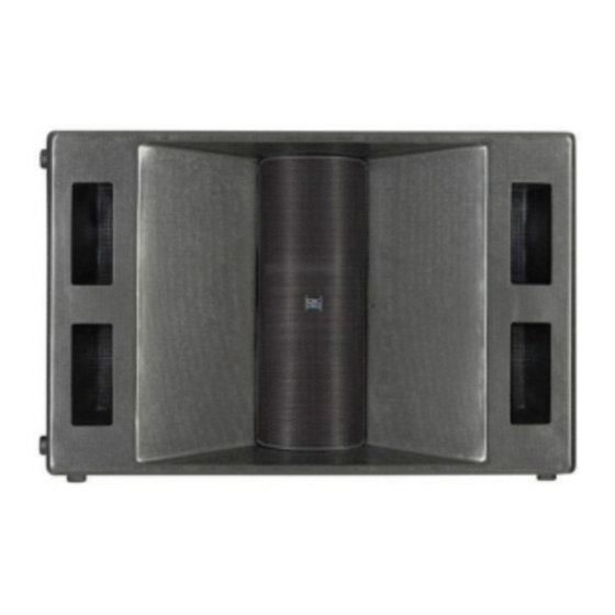
ISIS 215SB
2 x 15" Weather-Resistant Subwoofer Cabinet with Speakon™ Input Connector
ISIS 215PCM
3000 Watt Powered Subwoofer and 3600 Watt, 2-channel "Top Box" amplifier,
Computer Configurable DSP for each Amplifier, Integral Wheels and Handles.
*TD-000105-00*
1
TD-000105-00 rev.B
Advertisement
Table of Contents

Related Manuals for QSC ISIS 215PCM


Summary of Contents for QSC ISIS 215PCM
- Page 1 Integrated, Self-Powered—Self-Processed, Industrial Systems User Manual ISIS 215SB 2 x 15” Weather-Resistant Subwoofer Cabinet with Speakon™ Input Connector ISIS 215PCM 3000 Watt Powered Subwoofer and 3600 Watt, 2-channel “Top Box” amplifier, Computer Configurable DSP for each Amplifier, Integral Wheels and Handles. *TD-000105-00*...
- Page 2 6- Clean only with a dry cloth. 7- Do not block any ventilation openings. Install in accordance with QSC Audio Product’s instructions. 8- Do not install near any heat sources such as radiators, heat registers, stoves, or other apparatus (including amplifiers) that produce heat.
-
Page 3: Table Of Contents
Configuring the Processors (examples of Signal Manager software)..25 TROUBLESHOOTING...................28 SPECIFICATIONS 215SB Dimensions..................31 215SB Acoustic Performance..............32 215SB Specifications...................33 215PCM Dimensions..................34 215PCM Specifications.................35 215PCM Power Amplifier‘s Specifications............36 215PCM Digital Signal Processor’s Specifications........37 APPENDIX Contact Closure Wiring...................38 RS-232 Pinout....................39 WARRANTY INFORMATION .....................40 HOW TO CONTACT QSC AUDIO PRODUCTS ............40... -
Page 4: General Overview
DSP-3 Digital Signal Processors with 24-bit, 48 kHz. convertors. Both processors have eight user- configurable and -selectable presets. An RS-232 connection to a PC running the provided QSC Signal Manager Software enables system tuning and configuration. - Page 5 INTRODUCTION- General Overview 215PCM Front A 16” length of “L-track” flying hardware is featured on all four corners of the cabinet. Pole cups are featured for either cabinet orientation. One, shown, on the shorter side, and two on the longer. 215PCM Rear Rubber feet are featured on the bottom of the cabinet, as viewed,...
-
Page 6: Technical Overview
93 dB. All that is required is configuring the Processors with the The amplifiers are modified QSC Powerlight2 models. They desired signal chain before use. feature PowerWave™ high frequency switching power supplies for maximum performance and minimum weight. -
Page 7: Block Diagram
INTRODUCTION- Block Diagram... -
Page 8: Unpacking
Care is required in the control panel area on the rear of the cabinet. Be sure not to damage any switches or connectors. The QSC shipping box should contain: 1- The 215PCM system or 215SB cabinet 2- This Owner’s Manual... -
Page 9: Where Do I Start
WHERE DO I START? 215PCM Powered Core Module Users- Install the Signal Manager software on the PC that will be used to configure the 215PCMs processors. See page 20. Put the 215PCM in a location that: • ..is close enough to the PC to connect the serial cable. •..has 120V, 30A service to power the 215PCM. -
Page 10: Amplifier Gain Controls
This may not be the expected, desired result and could damage your speakers or hearing. For this reason, QSC recom- mends the initial “learning” sessions with the 215PCM be carried out with the amplifier Gain controls set at their minimum useful settings. -
Page 11: Ac Power
CONNECTIONS- AC Power AC Power Connection The 215PCM requires a 120 Volt, 30 Amp connection to the AC mains. The power connectors used are to be NEMA L5-30, or equivalent. The serial number plate is imprinted with the operating voltage informa- tion. -
Page 12: Processor Rs-232
CONNECTIONS- RS-232 Processor Configuration Connection RS-232 Connection (215PCM only) Each Processor has a 9-pin “D-sub” connector labeled RS-232. The RS-232 connection is used to configure the Processor by connecting to the PC’s COM port. Important points: – The 215PCM must be ON (powered up) in order to configure the Processors. –... -
Page 13: Mode Switch
CONNECTIONS- Mode Switch and Signal Routing MODE SWITCH (215PCM only) The position of the Mode Switch determines how the input signals are routed. Select your operating mode before making connections. If you are using the DataPorts for audio input, the Mode Switch has no effect. Refer to the diagram, below. COMBINATION MODE–... -
Page 14: Xlr Audio Inputs
CONNECTIONS- Audio Connections: XLR Inputs Audio Connections Audio inputs can be connected to the XLR inputs OR the DataPort connections (QSControl users). This section provides information on using the XLR Inputs, For DataPort information see page 17. XLR Inputs The position of the Mode Switch determines how the input signals are routed. - Page 15 CONNECTIONS- XLR Connection Recommendations and Pinouts XLR Connections The XLR inputs are electronically balanced. To maintain the benefits of balanced, pro-audio connections, make all connections to the 215PCM using balanced, high-quality cable and connectors. If balanced inputs are not available, use a unbalanced-to-balanced converter, such as a “DI” box or proper audio transformer. Unbalanced connections are prone to noise and interference pickup as well as ground-loop induced hum.
-
Page 16: Post-Processor Outputs
CH1 OUTPUT receptacle. The Subwoofer Processor CH2 OUTPUT is not normally used. QSC recommends the use of balanced audio connections exclusively. We discourage the use of unbalanced connections as they are more prone to common-mode noise pickup and ground loop hum. -
Page 17: Dataports
Use only QSC Audio DataPort Cables for DataPort connections. They provide individually shielded audio pairs for the best possible audio performance. Computer VGA cables are similar, but can degrade your audio quality. QSC DataPort cables are available from QSC Technical Services Department. -
Page 18: Outputs
CONNECTIONS- Output to Top Boxes (Speakons™) Output to Top Boxes At the right side of the rear panel are the output connections to the top box speakers. Note the color coding scheme of the text labels for each Speakon connector. The color coding corresponds with the colors of the Mode Switch labels (Combination Mode or Discrete Mode). -
Page 19: Cooling Air Intake And Exhaust Vents
Do not install near any heat sources such as radiators, heat registers, stoves, or other apparatus that product heat. Cooling air is pulled into the center air intake vent by The 215PCM contains two forced-air cooled QSC both amplifiers. The air is pulled through each amp and Powerlight 2-series amplifiers. They are mounted exhausts from each end of the rear panel. -
Page 20: Ac Power Switch And Led Indicators
USE- AC Power Switch and LED Indicators AC Power Switch Above and to the right of the AC entry connector is the Power switch. The switch is labeled POWER ON, above it. To turn the power on: Press in on the upper portion of the rocker switch. -
Page 21: Important User Warning Regarding Power Levels
USE- LED Indicators (continued) and Important User Caution LED Indicators (continued) NOTE! If both PWR indicator LED’s fail to illuminate after turning the power to the 215PCM on, verify the AC power is working and is properly connected. If this fails to correct the problem, disconnect the DataPort connections (if any) and retry. -
Page 22: System Requirements And Software Installation
1. Insert the QSC Signal Manager CD into your drive (typically drive “D:”). If your computer has AUTORUN enabled, the installation will start automatically after several seconds. If it does not, then proceed to step 2, below. Otherwise, skip to step 3. -
Page 23: General Guidelines For Freely-Configurable Dsp
PROCESSOR USE: General Guidelines and Preset Description IMPORTANT! Please read before operating this Digital Signal Processor with your audio system. General Use Guidelines for Freely-Configurable DSP As a general rule, DO NOT CREATE SIGNAL LOOPS! Do not This is a professional level DSP product that allows the user mix the output of a DSP object back into its own input! to produce virtually unlimited signal processor variations There is nothing useful to achieve by doing this, you will... -
Page 24: Saving Presets
You will need to configure the preset memories with signal chains that meet the precise requirements of your sound system using QSC’s Signal Manager software. For help creating configurations, refer to the software’s on-line Help system for detailed information. -
Page 25: Configuring The Processors (Examples Of Signal Manager Software)
Processor Use: Configuring the Processors (Discrete 2.1) NOTE! The factory setting for all eight Preset memories is wire-through. Signals are passed from input to output without any processing. Each Processor must be config- ured as desired by the user. You may select configurations from the sample files (*.cfg) within Signal Manager or create your own. - Page 26 Processor Use: Configuring the Processors (Discrete 2.1 continued) Example 1- Discrete 2.1 (continued) The Subwoofer Processor is next. In Discrete Mode, the Subwoofer Processor’s input signal comes from the Input 3 XLR. Input 3 is routed to the Subwoofer Processor’s IN1 block (see example, below). The IN2 block is not placed when operating in Discrete Mode.
- Page 27 Processor Use: Configuring the Processors (3-way Mono Stack) Example 2- Active 3-way Mono Stack In a 3-way configuration, the Top Box amplifier’s two channels are used for low- and high-frequencies and the subwoofer handles bass. The Processors perform the required crossover and time delay functions. This Top Box configuration has time delays included in the DSP chain to align the impulse response of the audio.
-
Page 28: Troubleshooting
• Check each end of the power cord. The twist-lock connectors need to be fully inserted and twist-locked into place. • If using the DataPort inputs and QSC amplifier network control applications, the amplifier could be in STANDBY mode. Check with the system operator to place the amplifiers in POWER ON mode. If required, you can check this by temporarily disconnecting the DataPort cables to each Processor;... - Page 29 - Remember, all you need to do is switch the COM Port setting and then restart Signal Manager. • Consider upgrading to QSC’s amplifier network products. With QSControl, the Processor’s DSP is set up using the DataPort connections. No RS-232 connections are required and amplifier operating status can be monitored and logged.
- Page 30 The 215PCM supports two channels of amplification for Top Boxes. • QSC 8 ohm top boxes have dual-, feed-through Speakons that allow 1 or 2 additional top boxes to be daisy- chained.
-
Page 31: 215Sb Dimensions
Specifications- ISIS 215SB Dimensions SPECIFICATIONS SUBJECT TO CHANGE WITHOUT NOTICE... -
Page 32: 215Sb Acoustic Performance
Specifications- ISIS 215SB Acoustic Performance SPECIFICATIONS SUBJECT TO CHANGE WITHOUT NOTICE... -
Page 33: 215Sb Specifications
4- Maximum input power tested in accordance with AES and/or IEC recommendations, 35- 100 Hertz band limiting, 6 dB signal crest factor. 5- QSC DSP configurations available at http://www.qscaudio.com. Parameters for alternative processing hardware available upon request. SPECIFICATIONS SUBJECT TO CHANGE WITHOUT NOTICE... -
Page 34: 215Pcm Dimensions
Specifications- ISIS 215PCM Self-Powered Dimensions SPECIFICATIONS SUBJECT TO CHANGE WITHOUT NOTICE... -
Page 35: 215Pcm Specifications
215 PCM: Comprised of the 215SB Subwoofer Cabinet with a “backpack” containing two QSC DSP-3 24-bit Signal Processors, 1 ruggedized QSC PL230 3000 Watt amplifier and 1 ruggedized QSC PL236 3600 Watt amplifier. All interconnections for the audio signals and AC power are complete inside the backpack. -
Page 36: 215Pcm Power Amplifier's Specifications
Specifications- ISIS 215PCM Amplifiers Amplifier Specifications Output Power in watts Subwoofer Amplifier (PL230 type) 4 Ohms, 1 kHz, 1% THD 3000 Watts Top Box Amplifier (PL236 type) FTC: 8 Ohms per channel (20- 20 kHz., 0.03% THD) 725 Watts 4 Ohms per channel (20- 20 kHz., 0.05% THD) -
Page 37: 215Pcm Digital Signal Processor's Specifications
(applicable only to users employing QSC System Manager) System Interface Compatibility QSC DataPort amplifier network monitors Cable QSC DPC-X DataPort cable, male-male (various lengths are available , contact QSC’s Technical Services Department) DataPorts Used 2 (1 per Processor) Amplifier status monitor features... -
Page 38: Contact Closure Wiring
APPENDIX- Contact Closure Wiring Details Contact Closure Feature The contact closure feature is used to trigger gain changes All switched gain objects in a DSP configu- in the DSP. Any configuration that uses one or more ration will be triggered by the one contact switched gain objects (see Signal Manager software Help closure. -
Page 39: Rs-232 Pinout
APPENDIX- RS-232 Pinout and Pin #9 Usage Note RS-232 Pinout: The diagram below shows the pin assignments for the female RS-232 connector on the DSP-3 Processors featured in the 215PCM. Signal Description Contact Closure *Note! Pin 9 is used for contact closure input. This pin is not normally used by RS-232 devices. -
Page 40: Warranty Information
(USA only; other countries, see your dealer or distributor) Disclaimer QSC Audio Products, Inc. is not liable for any damage to amplifiers, or any other equipment that is caused by negligence or improper installation and/or use of this speaker product. - Page 42 QSC Audio Products, Inc. 1675 MacArthur Boulevard Costa Mesa, California 92626 USA “QSC” and the QSC logo are registered with the U.S. Patent and Trademark Office. ©2001 QSC Audio Products, Inc.
Need help?
Do you have a question about the ISIS 215PCM and is the answer not in the manual?
Questions and answers