Table of Contents
Advertisement
Quick Links
Model Information
Index
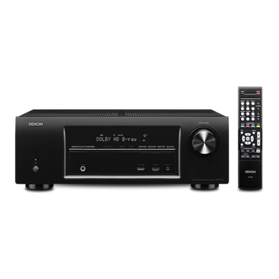
Front Panel
Rear Panel
Remote Control
Warranty
Reset Procedure
Accessories
Protection History
Display Mode
Upgrades/Updates
Product Specifications
I/R Codes
NOTE:
This edition is missing the FAQ's content (pages 12 and 13) .................................................................9/14/2015
This edition is missing the link to the IR Codes.....................................................................................9/14/2015
Model Information
INTEGRATED NETWORK AV RECEIVER
This function is
not available on
this model
MODEL:
AVR-1513
1
MI091415E3-1
Advertisement
Table of Contents

Related Manuals for D+M Group AVR-1513


Summary of Contents for D+M Group AVR-1513
- Page 1 MODEL: AVR-1513 Model Information Index Model Information Front Panel INTEGRATED NETWORK AV RECEIVER Rear Panel Remote Control Warranty Reset Procedure Accessories Protection History This function is not available on Display Mode this model Upgrades/Updates Product Specifications I/R Codes NOTE: This edition is missing the FAQ’s content (pages 12 and 13) ………………………………………………………..9/14/2015 This edition is missing the link to the IR Codes………………………………………………………………………..9/14/2015...
-
Page 2: Front Panel (1 Of 2)
Front Panel (1 of 2) Power operation button (O) Headphones jack (PHONES) Turn power to this unit on and off (standby). When the headphones are plugged into this jack, audio will no longer be output from the connected speakers. ... -
Page 3: Front Panel (2 Of 2)
Front Panel (2 of 2) DIMMER button MASTER VOLUME control knob This adjusts the volume level. Each press of this switches the brightness of the display. Master volume indicator STATUS button Display Each press of this switches the status information that is shown on the This displays various pieces of information. - Page 4 Display Tuner reception mode indicators Information display These light according to the reception conditions when the input The input source name, sound mode, setting values and other source is set to “FM”. information are displayed here. STEREO : In FM mode, this lights up when receiving analog stereo ...
- Page 5 Digital audio connectors (DIGITAL AUDIO) FM/AM antenna terminals (ANTENNA) Used to connect devices equipped with digital audio connectors. Used to connect FM and AM antennas. Subwoofer connectors (SUBWOOFER) Speaker terminals (SPEAKERS) Used to connect a subwoofer with a built-in amplifier. Used to connect speakers.
-
Page 6: Remote Control (1 Of 2)
Remote Control (1 of 2) POWER button (X) QUICK SELECT buttons (1 – 4) Input source select buttons Channel level button (CH LEVEL) SLEEP button Information button (INFO) Cursor buttons () ENTER button ... -
Page 7: Remote Control (2 Of 2)
Remote Control (2 of 2) MEMORY button MODE button SHIFT button Tuning buttons (TUNE +, –) CHANNEL buttons (+, –) DIMMER button AUDIO button VOLUME buttons (df) SETUP button TONE button ... -
Page 8: Denon Limited Warranty (1 Of 2)
DENON LIMITED WARRANTY (1 of 2) This warranty will be honored only in the U.S.A. Length of Non-Transferable Warranty This warranty on your DENON product which is distributed and warranted by DENON ELECTRONICS (USA), LLC remains in effect for the following periods from the date of the original consumer purchase from an AUTHORIZED DENON ELECTRONICS (USA), LLC DEALER. - Page 9 Warranty (2 of 2) What is Covered Except as specified below, this Warranty covers all defects in material and workmanship in this product occurring during the above warranty periods. The following are not covered by the Warranty: (1) Any product which is not distributed in the U.S.A. by DENON ELECTRONICS (USA), LLC. (2) Any product which is not purchased in the U.S.A.
- Page 10 Reset Power/Standby button Reset procedure: With the power off, press and hold the “SOURCE SELECT ” button, the “SOURCE SELECT ” button, and the “POWER” button simultaneously on the AVR for a few seconds until the display starts flashing at intervals of about 1 second. “SOURCE SELECT ”...
- Page 11 Accessories Sound Remote Control Sound Calibration (RC1170) Calibration Microphone Microphone Stand (ACM1HB) 30701010100AD AM Loop FM Indoor Power Cord) Antenna Antenna 963116100070S 8.99 90M-ZA000230R $5.99 Safety CD ROM Instructions Owner’s Manual Warranty Notes on Radio Quick Start (For North Guide America Only) HOME FAQs...
- Page 12 FAQ’s ( 1 of ?) HOME ACCESSORIES FAQ’s 2...
- Page 13 FAQ’s (2 of ?) HOME FAQ’s 1 UPGRADE...
- Page 14 Upgrades/Updates No update available for this unit HOME FQA’s 2 SPECIFICATIONS AUDIO – VIDEO...
-
Page 15: Specifications - Audio Section - Video Section
Specifications – Audio Section – Video Section Audio section 75 W + 75 W (8 Ω/ohms, 20 Hz – 20 kHz with 0.08 % T.H.D.) Front 110 W + 110 W (6 Ω/ohms, 1 kHz with 0.7 % T.H.D.) 75 W (8 Ω/ohms, 20 Hz – 20 kHz with 0.08 % T.H.D.) Rated output Center 110 W (6 Ω/ohms, 1 kHz with 0.7 % T.H.D.) -
Page 16: Specifications - Tuner Section, General Section
Specifications - Tuner Section, General Section Tuner section Note: µV at 75 Ω/ohms, 0 dBf = 1x10 520 kHz – 1710 kHz Reception frequency range 87.5 MHz - 107.9 MHz 18 μV Effective sensitivity 1.2 µV (12.8 dBf) 50 dB sensitivity MONO ―... -
Page 17: Specifications - Dimensions, Weight
Specifications – Dimensions, Weight Dimensions section (Unit : inch/mm) Weight: 17 lbs 3.1 oz(7.8 kg) HOME SPECIFICATIONS TUNER SPECIFICATIONS - - GENERAL AUDIO... - Page 18 The End NOTE: This edition is missing the FAQ’s content (pages 12 and 13) ………………………………………………………..9/14/2015 This edition is missing the link to the IR Codes………………………………………………………………………..9/14/2015 HOME...
Need help?
Do you have a question about the AVR-1513 and is the answer not in the manual?
Questions and answers