Table of Contents
Advertisement
Quick Links
Model Information
Index
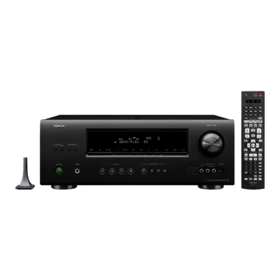
Front Panel
Rear Panel
Remote Control
Warranty
Reset Procedure
Accessories
Protection History
Display Mode
Upgrades/Updates
Product Specifications
I/R Codes
NOTE:
This edition is missing the FAQ's content (pages 12 and 13) ................................................................11/16/2016
This edition is missing the link to the IR Codes...................................................................................11/16/2016
MODEL:
Model Information
INTEGRATED NETWORK AV RECEIVER
AVR-1612
1
MI093015E3-1
Advertisement
Table of Contents

Related Manuals for D+M Group AVR-1612


Summary of Contents for D+M Group AVR-1612
- Page 1 MODEL: AVR-1612 Model Information Index Model Information Front Panel INTEGRATED NETWORK AV RECEIVER Rear Panel Remote Control Warranty Reset Procedure Accessories Protection History Display Mode Upgrades/Updates Product Specifications I/R Codes NOTE: This edition is missing the FAQ’s content (pages 12 and 13) ……………………………………………………….11/16/2016 This edition is missing the link to the IR Codes…………………………………………………….………………….11/16/2016...
-
Page 2: Front Panel
Front Panel Power operation button PORTABLE IN jack (ON/STANDBY) Remote control sensor Turns power to this unit on and off (standby). V.AUX INPUT connectors Tuner Preset channel buttons Remove the cap covering the connectors Power indicator when you want to use them. - Page 3 Display (1 of 2) Decoder indicators Audyssey® indicators These light when the respective decoders are operating. Lights up as follows, depending on the setting of “MultEQ® XT”, When “MultEQ® XT”, “Dynamic EQ®” and AUDYSSEY Input signal indicators MULTEQ XT “Dynamic Volume®”...
- Page 4 Display (2 of 2) RESTORER indicator This lights when the RESTORER mode is selected (vpage 83). HDMI indicator This lights when playing using HDMI connections. Tuner reception mode indicators These light according to the reception conditions when the input source is set to “TUNER”.
-
Page 5: Rear Panel
Rear Panel FM/AM antenna terminals HDMI connectors Analog audio connectors PRE OUT connectors Speaker terminals Digital audio connector S-VIDEO/VIDEO connector DOCK CONTROL jack Power cord HOME REMOTE CONTROL 1 DISPLAY... -
Page 6: Remote Control (1 Of 2)
Remote Control (1 of 2) Signal transmission indicator Input source select buttons QUICK SELECT buttons AMP button Channel buttons (CH +, –) Muting button MENU button Cursor buttons () SEARCH button ... -
Page 7: Remote Control (2 Of 2)
Remote Control (2 of 2) Character buttons MEMORY button Number buttons SHIFT button TV operation buttons (TV I / O / INPUT) Remote control signal transmitter Power buttons (ON / STANDBY) SOURCE SELECT button ... -
Page 8: Denon Limited Warranty (1 Of 2)
DENON LIMITED WARRANTY (1 of 2) This warranty will be honored only in the U.S.A. Length of Non-Transferable Warranty This warranty on your DENON product which is distributed and warranted by DENON ELECTRONICS (USA), LLC remains in effect for the following periods from the date of the original consumer purchase from an AUTHORIZED DENON ELECTRONICS (USA), LLC DEALER. - Page 9 Warranty (2 of 2) What is Covered Except as specified below, this Warranty covers all defects in material and workmanship in this product occurring during the above warranty periods. The following are not covered by the Warranty: (1) Any product which is not distributed in the U.S.A. by DENON ELECTRONICS (USA), LLC. (2) Any product which is not purchased in the U.S.A.
- Page 10 Reset Power/Standby button Reset procedure: With the power off, press and hold the “, “” buttons, and “POWER” button simultaneously on the AVR for a few seconds until the display starts flashing at intervals of about 1 second. “” button “”...
- Page 11 Accessories Sound Remote Control Sound Calibration (RC1157) Calibration Microphone Microphone Stand (ACM1HB) 324010001003D 307010088005D $35.62 $24.48 AM Loop FM Indoor Power Cord) Antenna Antenna 943116009500S $4.51 90M-ZA000230R $7.79 External CD ROM Safety Antennas For Owner’s Instructions Bluetooth/Wire Manual less Connectivity Notes on Radio Quick Start Warranty...
- Page 12 FAQ’s ( 1 of 2) HOME ACCESSORIES FAQ’s 2...
- Page 13 FAQ’s (2 of 2) HOME FAQ’s 1 UPGRADE...
- Page 14 Upgrades/Updates No update available for this unit HOME FAQs 2 Specifications – Audio Section...
- Page 15 Specifications – Audio Section Audio section 75 W + 75 W (8 Ω/ohms, 20 Hz – 20 kHz with 0.05 % T.H.D.) Front 120 W + 120 W (6 Ω/ohms, 1 kHz with 0.7 % T.H.D.) 75 W (8 Ω/ohms, 20 Hz – 20 kHz with 0.05 % T.H.D.) Center 120 W (6 Ω/ohms, 1 kHz with 0.7 % T.H.D.) Rated output...
-
Page 16: Specifications - Video Section, Tuner Section, General Section
Specifications - Video section, Tuner Section, General Section Video section Input/output level and impedance 1 Vp-p, 75 Ω/ohms Standard video connectors Frequency response 5 Hz -10MHz, 0, - 3dB Tuner section (ANTENNA input – MEDIA PLAYER OUT) Note: µV at 75 Ω/ohms, 0 dBf = 1x10 Reception frequency range 87.5 MHz - 107.9 MHz 520 KHz - 1710 KHz... -
Page 17: Specifications - Dimensions, Weight
Specifications – Dimensions, Weight Dimensions section (Unit : inch/mm) Weight: 20 lbs 8 oz (9.3 kg) HOME SPECIFICATIONS - SPECIFICATIONS VIDEO SPECIFICATIONS - AUDIO - TUNER - GENERAL DIMENSIONS - WEIGHT... - Page 18 The End NOTE: This edition is missing the FAQ’s content (pages 12 and 13) ………………………………………………………..9/30/2015 This edition is missing the link to the IR Codes………………………………………………………………………..9/30/2015 HOME...
Need help?
Do you have a question about the AVR-1612 and is the answer not in the manual?
Questions and answers