
Rohde & Schwarz SMC100A Manuals
Manuals and User Guides for Rohde & Schwarz SMC100A. We have 6 Rohde & Schwarz SMC100A manuals available for free PDF download: Operating Manual, Manual, Service Manual, Quick Start Manual

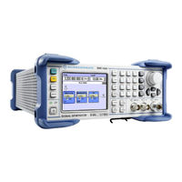
Rohde & Schwarz SMC100A Operating Manual (413 pages)
Signal Generator
Brand: Rohde & Schwarz
|
Category: Portable Generator
|
Size: 5 MB
Table of Contents
-
Preface28
-
Utility Keys31
-
Display32
-
Setup Keys32
-
Display Keys33
-
Power Fuses46
-
Key Features69
-
Display72
-
Messages73
-
Info Window74
-
Editors84
-
File Manager89
-
Display Update102
-
Selftest103
-
Network Settings106
-
Protection113
-
Security114
-
Save/Recall120
-
Factory Preset120
-
Help121
-
Hardcopy Options123
-
Save/Recall Menu127
-
File Manager130
-
RF Block135
-
RF Output135
-
RF Frequency136
-
Phase140
-
Phase Settings140
-
RF Level143
-
RF Level Dialog144
-
User Correction155
-
RF Measurement163
-
RF Sweep Mode171
-
Overview171
-
RF Level Sweep179
-
Modulation184
-
LF Output194
-
LF Output Dialog195
-
Pulse Generator201
-
VISA Libraries206
-
Messages206
-
LAN Interface207
-
Hislip Protocol209
-
Protocol209
-
USB Interface210
-
Serial Interface211
-
Examples215
-
Numeric Suffixes229
-
SCPI Parameters230
-
Numeric Values230
-
Text Parameters232
-
Block Data232
-
Service Request244
Advertisement
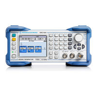
Rohde & Schwarz SMC100A Operating Manual (413 pages)
Signal Generator
Brand: Rohde & Schwarz
|
Category: Portable Generator
|
Size: 5 MB
Table of Contents
-
-
1 Preface
28 -
-
Utility Keys31
-
Display32
-
Setup Keys32
-
Display Keys33
-
-
Power Fuses46
-
-
Key Features69
-
Display72
-
Messages73
-
-
Info Window74
-
-
-
Editors84
-
File Manager89
-
Display Update102
-
Selftest103
-
-
-
Network Settings106
-
Protection113
-
Security114
-
Factory Preset120
-
Save/Recall120
-
Help121
-
Hardcopy Options123
-
Save/Recall Menu127
-
File Manager130
-
RF Block135
-
RF Output135
-
RF Frequency136
-
Phase140
-
Phase Settings140
-
RF Level143
-
RF Level Dialog144
-
User Correction155
-
-
RF Measurement163
-
-
-
RF Sweep Mode171
-
-
Overview171
-
RF Level Sweep179
-
Modulation184
-
-
LF Output Dialog195
-
Pulse Generator201
-
-
Messages206
-
VISA Libraries206
-
LAN Interface207
-
Hislip Protocol209
-
Protocol209
-
Numeric Suffixes229
-
-
SCPI Parameters230
-
-
Numeric Values230
-
Block Data232
-
Text Parameters232
-
Service Request244
-
Error Queue245
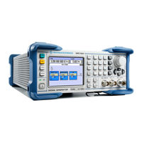
Rohde & Schwarz SMC100A Operating Manual (363 pages)
Signal Generator
Brand: Rohde & Schwarz
|
Category: Portable Generator
|
Size: 4 MB
Table of Contents
-
-
Preface28
-
Utility Keys31
-
Display31
-
Display Keys32
-
Setup Keys32
-
Power Fuses44
-
Key Features68
-
Display71
-
Messages72
-
Info Window73
-
Editors83
-
File Manager88
-
Gui Update100
-
Selftest101
-
Network Settings102
-
Protection108
-
Security108
-
Save/Recall112
-
Factory Preset112
-
Help113
-
Hardcopy Dialog114
-
Hardcopy Options114
-
File Menu118
-
File Manager122
-
RF Output124
-
Frequency Menu126
-
Phase Settings128
-
Phase Menu128
-
RF Level / EMF137
-
RF Level137
-
Alc / Ucor141
-
User Correction143
-
Sweep Mode150
-
Overview150
-
RF Level Sweep158
-
Modulations163
-
Overview163
-
LF Output178
-
LF Output Menu178
-
Pulse Generator178
-
Messages183
-
VISA Libraries183
-
LAN Interface184
-
Protocol185
-
USB Interface186
-
Serial Interface186
-
Examples190
-
SCPI Parameters204
-
Parallel Poll218
-
Serial Poll218
-
Service Request218
-
Error Queue219
-
Advertisement

Rohde & Schwarz SMC100A Manual (352 pages)
Signal Generator
Brand: Rohde & Schwarz
|
Category: Inverter
|
Size: 6 MB
Table of Contents
-
Switching on27
-
Power Fuses29
-
Display52
-
Editors67
-
List Editor67
-
Help System68
-
File Manager72
-
Gui Update84
-
Self Test86
-
Test Point87
-
File Menu107
-
RF Signal - RF112
-
RF Frequency113
-
Frequency - Menu114
-
RF Phase115
-
Phase - Menu115
-
Power Viewer119
-
RF Level125
-
Level - Menu126
-
Rf Emf129
-
EMF - Menu129
-
User Correction132
-
Sweep Mode139
-
Level Sweep Menu147
-
Modulations153
-
Pulse Modulation161
-
LF Output Menu171
-
Getting Started175

Rohde & Schwarz SMC100A Service Manual (159 pages)
Signal Generator
Brand: Rohde & Schwarz
|
Category: Test Equipment
|
Size: 17 MB
Table of Contents
-
Frequency37
-
Harmonics39
-
Nonharmonics40
-
Residual45
-
Level Data49
-
Test Methods60
-
ON/OFF Ratio68
-
Pulse Video71
-
Adjustments76
-
RF Board83
-
LF Generator84
-
Basis Board85
-
Fuses85
-
Controller86
Rohde & Schwarz SMC100A Quick Start Manual (90 pages)
Signal Generator
Brand: Rohde & Schwarz
|
Category: Portable Generator
|
Size: 3 MB
Table of Contents
-
Preface22
-
Utility Keys25
-
Display26
-
Setup Keys26
-
Display Keys27
-
Power Fuses40
-
Key Features63
-
Display66