Table of Contents
Advertisement
Quick Links
CC120x Evaluation Module Kit Quick Start Guide
Opening the Box and Running the Packet Error Rate Test
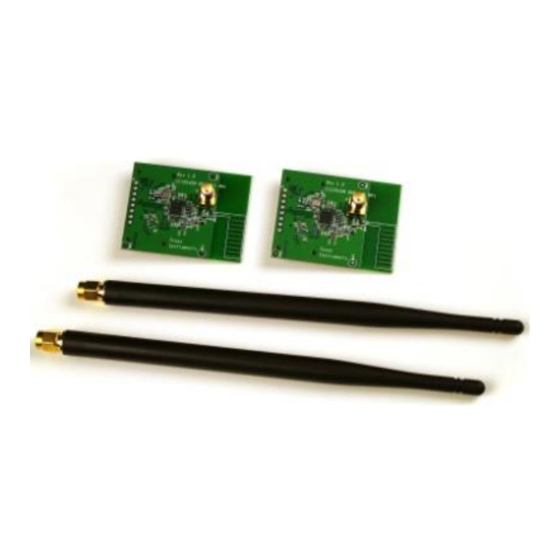
1. Kit Contents
2 x CC1200 or CC1201 Evaluation Modules
2 x Antennas (type depending on frequency)
Antenna types:
868-930 MHz: Pulse W5017, 2 dBi
420-470 MHz: Pulse SPWH24433TI, 0 dBi
4. Select Board Mode
Use the switches S1 and S2 to select the
operating mode of the board. For the sake of this
quick start guide, please select "Enable" and
"UART". This configuration will make it possible
to communicate directly with the MSP430 over a
virtual COM port on the PC.
7. Welcome Screen
Turn on power with the Main Power switch. You
should now see the Texas Instruments logo and
a short description of the buttons on the LCD.
Pushing any of the five buttons on the board will
take you to the main menu.
NB! If you don't see anything on the screen
make sure the mode switches are in the
correct positions (see step 4 above).
2. How to use the Modules
The EMK is an add-on kit to supplement the
CC1200DK with evaluation boards supporting
additional frequency bands. This document
covers the CC1200EMK and CC1201EMK.
The CC120xEM boards can be plugged into
several
development
boards
Instruments. Most notably, you can use the
SmartRF Transceiver EB, which is included in
the CC1200DK. This board lets you run a packet
error rate (PER) test, control the device from
SmartRF™ Studio and it can be used as a
development platform.
It is also possible to connect the EM to other TI
development
boards
with
the
connectors or to the basic "SoC Battery Board".
The latter can be used as a carrier board for the
EM to simplify the connection to other boards
with a microcontroller. See:
http://www.ti.com/tool/soc-bb
This guide will show how to use the modules
together with SmartRF Transceiver EB (TrxEB).
5. Power Options
There are several ways of applying power to the
TrxEB.
2 x 1.5V AA Non-Rechargeable Alkaline
Batteries
USB (5V through USB plug)
External Power Supply (requirements below)
MSP430 Debugger
When the power source is batteries or USB, the
voltage regulators on the TrxEB will set the on-
board supply voltage to 3.3VDC.
i
External Power Supply
Requirements:
Nom Voltage: 3.3VDC
Max Current: 800 mA
Efficiency Level V
Warning! To minimize risk of personal injury or
property
damage,
never
use
batteries to power the board.
8. Packet Error Rate Test
Select the PER (Packet Error Rate) test by
highlighting the selection using the up/down
buttons. Confirm your selection by pressing
Enter (right button).
Web sites:
www.ti.com/lprf
E2E Forum:
www.ti.com/lprf-forum
3. Plug the EM into the TrxEB
from
Texas
appropriate
Insert a CC120xEM board into the TrxEB as
shown above. Connect the antenna to the SMA
connector on the EM.
Caution!
sensitive components. Handle with care
to prevent permanent damage.
6. Select Power Source
Depending on the power source, make sure you
connect jumpers to the appropriate pins on the
"Power Source" header. For instance, if you use
batteries, use a jumper to short-circuit pin 1 and
2 on the header. The last jumper in the row (pin
9-10) should always be mounted, unless the
MSP430 FET is used as the power source.
Note that there should only be one active
power source at any one time. Do not leave
rechargeable
the board powered when unattended.
9. Select Test Mode
The PER test can be run is several modes. Easy
Mode sets up a one-way test and uses default
settings. This test is convenient for practical
range testing.
The other test modes are described in the
"TrxEB RF PER Test Software Example User's
Guide", available on the kit web page.
To proceed, highlight "Easy Mode" and press
Enter (right button).
Make sure to subscribe to the Low-Power RF
Newsletter to receive information about updates to
documentation, new product releases, and more.
Sign up on the TI web pages.
SWRU337A
August 2015
The
kit
contains
ESD
Advertisement
Table of Contents

Related Manuals for Texas Instruments CC120 Series


Summary of Contents for Texas Instruments CC120 Series
- Page 1 Select the PER (Packet Error Rate) test by The PER test can be run is several modes. Easy should now see the Texas Instruments logo and highlighting the selection using the up/down Mode sets up a one-way test and uses default a short description of the buttons on the LCD.
- Page 2 10. Select Frequency 11. Select Mode 12. Establish Link One of the boards must operate as the slave The slave node will now wait for a configuration (transmitter) and the other as master (receiver). package from the Master. The configuration Select Slave on one board…...
- Page 3 STANDARD TERMS AND CONDITIONS FOR EVALUATION MODULES Delivery: TI delivers TI evaluation boards, kits, or modules, including any accompanying demonstration software, components, or documentation (collectively, an “EVM” or “EVMs”) to the User (“User”) in accordance with the terms and conditions set forth herein. Acceptance of the EVM is expressly subject to the following terms and conditions.
- Page 4 FCC Interference Statement for Class B EVM devices NOTE: This equipment has been tested and found to comply with the limits for a Class B digital device, pursuant to part 15 of the FCC Rules. These limits are designed to provide reasonable protection against harmful interference in a residential installation.
- Page 5 【無線電波を送信する製品の開発キットをお使いになる際の注意事項】 開発キットの中には技術基準適合証明を受けて いないものがあります。 技術適合証明を受けていないもののご使用に際しては、電波法遵守のため、以下のいずれかの 措置を取っていただく必要がありますのでご注意ください。 1. 電波法施行規則第6条第1項第1号に基づく平成18年3月28日総務省告示第173号で定められた電波暗室等の試験設備でご使用 いただく。 2. 実験局の免許を取得後ご使用いただく。 3. 技術基準適合証明を取得後ご使用いただく。 なお、本製品は、上記の「ご使用にあたっての注意」を譲渡先、移転先に通知しない限り、譲渡、移転できないものとします。 上記を遵守頂けない場合は、電波法の罰則が適用される可能性があることをご留意ください。 日本テキサス・イ ンスツルメンツ株式会社 東京都新宿区西新宿6丁目24番1号 西新宿三井ビル 3.3.3 Notice for EVMs for Power Line Communication: Please see http://www.tij.co.jp/lsds/ti_ja/general/eStore/notice_02.page 電力線搬送波通信についての開発キットをお使いになる際の注意事項については、次のところをご覧くださ い。http://www.tij.co.jp/lsds/ti_ja/general/eStore/notice_02.page SPACER EVM Use Restrictions and Warnings: 4.1 EVMS ARE NOT FOR USE IN FUNCTIONAL SAFETY AND/OR SAFETY CRITICAL EVALUATIONS, INCLUDING BUT NOT LIMITED TO EVALUATIONS OF LIFE SUPPORT APPLICATIONS.
- Page 6 Notwithstanding the foregoing, any judgment may be enforced in any United States or foreign court, and TI may seek injunctive relief in any United States or foreign court. Mailing Address: Texas Instruments, Post Office Box 655303, Dallas, Texas 75265 Copyright © 2015, Texas Instruments Incorporated...
- Page 7 IMPORTANT NOTICE Texas Instruments Incorporated and its subsidiaries (TI) reserve the right to make corrections, enhancements, improvements and other changes to its semiconductor products and services per JESD46, latest issue, and to discontinue any product or service per JESD48, latest issue.
Need help?
Do you have a question about the CC120 Series and is the answer not in the manual?
Questions and answers